Creating Conceptual mass in REVIT and Creation of Sinusoidal curve and a Parametric stadium using Dynamo
Q1)
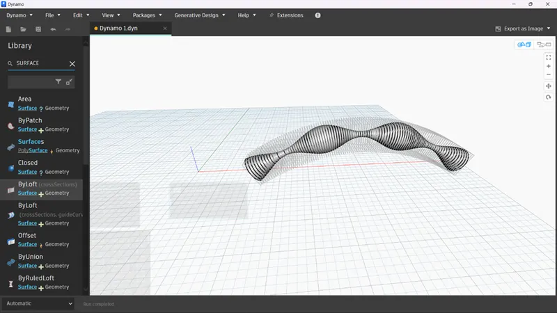
1) Using Dynamo create a set of sinusoidal points and create a curve and create a surface out of the curve.
AIM :
1) Using Dynamo create a set of sinusoidal points and create a curve and create a surface out of the curve.
PROCEDURE:
- open Revit, go to manage tab and select dynamo,
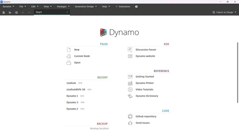
- we get an interface as shown below
- after opening dynamo, search points in the search option and bring them on the screen
- then search code blocks and bring them on the screen and enter values.
- now search sliders in the search option and bring them on the screen, set their values as 0 to 50and 50 to 100.
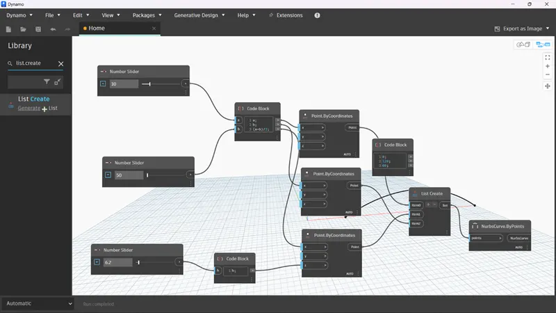
- give the inputs of both the sliders to the variables a and b in the code block, and the output of which are connected to x of all the three points by co ordinates.
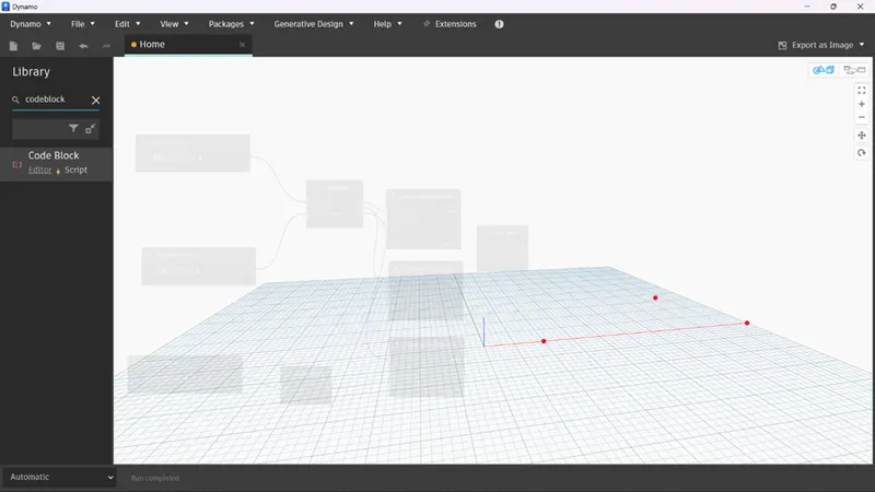
- introduce another code block and name it as points height and give the variable as h, take another number slider ,connect its output to the input of height and the output of height is connected to z co ordinate of middle point by co ordinates.
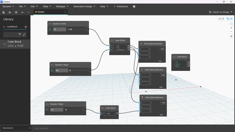
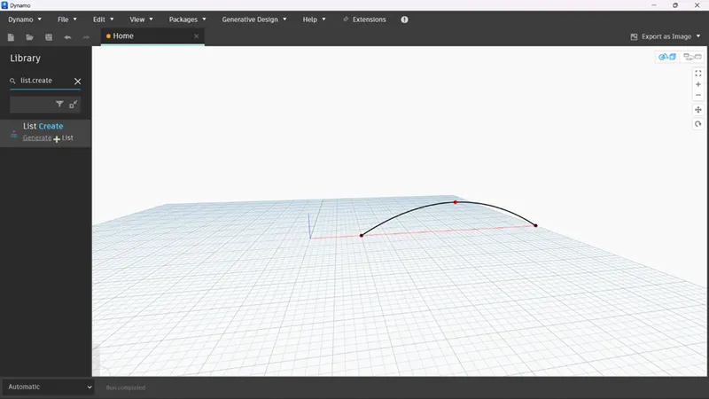
- if we make an increase in the number slider we can see the inclined point system in the form of curve.
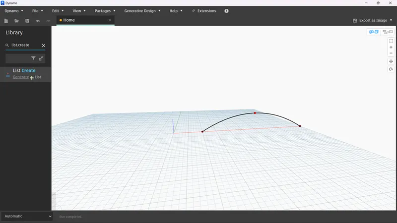
- to make it to curve introduce nurbs by points and list on to the interface, connect the output of points by co ordinate to each input of list.create.
- output of list is connected to the input of nurbscurve ,we get a curve as shown below
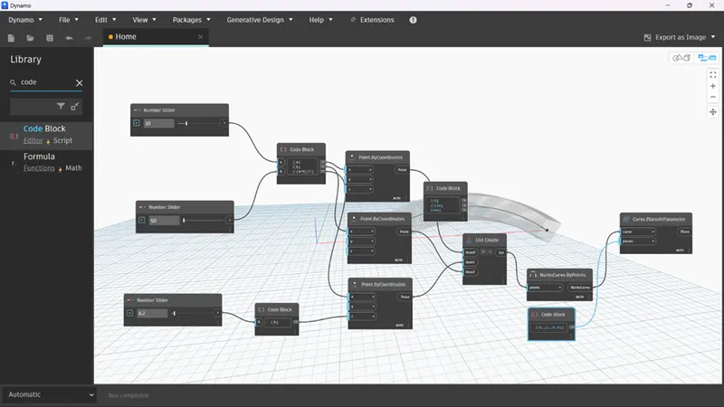
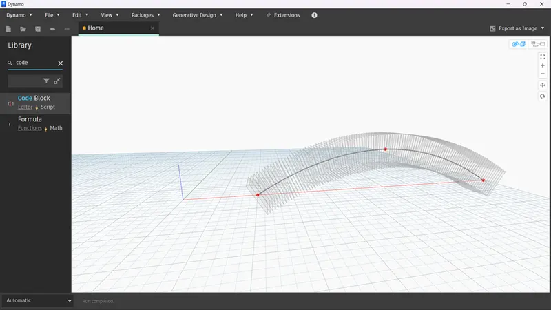
- now introduce plane at parameter onto the interface and connect the output of nurbs to the input of curve( plane at parameter) in order to give input to the second input of (plane at parameter) take another code block and enter its values.
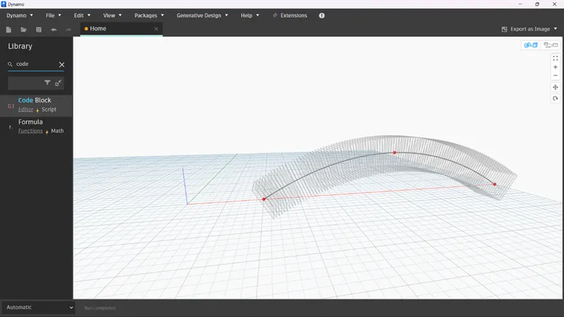
- we get a surface as shown below
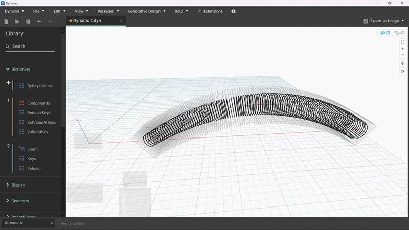
- now introduce circle onto the screen ,connect the output of plane parameter to the input of circle.
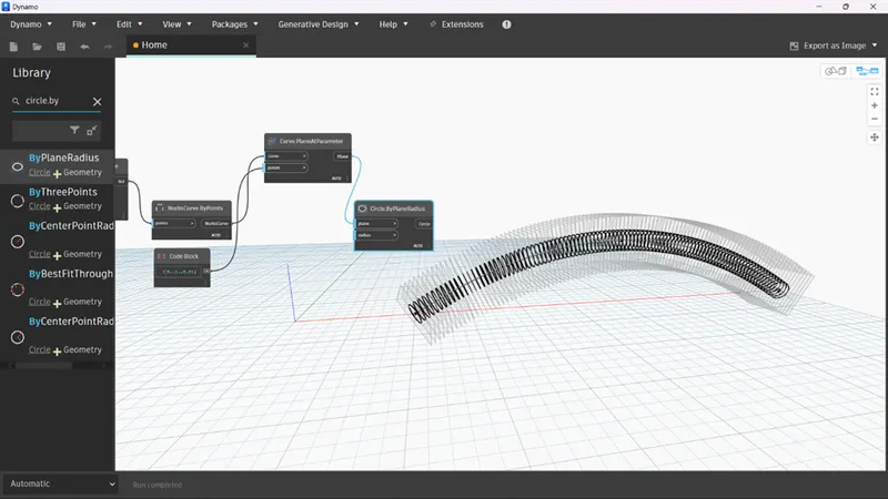
- in order to give radius create a code block and name it as phase+math.sin(amplitude*ang); give the inputs to the amplitude and angle using code block.
- connect its output to the radius of circle
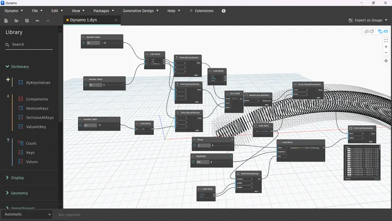
- Add a number slider with the name amplitude and another slider with the name phase.
- Connect it to the formula codeblock.
- Add math math.remaprange and set the new min and new max with the help of a code block.
- Then connect the remap range to angle.
- Now we get an output like:
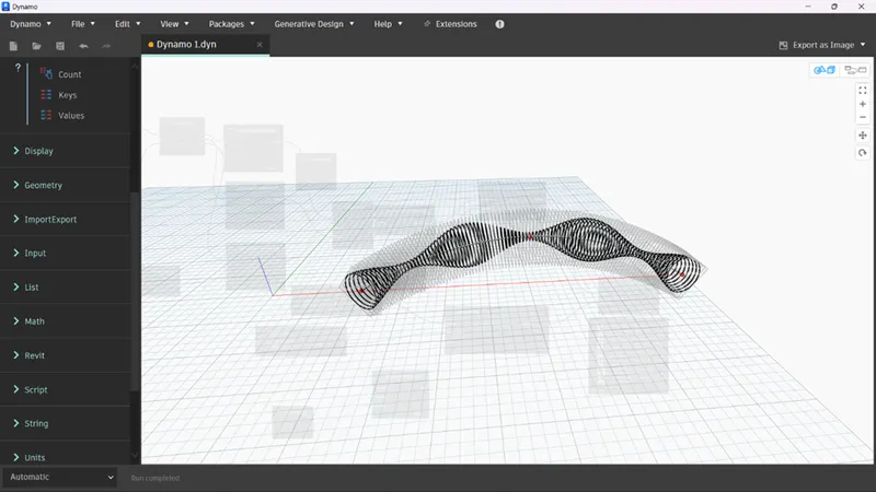
- We can change the phase and amplitude slider to change the parametric structure’s appearance.
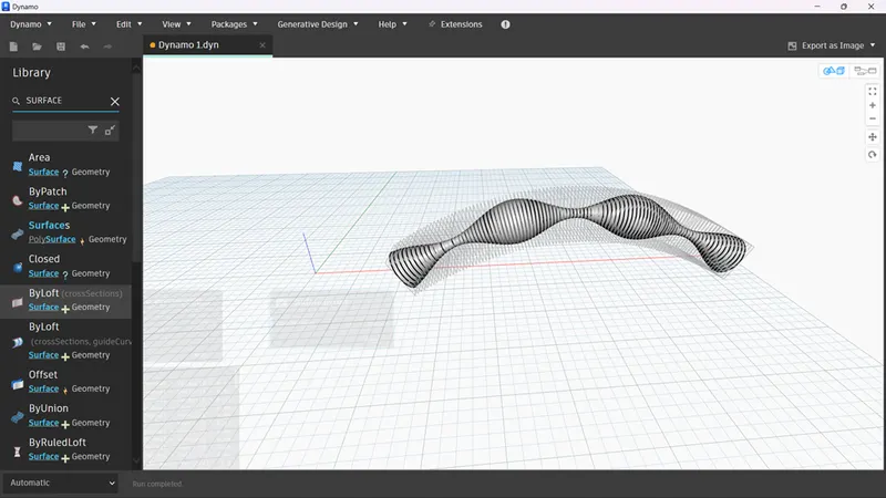
- Then search surface by loft and connect the circle by plane with it to form a surface.
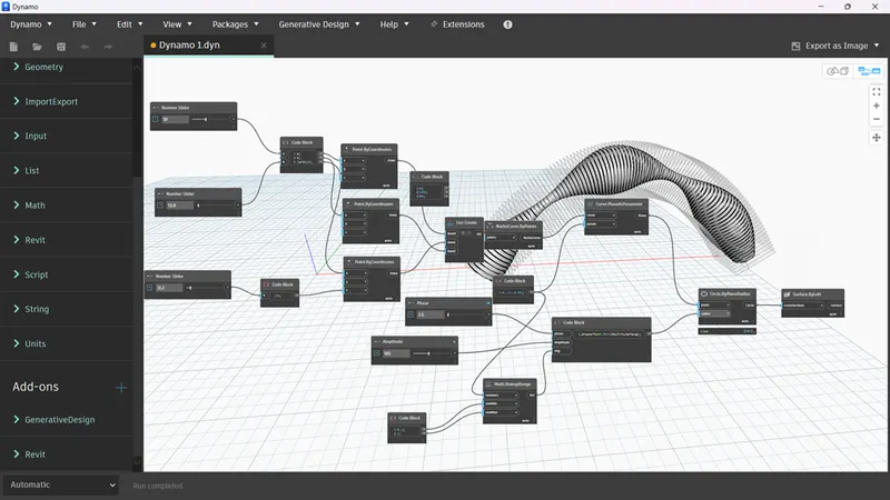
Result:
- A set of sinusoidal points has been created and using them a sinusoidal curve has been created a surface has been given to the curve.
Q2)
AIM :
Create a conceptual layout of floor plan in dynamo . Using the tools available in dynamo link the lines to appropriate model elements in Revit by choosing the wall types and wall parameters. Make use of the sliders to slide through the height of the wall and length of the wall.
PROCEDURE :
- open dynamo and search points from the search option and bring them on the screen.
- give different names to each point as shown in figure.
- now bring number slider on the screen and name them as x and y,set their limits as 10 to 100.
- connect the output of x and y to control point 1 followed by 2 and 3 as shown in figure.
- now introduce line by start point end point onto the screen.
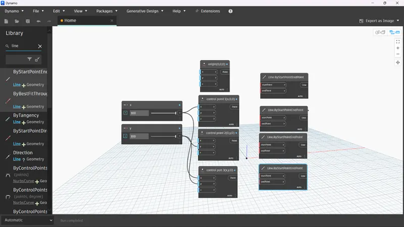
- connect the output of points to the input of lines by start point end point i.e origin to start point end point to control point 1. in this way connect all the points forming a layout as shown in figure.
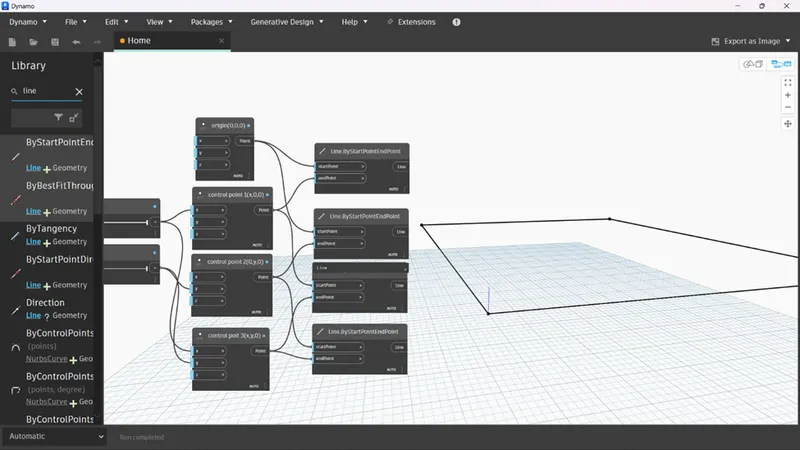
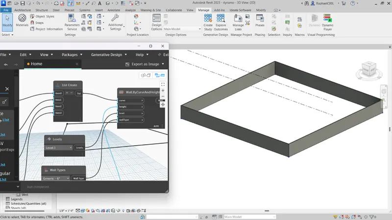
- now introduce wall by curve onto the screen and its required inputs such as levels,height,wall type and curve.
- set the wall type as generic 6'', followed by height as 10 to 40 using number slider.
- now introduce the list option and connect the output of lines to the input of list,
- then connect its output to the curve.
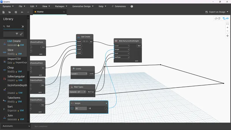
- go back to the revit screen ,change the view to 3d, you can alter the height of the layout using the height option(number slider),can increase or decrease it.
Q3)
AIM :
Create an array of model elements in Revit. Use dynamo to vary the properties of model elements by using the slider or code block.
PROCEDURE:
- open revit and draw a rectangular column ,copy the same and place it beside the previous column.
- now copy the group of two columns and place them above the previous group forming a group of 4 columns.
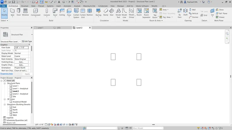
- now go to manage tab and open dynamo.
- search select model elements, set rotation and bring them on the screen.
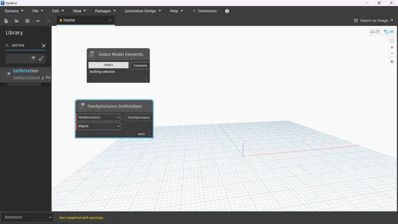
- now click the select option and select all the four columns, you get a value.
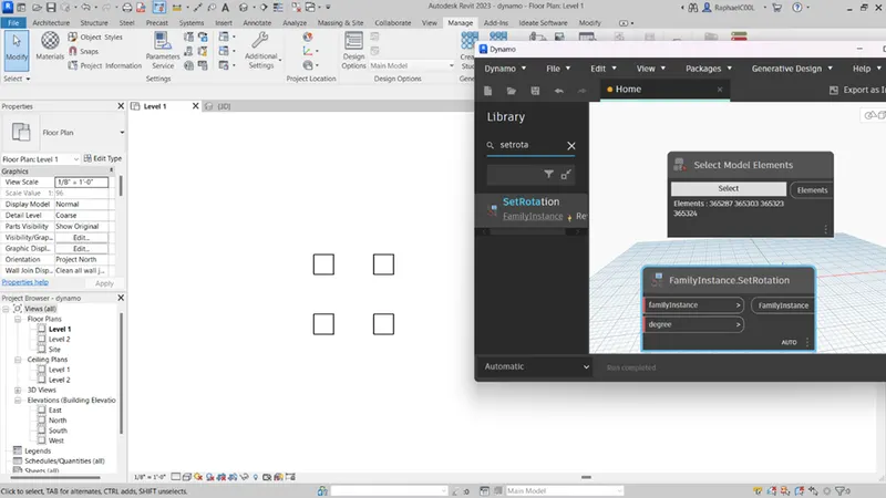
- now insert code block and enter the angle,connect its output to the degree.
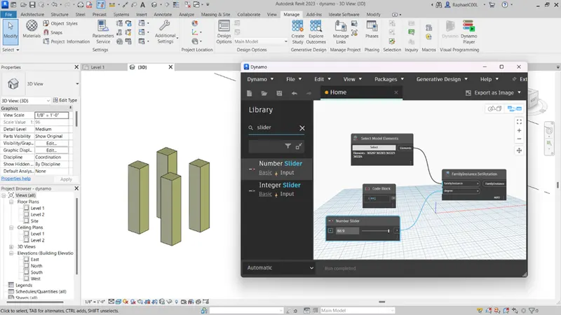
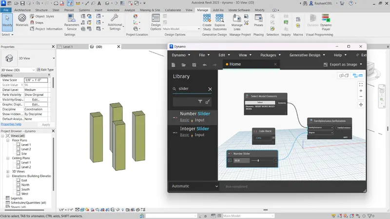
- we can see all the four columns have been rotated at an angle of 60.
- now insert number slider and connect it to the degree.
- as we increase the cursor in number slider we can see the changes in revit screen in 3d.
Q4)
AIM :
Create a conceptual mass in Revit and develop a parametric column by dividing the surfaces and apply the concepts similar to used in parametric walkway modelling. Use triangular bent or square shaped panels to add finish to the parametric column.
PROCEDURE:
- open revit ,go to the file option and select families.
- open conceptual mass from the family.
- we get an interface as shown below.
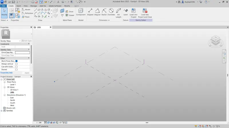
- change the view to north view and increase the level to 10'.
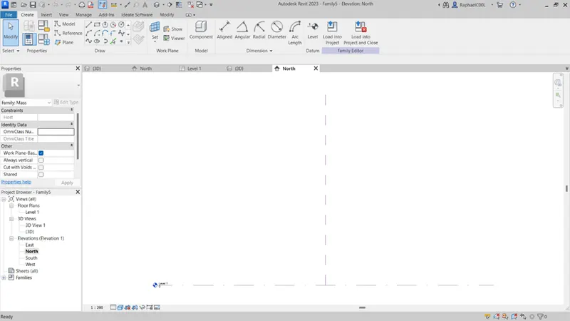
- go to the floor plan view, we get an interface as shown.
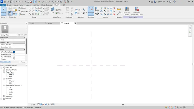
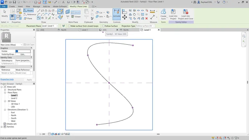
- select the spline option and draw as shown below.
- change the view to 3d.
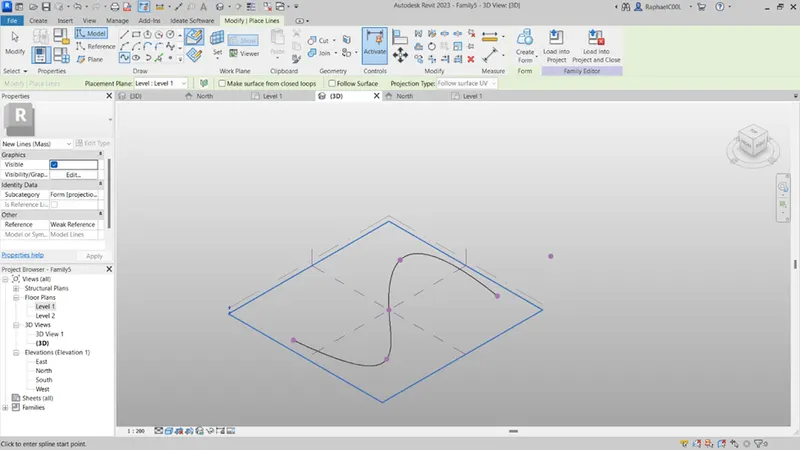
- Set a plane at a control point and draw a square.
- And repeat that step at all the control points.
- Then select the spline and the squares and click on create form to create a 3d model.
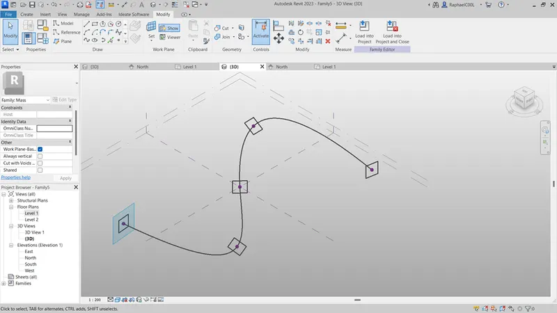
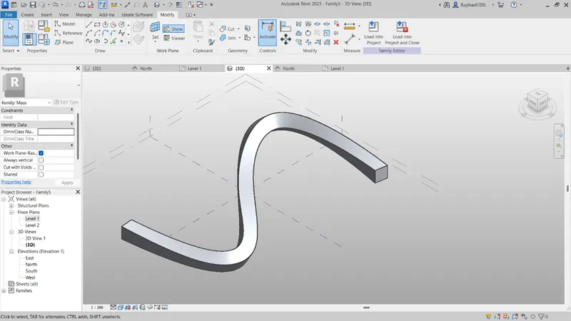
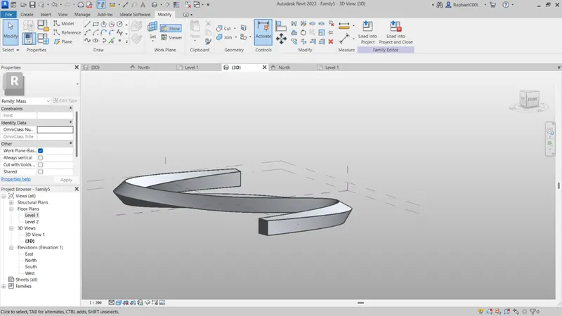
- Now select the whole model and select only the form with the help of filter.
- Click on divide surface
- It will divide the whole surface.
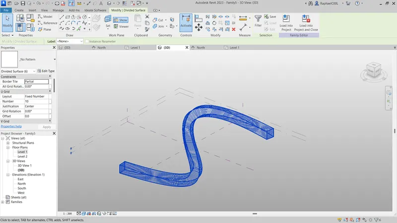
- Then select the model and select only form through filter.
- Then change its border to desired shape like triangle (bent)
- If the faces warp then you can correct them by increasing the number of grids from the properties browser.
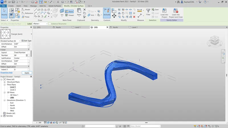
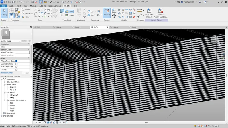
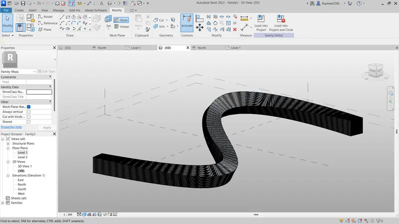
- now go the file option select families and select curtain wall pattern based.
- Change the pattern to which you have applied to the model, in my case triangle (bent)
- Add a reference point at the mid of any one side.
- Add a plane to that point and draw a circle of radius 2”.
- Select the circle and the triangle and click on create form.
- Then click on load into project and close.
- Then apply the created family to the model by select on face at a time.
- The final model will appear as shown below:
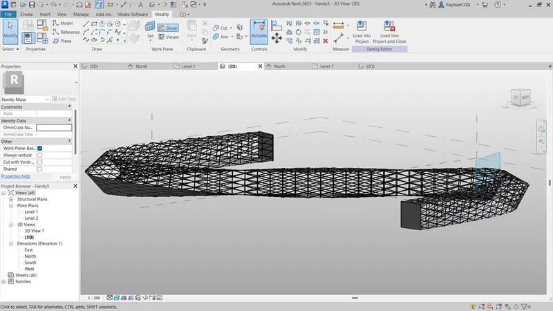
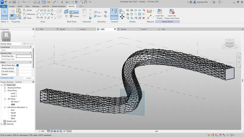
Result:
- A conceptual mass has been created and a parametric walkway has been developed using triangular bent panels.
Q5)
AIM :
Use Dynamo to work on developing a Parametric Stadium. List your parameters and use the visual programming approach to complete the modelling, You can use the concepts discussed in parametric high rise tower in class for reference.
PROCEDURE:
- First open Revit and draw a base of 120m x 90m.
- Open dynamo and search select model elements and select the base from Revit.
- Then add sliders and point by coordinate and connect the three sliders with x, y, and z to control the position of the centre point.
- Then add a point, then a circle.bycentrepointradius for the base circle.
- Add a number slider and name it ground floor radius.
- Then connect it to the circle block.
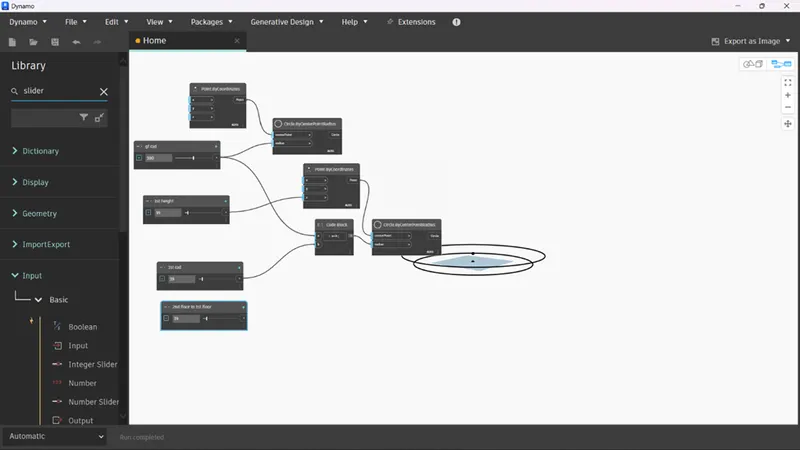
- Create another point and circle blocks and do the same procedure and name the slider as 1st floor HEIGHT, this will create a circle above the ground floor base circle at the height set in the slider
- Insert a code block, and write a+b; in it to connect the ground floor and first floor radius sliders so that both the radii change simultaneously.
- Connect the code block to the circle.bycenterpointradius block which will create a circle for first floor.
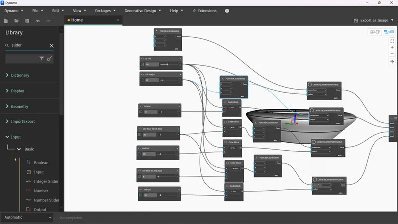
- The resulting figure will be like as shown below:
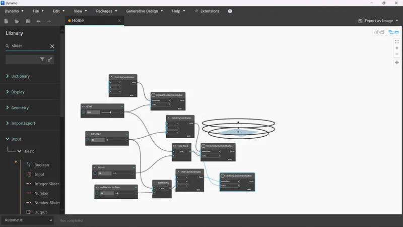
- Repeat the same procedure that we did for 1st floor again and name the sliders for the 2nd
- This will create the base for 2nd floor will be appear as follows:
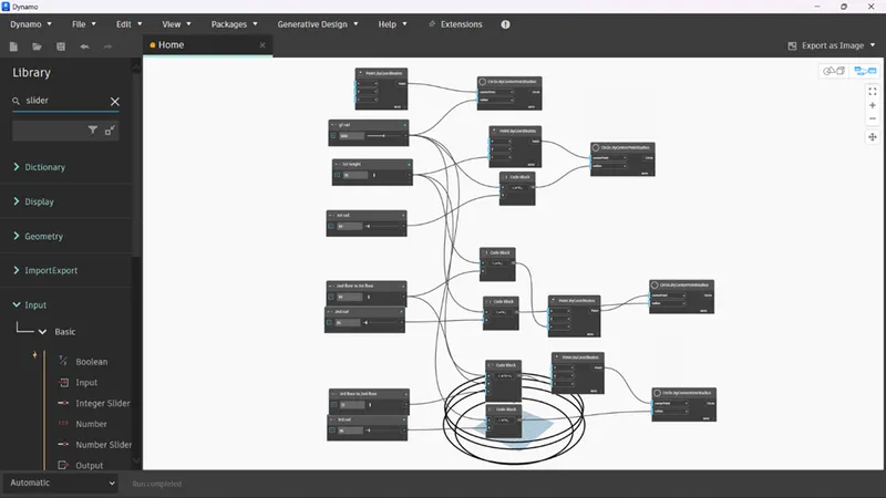
- Similarly the 3rd floor will be created. And the whole chart will appear something like this:
- Now search and insert create list.
- Then add 3 items to the list.
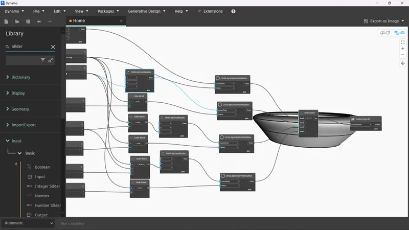
- Then connect all the four circle blocks to the list block.
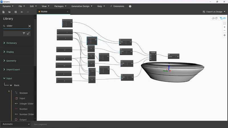
- Search and insert surface by loft and connect the list block to it to create a surface connecting all the circles which will appear as shown below:
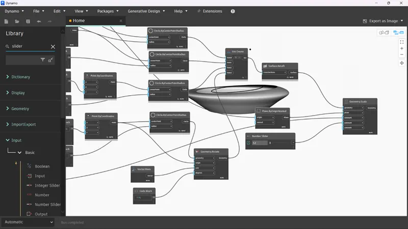
- Search and insert geometry scale, plane by origin normal.
- Connect the surface block to the geometry.
- Connect the origin coordinate to the origin of the plane block.
- And the connect the plane to the geometry block.
- Search and insert two sliders and connect them to xamount and yamount to change the size of the created plane along x and y axis.
- Doing this creates a plane which will give a smooth finish to the model.
- Search and insert geometry rotate.
- Connect the top circle i.e., the 3rd floor circle to the rotate block.
- Connect the circle’s coordinate block to the rotate block.
- Search and insert y-axis vector and connect it to the rotate block.
- Search and insert a slider to control the degree of rotation and connect it to the rotate block.
- These whole steps will result it controlling the rotation of the 3rd
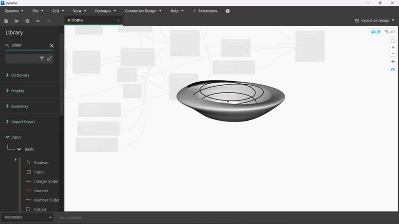
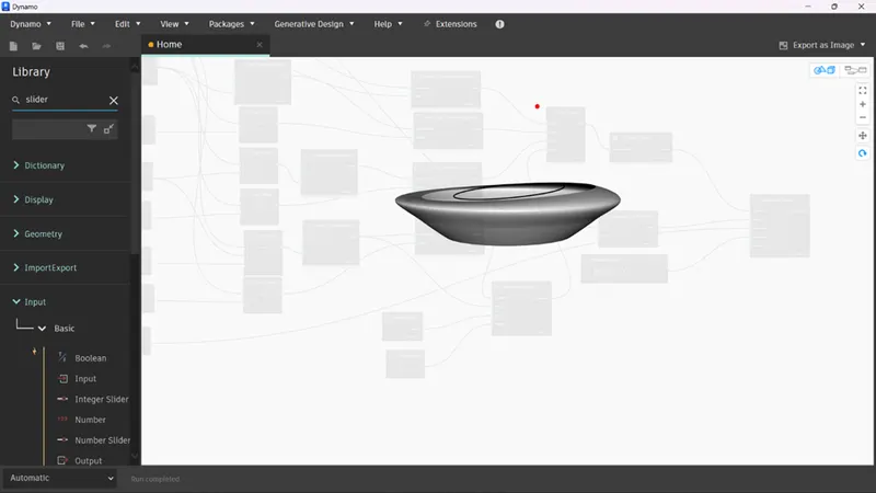
- With this our parametric stadium is complete.
Result:
- The parametric stadium has been created using the visual programming approach.