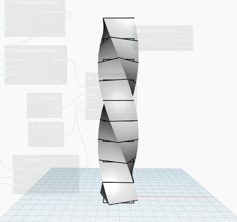
Creating Conceptual mass in REVIT and Creation of Sinusoidal curve and a Parametric stadium using Dynamo
Creating Conceptual mass in REVIT and Creation of Sinusoidal curve and a Parametric stadium using Dynamo
QUESTION:-1
Using Dynamo, create a set of sinusoidal points, a curve, and a surface out of the curve.
ANSWER
AIM:To create a set of Sinusoidal points, a curve, and a surface out of the curve using dynamo
INTRODUCTION:
- Dynamo is a visual programming tool that works with Revit. Dynamo extends the power of Revit by providing access to the Revit API (Application Programming Interface) in a more accessible manner. Rather than typing code, with Dynamo you create programs by manipulating graphic elements called “nodes”. It’s an approach to programming better suited for visually oriented types, like architects, designers, and engineers.
- In Dynamo, each node performs a specific task. Nodes have inputs and outputs. The outputs from one node are connected to inputs on another using “wires”. The program or “graph” flows from node to node through the network of wires. The result is a graphic representation of the steps required to achieve the end design.
NODES USED:
1. Integer slider
2. Range
3. Point by coordinates
4. Math. sin
5. Code block
6. Product
7. NurbsCurve by coordinates
8. List create
9. Surface by loft
PROCEDURE:
STEP:- 1
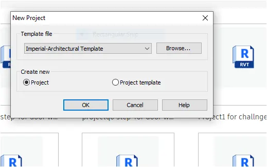
1. Open Revit software and select the New template file
2. Select the Template file as Imperial-Architectural and press OK
STEP :-2
1. Go to the manage tab and select the dynamo option
2. It will open the dynamo software in a new window

STEP :-3
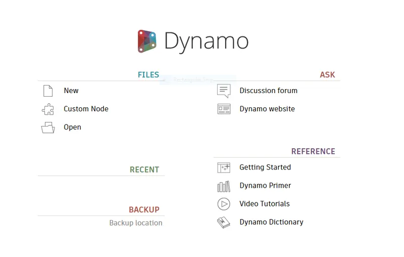
1. After opening the dynamo software, click on New file under the File tab
STEP-4
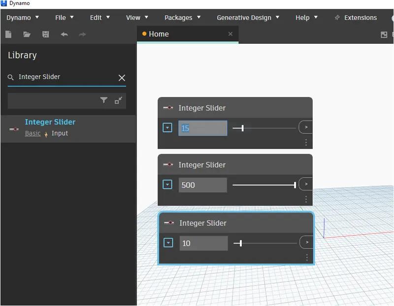
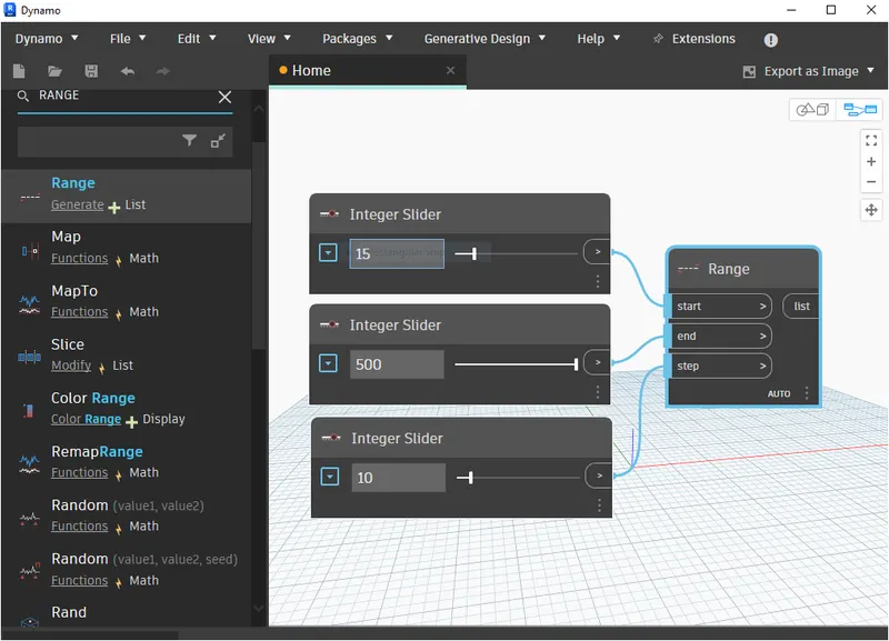
1. Select the integer slider by searching the integer slider in the library search box
2. Select three sliders and give the input values as 15 for the start point, 500 for the endpoint, and 10 for step
STEP 5:
1. In the library search box, type range and select the range node
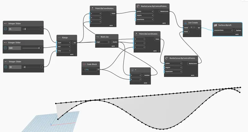
2. Connect all the sliders to the range node appropriately as shown in the figure below
STEP:-6
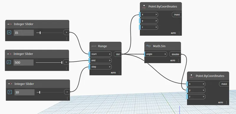
1. Then Search for point by coordinates and Select two points by coordinates node
2. Then Connect the range list wire to X Co-ordinates as shown in the figure below
2. Similarly search for math. sin node and connect the wire from range to math. sin and math. sin to Y port as shown in the figure below
STEP:-7
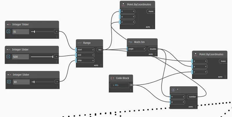
1. Search for code block and give the code as 50;
2. Now we have to insert the product node, search for a product in the library and select the product node
3. Connect the wires from code block to Z coordinates and code block to Y product
4. Then connect the wires from Z coordinates to number product and math. sin to X product as shown in the figure below
STEP:- 8
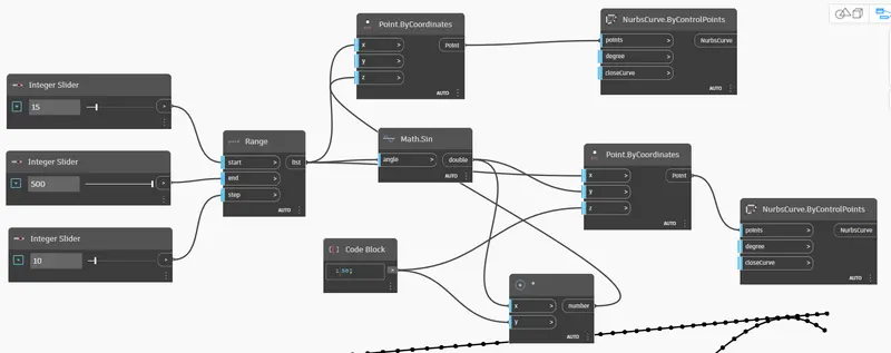
1. In the library search box, search for NurbsCurve by control points
2. Select two NurbsCurve by control points nodes
3. Then connect the two wires from the point by coordinates to NurbsCurve by control points respectively
STEP:-10
1. Select the List to create a node option from the library search
2. We have to connect two NurbsCurve into the list, so expand the items into two items (i.e., item 0 and item 1)
3. Then connect the wires from NurbsCurve to Item 0 and item 1 respectively as shown in the figure below
4. After creating the curves, now we have to make a surface out of the curve
5. In the library search box, search for surface by loft node and select it
6. Then connect the wires from the list node that we created to Surface by loft node
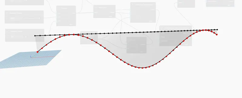
7. Hence the Surface has been created out of the curve
RESULT:
- The Sinusoidal points, curve, and surface have been created successfully using dynamo
QUESTION:-2
Create a conceptual layout of the floor plan in dynamo. Using the tools available in dynamo link the lines to appropriate model elements in Revit by choosing the wall types and wall parameters. Make use of the sliders to slide through the height of the wall and the length of the wall.
ANSWER
AIM:To create a conceptual layout of the floor plan in dynamo using various tools and parameters
INTRODUCTION:
- The workspace is the place where designers develop visual programs but it is also the place where any elaborate geometry is previewed.
- The conceptual mass of a building contains different types of parameters like level, floor area, and floor perimeter, and the architect can generate early quantities of takeoff from the mass. In Bim modeling services the conceptual mass of a building can be exported to any other format for performing early energy analysis.
NODES USED:
1. Integer slider
2. Point by coordinates
3. Line by start point endpoint
4. List create
5. Code block
6. Levels
7. Wall types
8. Floor types
9. Wall by curve and height
10. Floor by outline type and level
PROCEDURE:
STEP:-1
1. Open Revit software and select the New template file
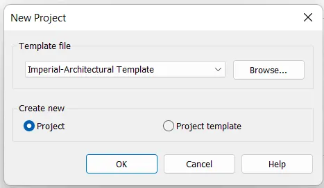
2. Select the Template file as Imperial-Architectural and press OK
STEP:-2
1. Go to the manage tab and select the dynamo option
2. It will open the dynamo software in a new window
STEP:-3
1. After opening the dynamo software, click on New file under the File tab
STEP:-4
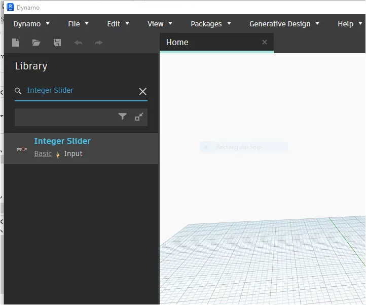
1. Select the integer slider by searching the integer slider in the library search box
2. Select two sliders and give the input values as 150 for the length of the wall and 150 for the width of the wall
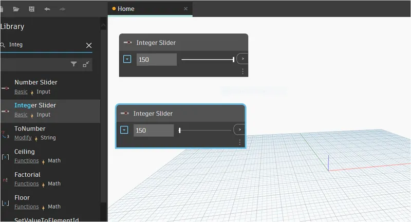
STEP:-5
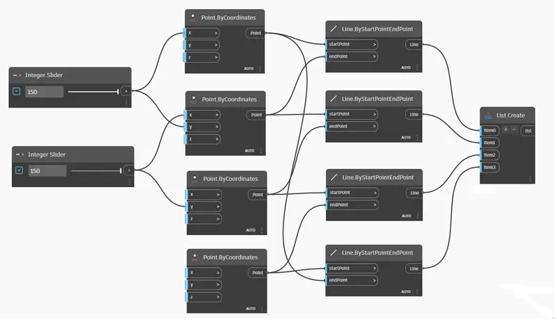
1. In the search box, type point by coordinates node and select four points by Coordinates nodes
2. Then connect the wires from the first integer slider to the first node X coordinates and second node Y coordinates
3. Similarly connect the wires from the second integer slider to second node X coordinates and Third node Y coordinates as shown in the figure below
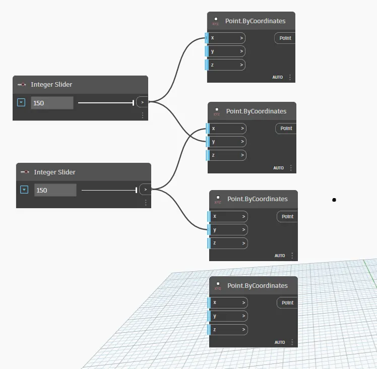
STEP:-6
1. In the search box, type line by start point end point and select four lines by start point end point nodes
2. Connect all the wires from the point by coordinates to the start point of the line by the start point end point node As shown in the figure below
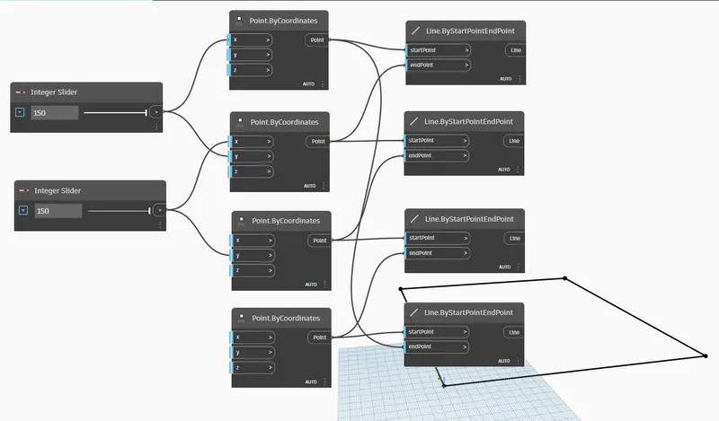
STEP:-7
1. Then the rectangle is created by the Coordinate points as shown in the figure below
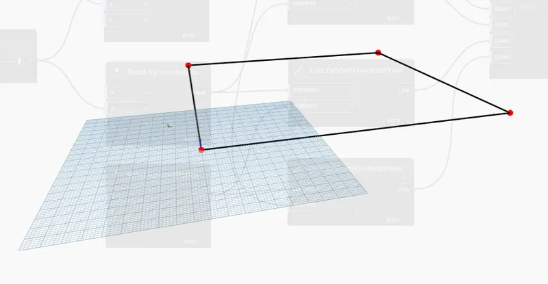
STEP:-8
1. Select the list to create a node by typing list create on the search box
2. Now we have to connect all the four lines by start point end point nodes to list
3. Hence expand the list of items from item 0 to item 3
4. Then connect all the wires from the line by start point end point nodes to list created items respectively
STEP:-9
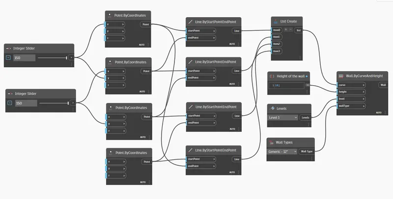
1. Now we have to give the parameters such as the height of the wall, levels, and wall types
2. In the library search box, type code block, levels, and wall types and select all the nodes
3. Next we have to give the code as 10 for the height of the wall
4. Similarly select the level type as level 1 and wall type as generic 12"
5. In the search box, type wall by curve and height and select the node
6. Then connect the wires from the list to curve, height of the wall to height, levels to level, and wall type to wall type as shown in the figure below
STEP:-10
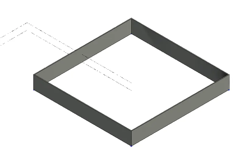
1. To cross-check this, open the Revit software and see the result
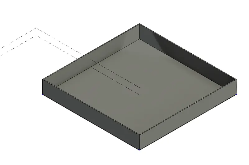
2. The wall has been created with all the parameters that we have given in the dynamo
STEP:-11
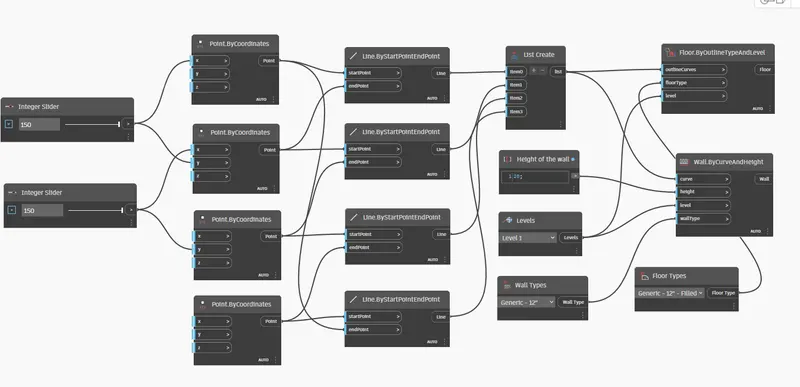
1. Then we have to provide the flooring for the wall layout
2. In the library search box, type Floor types and select the node
3. Select the floor type as generic 12" filled
4. Then again search the floor by outline type and level node and select it
5. Then connect the wires from the list to outline curves, floor type to floor type, and levels to level as shown in the figure below
RESULT:
- The conceptual layout of the floor plan has been created successfully using various tools in dynamo
QUESTION:-3
Create an array of model elements in Revit. Use dynamo to vary the properties of model elements by using the slider or code block
ANSWER
AIM:To create an array of model elements in Revit. Use dynamo to vary the properties of model elements by using the slider or code block
INTRODUCTION:
- The visual programming tool of Dynamo extends the power of Revit and provides access to the Revit Application Programming Interface (API) in a more accessible manner. Using Dynamo, one can create programs by manipulating graphic elements called “nodes” rather than typing code. Moreover, this programming approach will be better suited for visually oriented types such as engineers, designers, and architects. Apart from that, a visual programming environment can assist designers to automate tasks as well as explore parametric conceptual designs.
- By integrating Dynamo for Revit workflow concepts into the execution of a project, data entry and repetitive work can be streamlined to improve efficiency and productivity across all disciplines, and through various phases of the project.
NODES USED:
1. Select model elements
2. Integer slider
3. Family instance set rotation
PROCEDURE:
STEP:-1
1. Open Revit software and select the New template file
2. Select the Template file as Imperial-Architectural and press OK
STEP:-2
1. Now we have to load any model element into the template
2. From the architectural tab, select the components tool and click on the load family option
3. Select any model element and load it to the screen
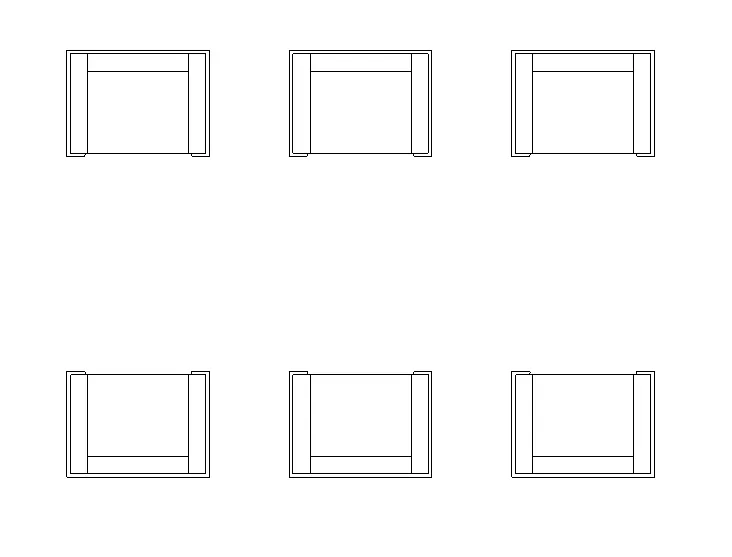
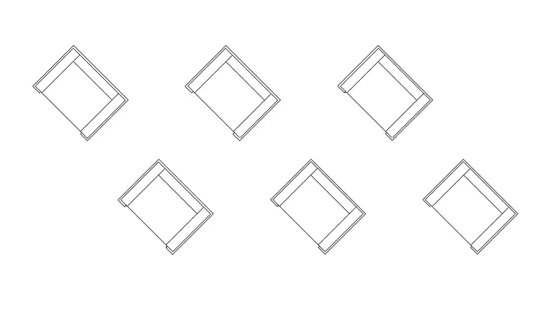
4. Here, we have selected the six sofa chairs as shown in the figure below
STEP:-3
1. Go to the manage tab and select the dynamo option
2. It will open the dynamo software in a new window
STEP:-4
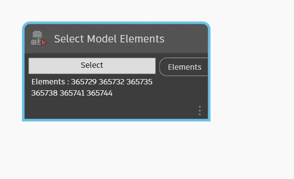
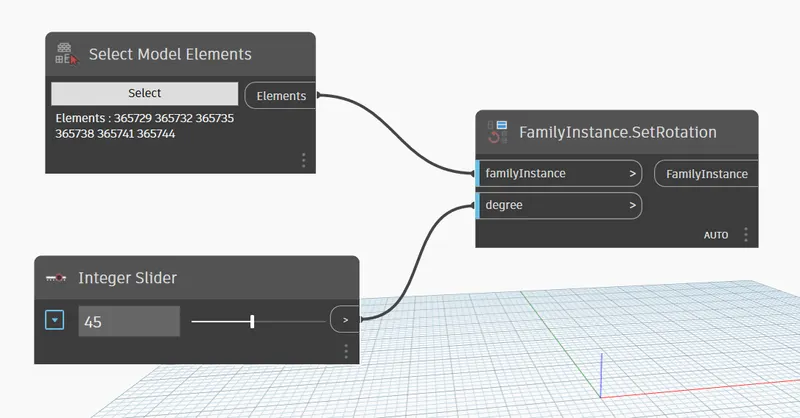
1. In the library search box, type select model elements and select the node
2. Then Click on the select option in the node. Then go to the Revit window and select all the elements
3. It will automatically be selected in the dynamo software as shown in the figure below
STEP:-5
1. In the library search box, type integer slider and select the slider
2. Then give the integer slider value as 45 degrees
3. In the search box, again type family instance set rotation and select that node
4. Then connect the wires from the elements to the family instance and integer slider to a degree as shown in the figure below
5. The model elements in the Revit have changed their rotation
RESULT:
- The array of model elements has been created successfully and their properties are being varied through the blocks created in Dynamo
QUESTION:-4
Create a conceptual mass in Revit and develop a parametric column by dividing the surfaces and applying concepts similar to those used in parametric walkway modeling. Use triangular bent or square-shaped panels to add a finish to the parametric column.
ANSWER
AIM: To create a conceptual mass in Revit and develop a parametric column by dividing the surfaces and applying the triangular bent panels
INTRODUCTION:
- Creating conceptual mass families means that the mass is external to the project. It uses the same tools to create the mass family, which is then saved and loaded into the project.
- Conceptual Mass Modeling Services is an important part of Revit Modeling Services. This 3D mass modeling is generally performed by architects. One of the purposes of mass modeling is to create 3D models of odd-shaped buildings. Using this 3D modeling process, users create a base for any odd-shaped building.
- In Revit Modeling Services, a Conceptual 3D mass modeling process is also performed to conceptualize the conceptual geometry of a building i.e. architects can understand overall building massing indicative of the area, height, volume, location, weight, and orientation.
PROCEDURE:
STEP:-1
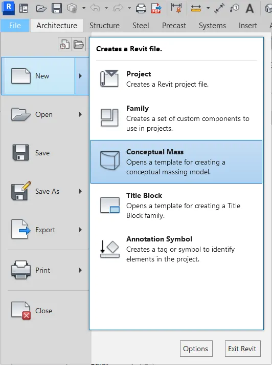
1. Open the Revit software and click on the new Revit file
2. Then select the Revit file as conceptual mass
STEP:-2
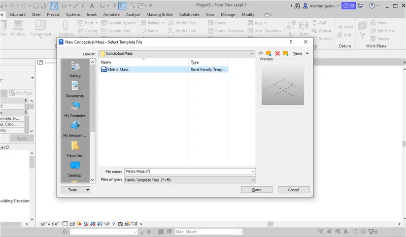
1. After selecting the conceptual mass file, it will open the libraries folder
2. Select the conceptual mass file as a metric mass template and load it
STEP:-3
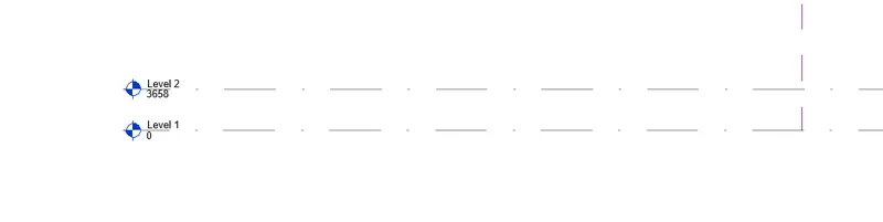
1. Now we have to create two levels at a height of 12'
2. In the modify tab, click on create levels and create another level with an offset of 12' as shown in the figure below
STEP:-4
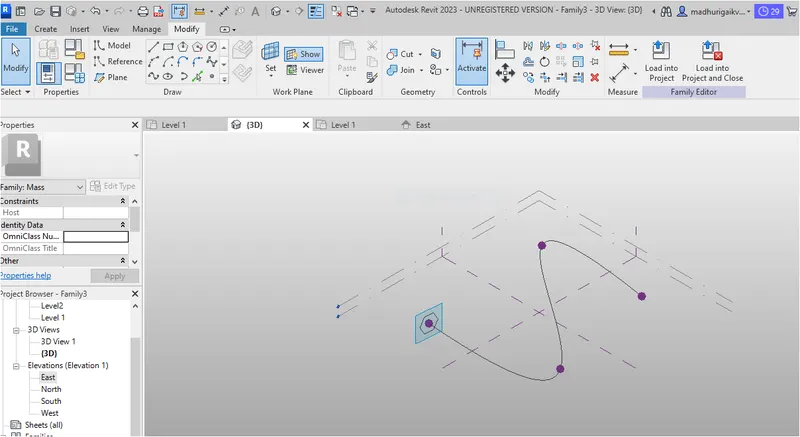
1. Now go to the modify tab and select the model line option
2. Then select the spline tool and draw the walkway curve mentioning four points as shown in the figure below

STEP:-5
1. Create the workplace plane at all the control points
2. Then select the circumscribed polygon and draw it on the control point with a radius of 12'
STEP:-6
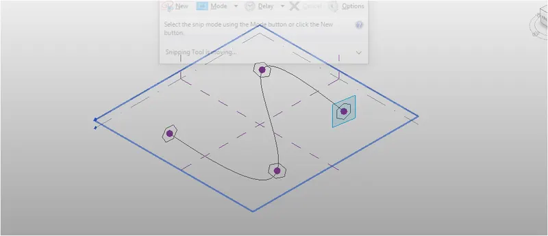
1. The polygon will be created at the control point
2. Similarly draw the circumscribed polygons on all the control points with a radius of 12' as shown in the figure below
STEP:-7
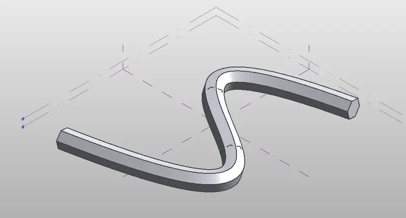
1. Select the curve line and control points and click on create a form under the modify tab
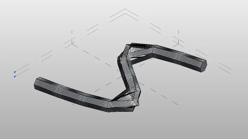
2. It will create the solid curve of the spline as shown in the figure below
STEP:-8
1. Then select all the elements and go to the filter option
2. Select only the form using the filter tool and divide the form
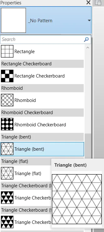
3. After dividing the form, select the divides surface tool and select the Triangle bent pattern
RESULT:
- The conceptual mass has been created successfully and applied to the triangular bent panel
QUESTION:-5
Use Dynamo to work on developing a Parametric Stadium. List your parameters and use the visual programming approach to complete the modeling, You can use the concepts discussed in the parametric high-rise tower in class for reference.
ANSWER
AIM:To develop a parametric stadium using dynamo in Revit
INTRODUCTION:
- Parametric design is a design method where features (such as building elements and engineering components) are shaped according to algorithmic processes, in contrast to being designed directly. In this method, parameters and rules determine the relationship between design intent and design response. The term parametric refers to input parameters fed into the algorithms.
- The following elements define parametric architecture:
- Blending complexity and variety, thus rejecting homogenous utilitarianism
- Shared priorities involving urbanism, interior design, an architectural wonder, and even fashion
- The idea that all design elements are interdependent and adaptable
- A skew towards computerized, algorithmic design processes
NODES USED:
1. Integer slider
2. Code block
3. Coordinate system by origin
4. Rectangle by width and length
5. Point origin
6. Vector Z axis
7. Geometry rotate
8. Polysurface by loft
PROCEDURE:
STEP:-1
1. Open Revit software and select the New template file
2. Select the Template file as Imperial-Architectural and press OK
STEP:-2
1. Go to the manage tab and select the dynamo option
2. It will open the dynamo software in a new window
STEP:-3
1. After opening the dynamo software, click on New file under the File tab
STEP:-4
1. Select the integer slider by searching the integer slider in the library search box
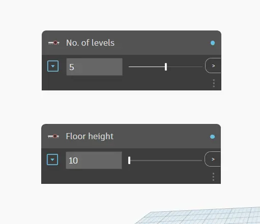
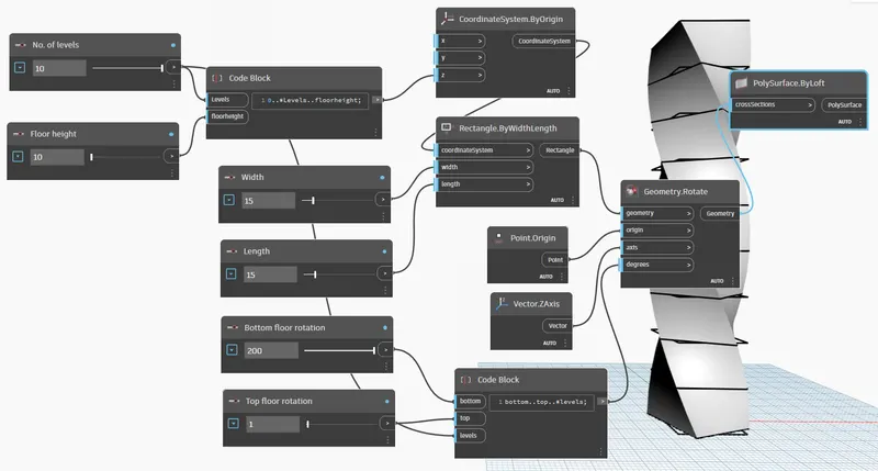
2. Select two sliders and give the name as no. of levels and floor height respectively
3. Then give the input values for levels as 5 and floor height as 10
STEP-5
1. In the library search box, type code block and select the code block node
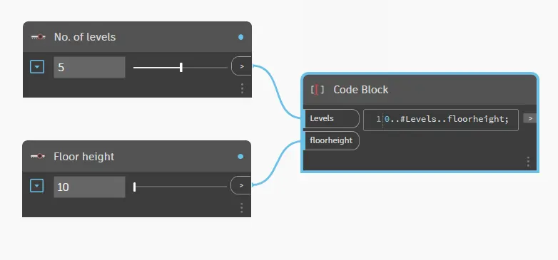
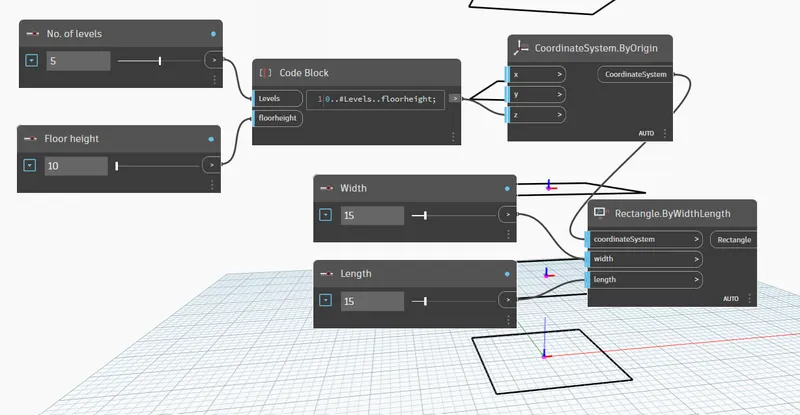
2. Give the code as 0..#levels..floorheight as shown in the figure below
3. Then connect the wires from the no. of levels to the levels and floor height to the floor height
STEP:-6
1. In the library search box, type coordinate system by origin and select that node
2. Then connect the wires from the code block to the Z coordinate
3. Now we to add two integer sliders for the width and length of the rectangle
4. In the search box, type integer slider and select the two sliders
5. Give the names as width and length respectively
6. Give the input values for width as 15 and length as 15
7. In the search box, type rectangle by width length and select that node
8. Then connect the wires from coordinate system to coordinate system, width to width, and length to length as shown in the figure below
STEP-7
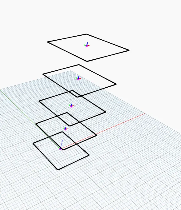
1. Hence the rectangles have been created as shown in the figure below
STEP:-8
1. In the search box, type integer slider, and select two sliders
2. Give the name of the sliders as bottom floor rotation and top floor rotation respectively
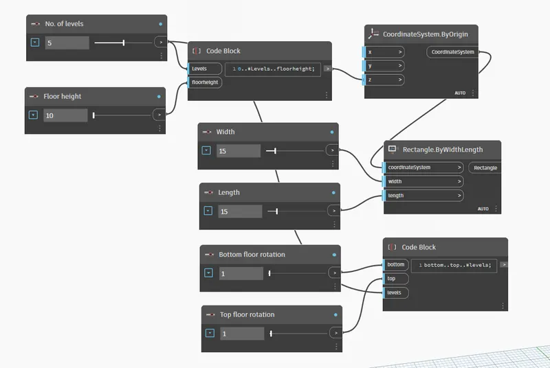
3. Then give the input values for the bottom floor rotation as 200 and top floor rotation as 1
4. In the search box, type code block and give the code as bottom..top..#levels as shown in the figure below
5. Then connect the wires from the bottom floor rotation slider to the bottom, the top floor rotation slider to the top, and no. of levels to levels
STEP:-9
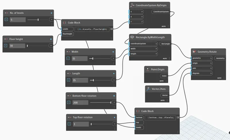
1. In the search box, type point origin, and vector Z Axis
2. Then select the point origin node and vector Z Axis node
3. Again search for geometry rotate and select the node
4. Then connect the wires from rectangle by width length to geometry, point origin to origin, Vector Z axis to axis, and code block to degrees as shown in the figure below
STEP:-10
1. Now we have to create a Surface out of the Parametric design
2. In the library search box, type poly surface by the loft and select the node
3. Then connect the wire from the geometry to the poly surface by loft as shown in the figure below
STEP:-11
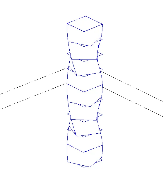
1. To Cross-check this, open the Revit software and go to 3d view
2. Hence the parametric stadium has been created in the Revit using Dynamo
RESULT:
- The parametric stadium has been created successfully using dynamo in Revit