Creating Conceptual mass in REVIT and Creation of Sinusoidal curve and a Parametric stadium using Dynamo
1) Using Dynamo create a set of sinusoidal points and create a curve and create a surface out of the curve.
Aim: To create sinusoidal points and to create a curve and surface out of the curve.
Introduction: The dynamo is a visual programming software which process the input given and output is produced. Dynamo is used for creating structures based on the coordiate points and to create a surface based on the points. The sinusoidal points can be created by mathematical operations.
Steps:
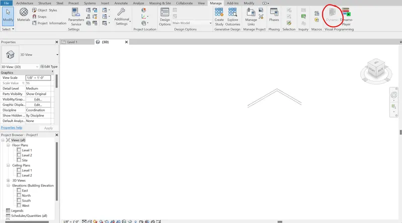
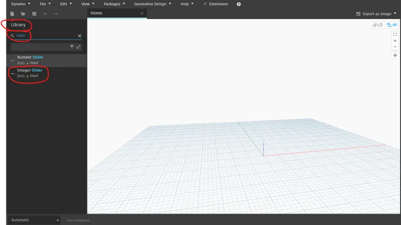
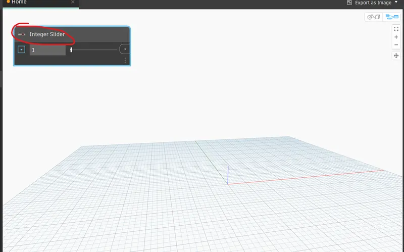
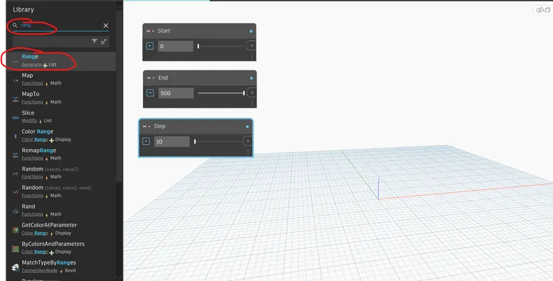
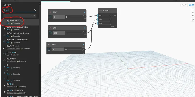
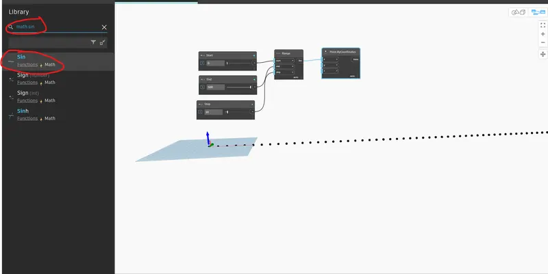
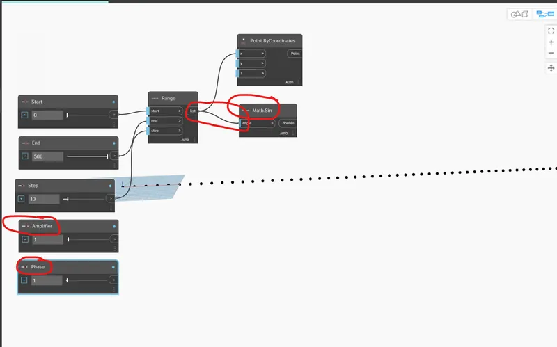
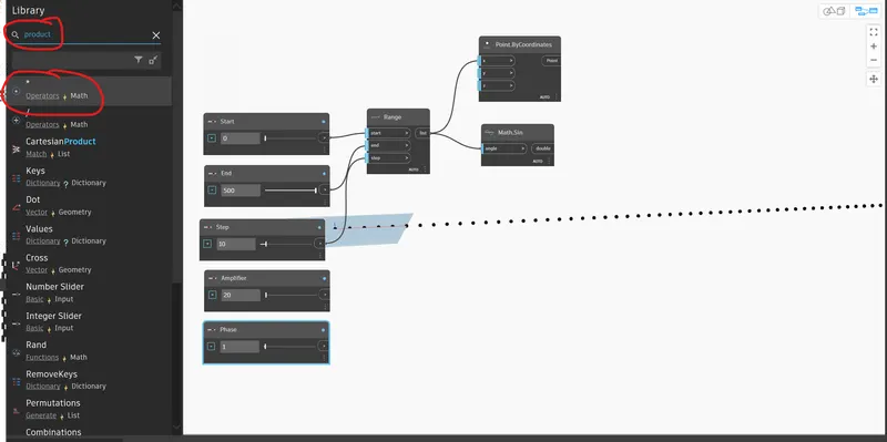
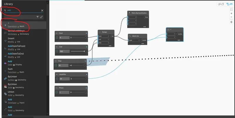
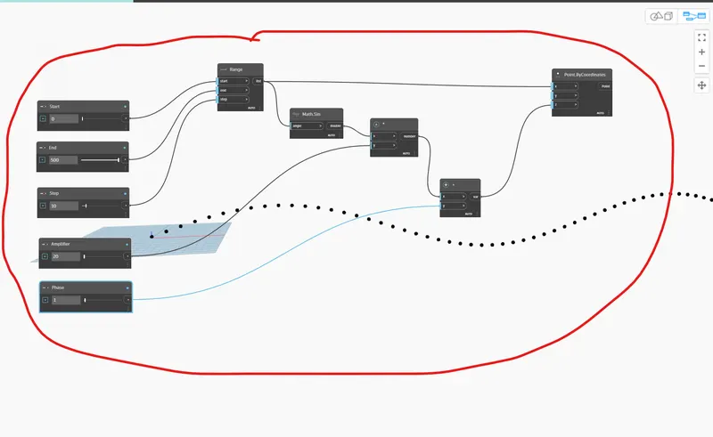
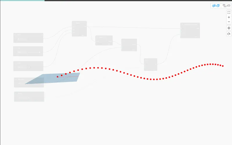
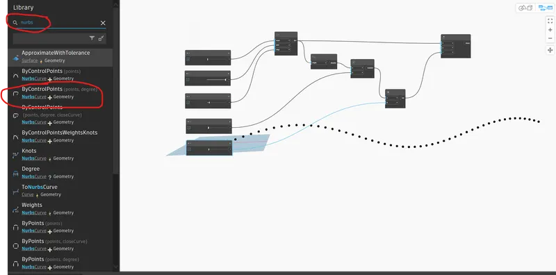
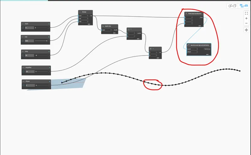
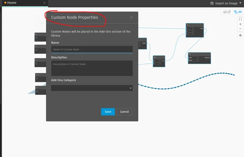
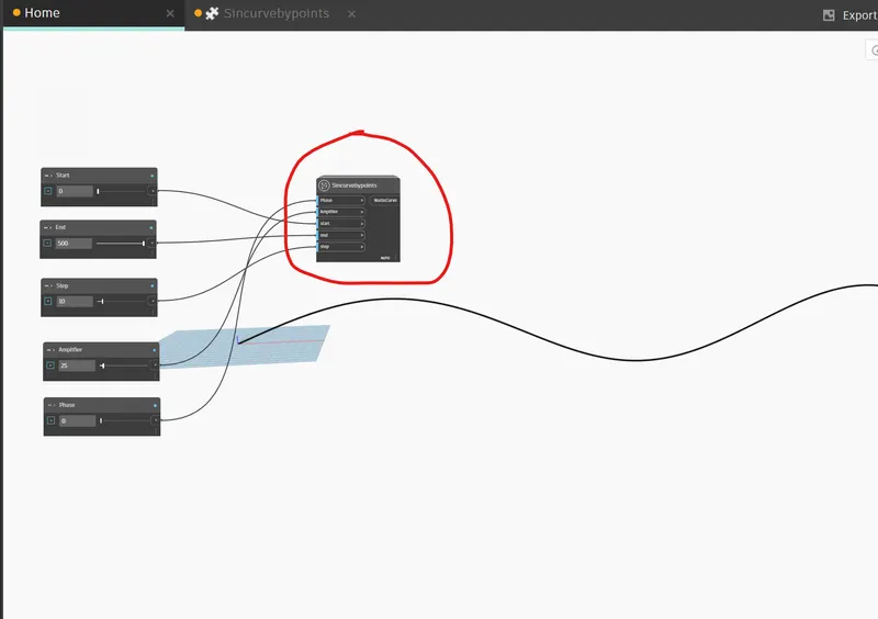
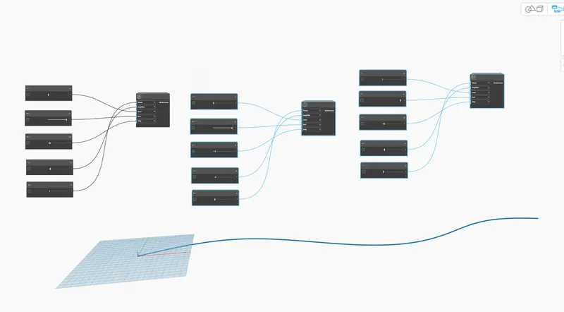
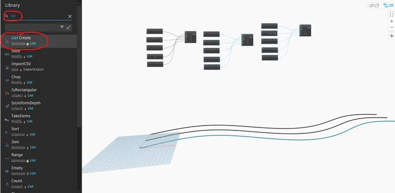
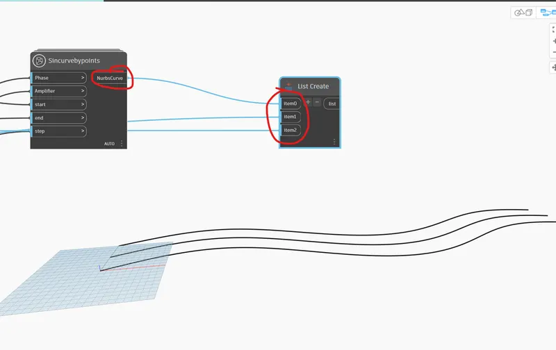
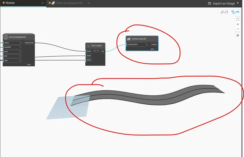
- Initially after opening the revit project template, dynamo is selected from the manage tab of the ribbon and a new dynamo project is created.
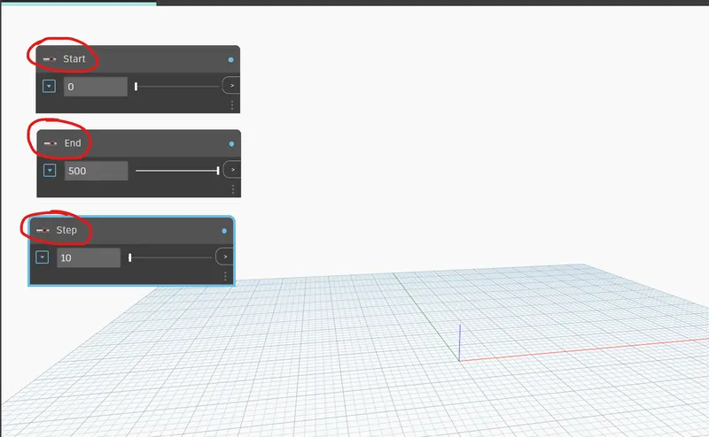
- Then in the search option from the left of the dynamo screen sliders are searched and included and five of them are included.
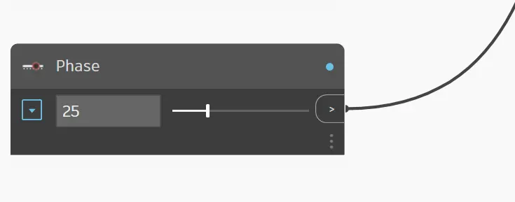
- Five sliders are included for the purpose start,end,step for points amplifier and phase for the sinusoidal curve
- Then Range is included for the points and the range is connected with sliders of start,end,step
- Then point by coordinates command box is include and it is connected with range in x axis where the points are needed.
- Then math.sin command box is included to have sinusoidal formula and it is connected with range command
- Then product and add mathematical operation commands are included
- Product command is connected with amplifier slider and math.sin formula to form the sinusoidal curve points
- Then add command is connected with the product coomand output and phase slider to provide a phase for the curve and the output is connected to the point by coordinates command and sinusoidal points are created
- Futhermore Nurbs by curve command box is included and it is connected with point by coordinates command output and the sinusoidal curve is thus formed
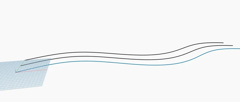
- Then for creating similar curves the commands which process the input are grouped and created as a custom node and the commands are copy pasted a two times to create a further two more curves
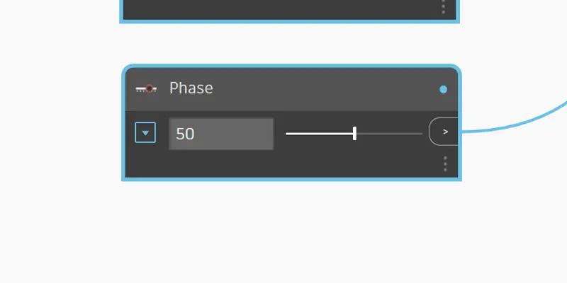
- The phase is increased in the slider to place the curves at a definite distance.
- Then list command is created to list the curves created and it is connected with the nodes created.
- Finally surface by loft command is included and connected with list.create command output and a surface is created.
Results: Thus sinusoidal surface is created sucessfully using the curve and points created.
2) Create a conceptual layout of floor plan in dynamo . Using the tools available in dynamo link the lines to appropriate model elements in Revit by choosing the wall types and wall parameters. Make use of the sliders to slide through the height of the wall and length of the wall.
Aim: To create a conceptual layout of floor paln in dynamo and to create model elements in lRevit using the tools available in dynamo link
Introduction: The creation of conceptual layout is done using the points created and connecting them using the lines. Since revit and dynamo are connected the model elements can be included in the dynamo itself and the types of model elements can also be fixed in the dynamo. The heignt and length of the wall can also be edited in the dynamo using sliders.
Steps:
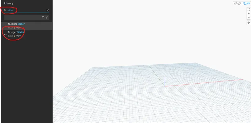
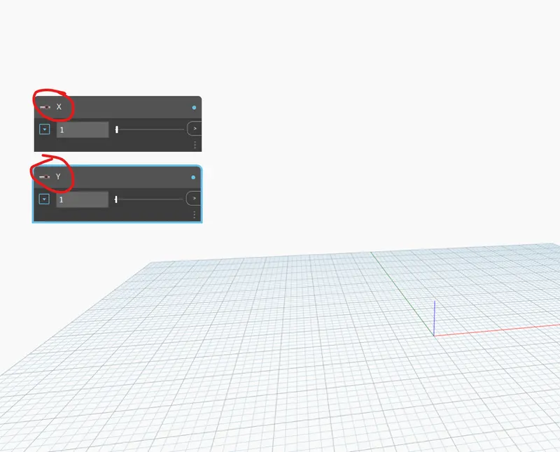
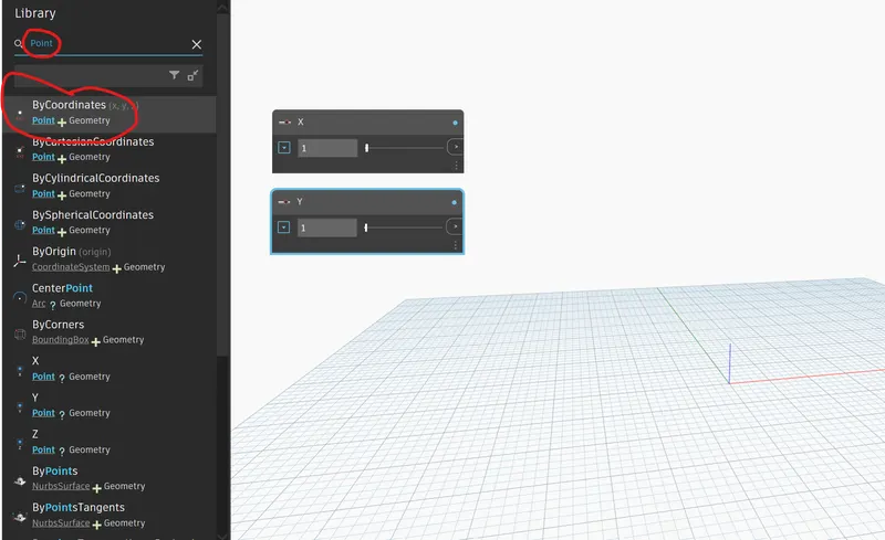
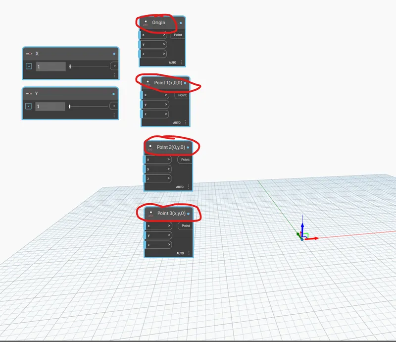
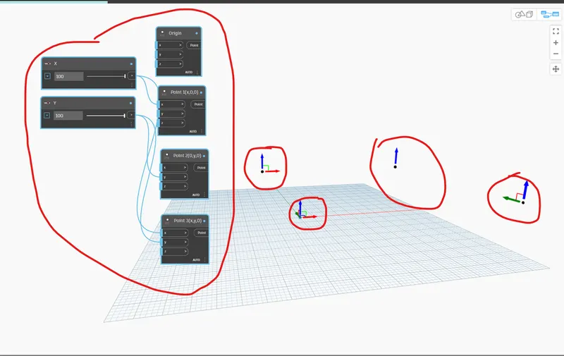
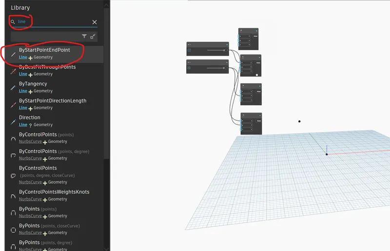
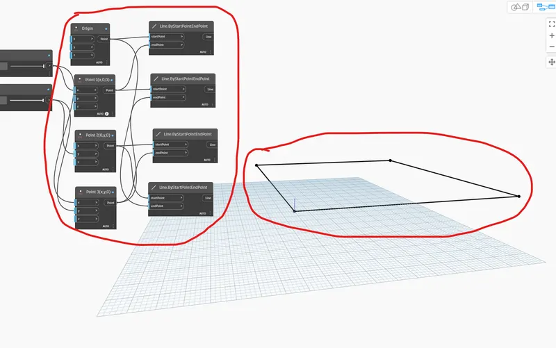
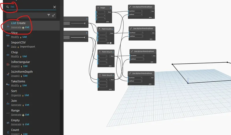
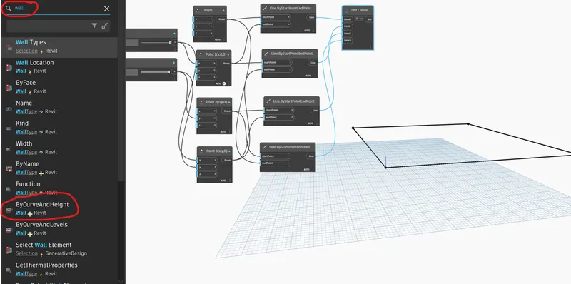
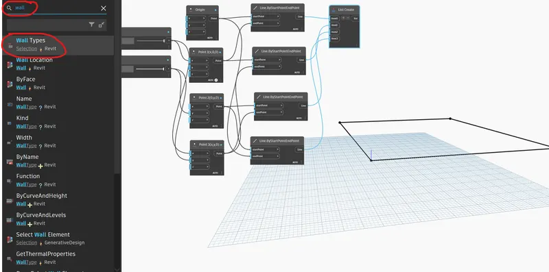
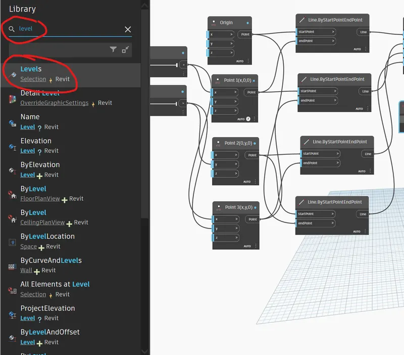
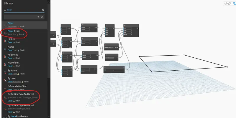
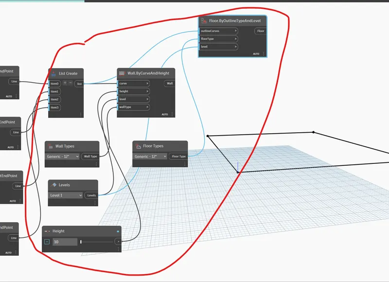
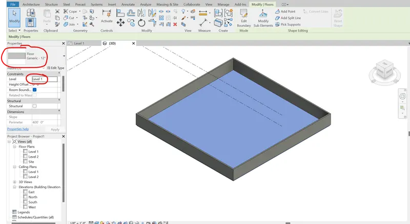
- Initially two sliders are included for x and y axis and the values are placed as 100
- Then four point by coordinates command boxes are included and are named as origin,point 1(x,0,0),point 2(0,y,0),point 3(x,y,0) inorder to place the points respectively and the sliders are connected as per the point of placement like x slider is connected to the point 1,y to point 2 and both sliders to point 3 and the points are created.
- Then line command is inserted and it is connected with respective point by coordinates to start point and end point which connects the points with lines
- Then list.create command to list the lines created and connected with line commands
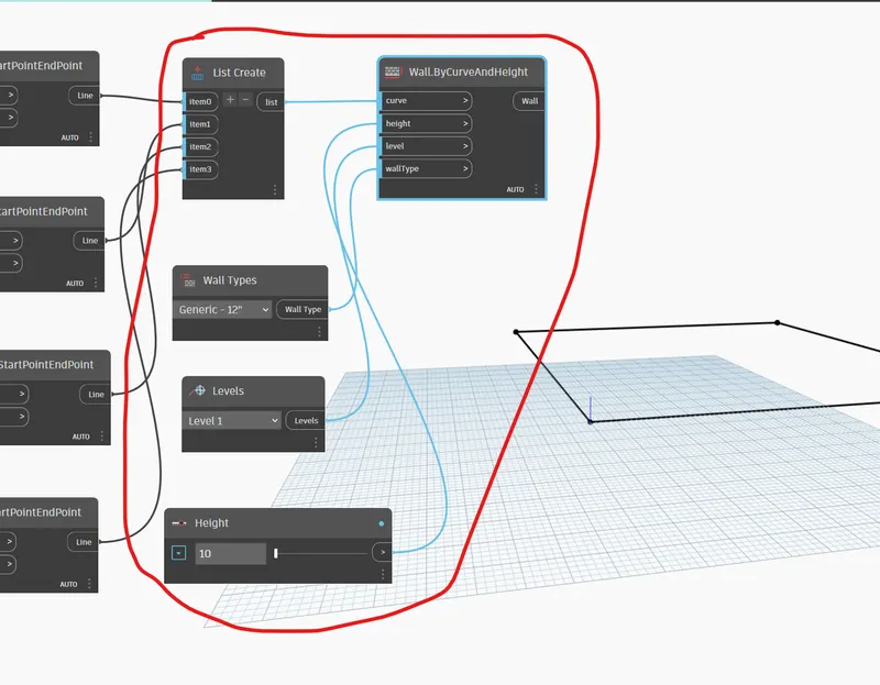
- Furthermore wall.by curve and height command box is included and a slider is included for height of the wall
- Then wall.types and levels command box is included for assigning the type of wall and the level in which the wall is to be created respectively
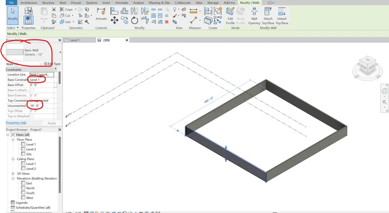
- Then the wall.by curve command is connected with the height,type,level and the output of list.create and the wall is created and reflected in the revit software
- The floor element is added by floor.by outlinetype and level command
- Then floor types command is included to assign the type of floor element to be included
- Then the floor.by outlinetype and level command is connected with type,level,list.create output and the floor element is created and reflected in revit as per the layout.
Results: Thus a conceptual layout and the model elements are created sucessfully.
3) Create an array of model elements in Revit. Use dynamo to vary the properties of model elements by using the slider or code block
Aim: To create an array of model elements in revit and to use dynamo to vary the properties of the model elements.
Introduction: Dynamo is not only used for the purpose of creating strcutures and connect it to revit but also to vary the properties of model elements created in revit simultaneously which saves the time. In revit the model elements has to be selected and the properties has to be changed individually whereas the properties can be changed simultaneously.
Steps:
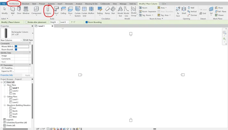
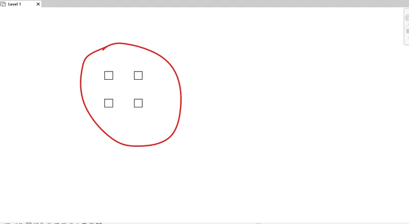
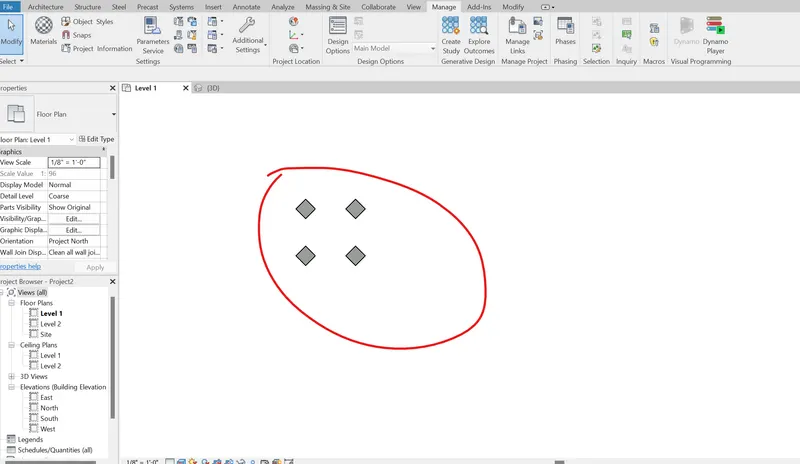
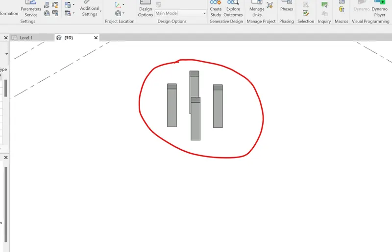
- Initially four architectural columns are created in the revit from the column option of the architectural tab
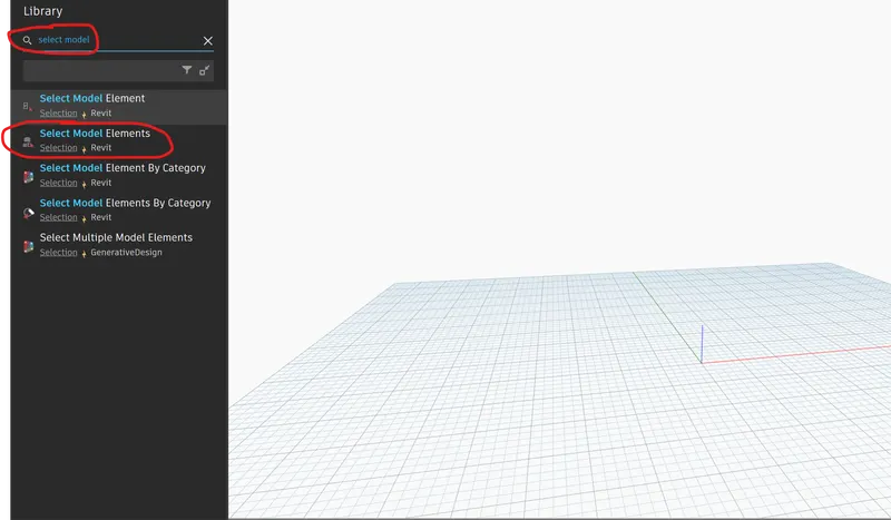
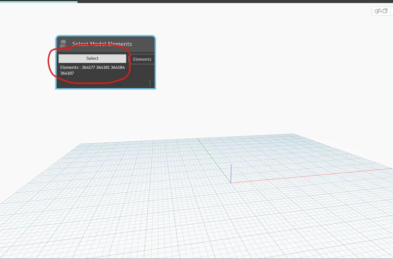
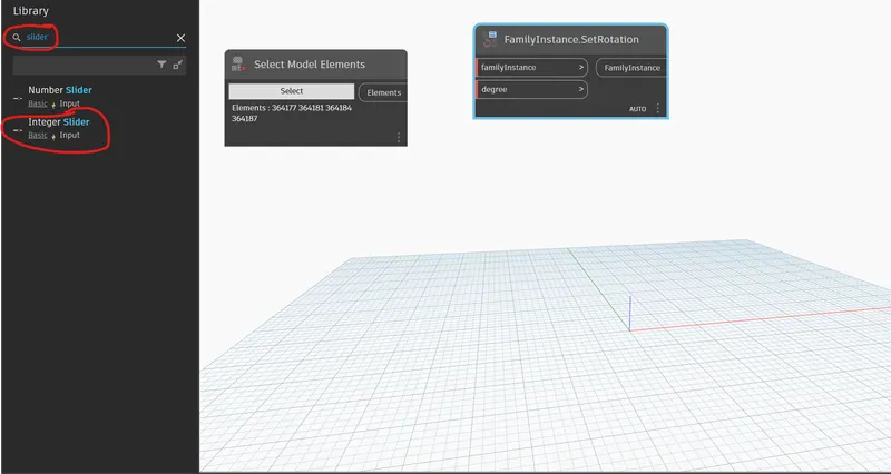
- Then dynamo screen is opened and select model elements command is included and using the select option the model elements are selected in the revit screen
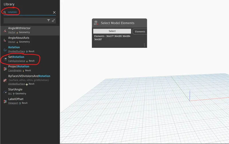
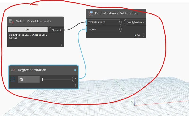
- Then set rotation command is included and a slider for degree is also included
- Then select model elements and degree slider is connected with set rotation
- Then by changing the degree using the slider the model elements can be rotated and it is reflected in the revit
Results: Thus array of model elements are created and the properties are changed using the dynamo sucessfully.
4) Create a conceptual mass in Revit and develop a parametric column by dividing the surfaces and apply the concepts similar to used in parametric walkway modelling. Use triangular bent or square shaped panels to add finish to the parametric column
Aim: To create a conceptual mass in Revit and develop a parametric column by dividing the surfaces
Introduction: The revit and dynamo programming is not only used for creating conventional structures but also for the purpose of creating parametric structures that are unusual than the normal structures which are mostly used for aesthetic purpose and as bus shelters and as walkthrough structures.
Steps:
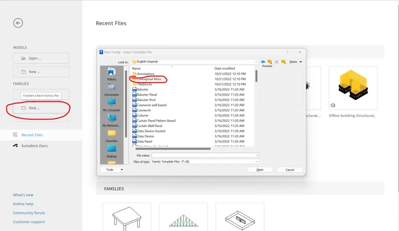

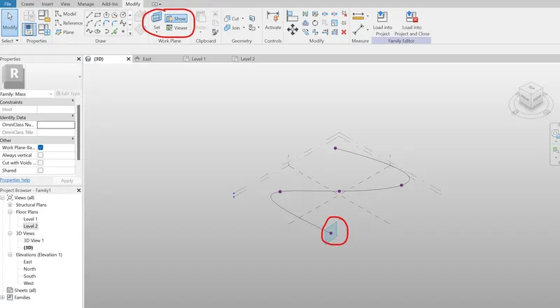
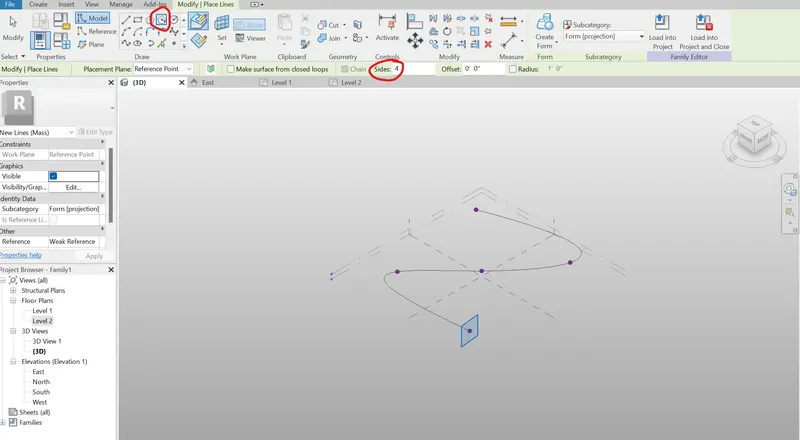
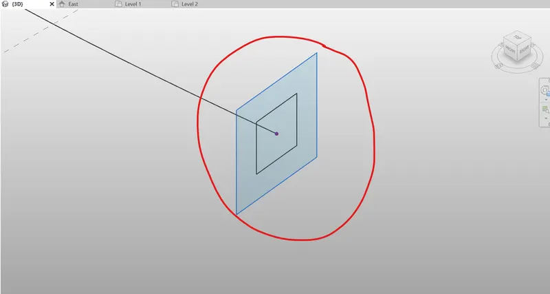
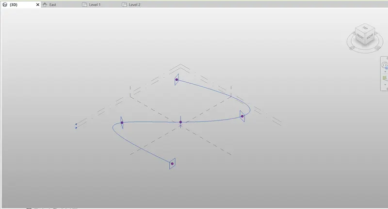
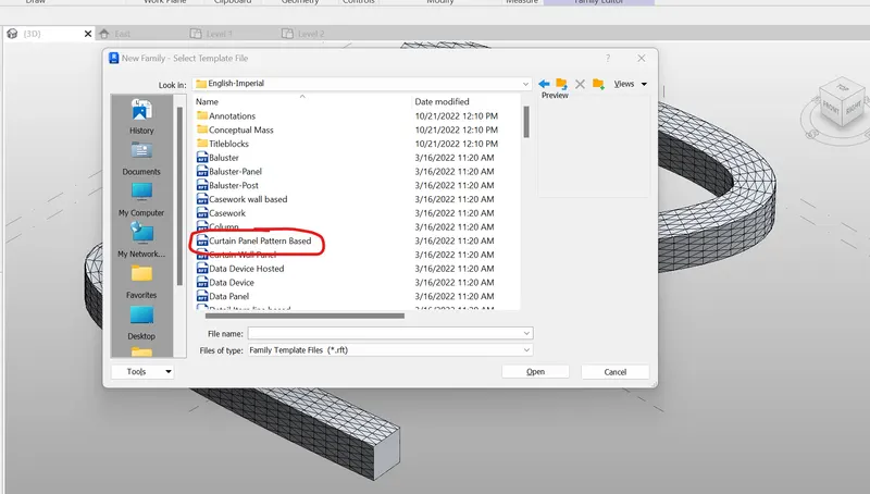
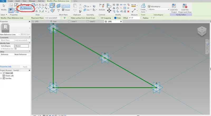
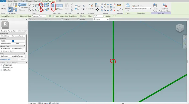
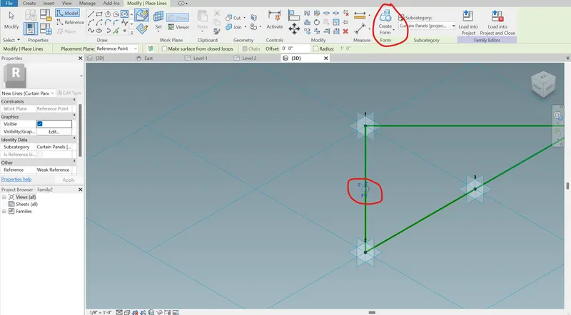
- Initially in the revit home page new>conceptual mass option is selected.
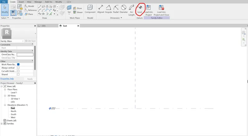
- Then in the elevation a level is added at a height of 10'
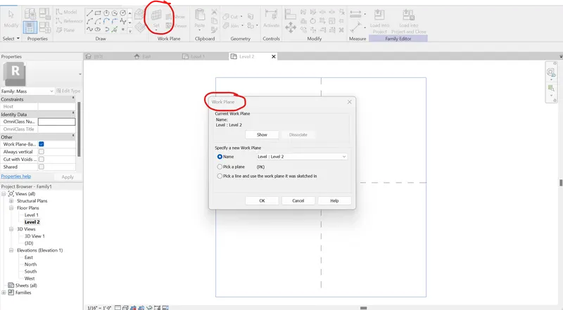
- Further the level 2 is set as work plane
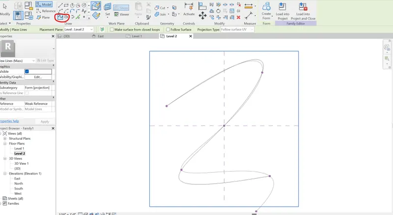
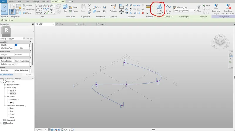
- Followed by model option and spline curve tool a spline curve is drawn for a parametric model
- Then at each points of the curve work plane is set and a inscribed polygon of 4 sides is created of a size of 10' on the centre of the work plane
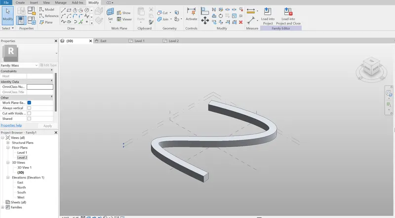
- Then the curve is selected and create form option is selected thus a solid rectangular like walkthrough is created
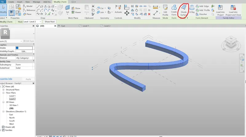
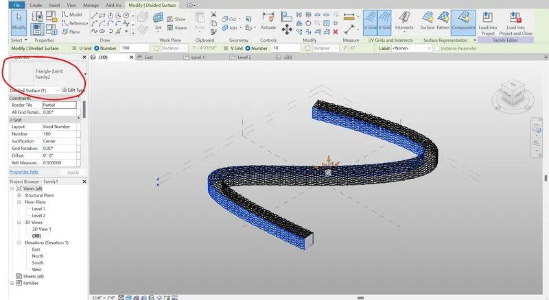
- Then the created surface is selected and divide surafce option is selected to divide the form into different surfaces
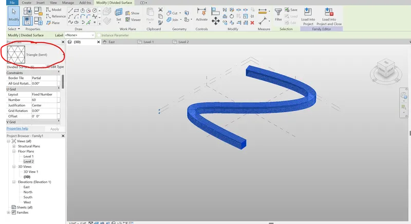
- Then a pattern is selected for the divided surfaces
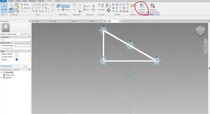
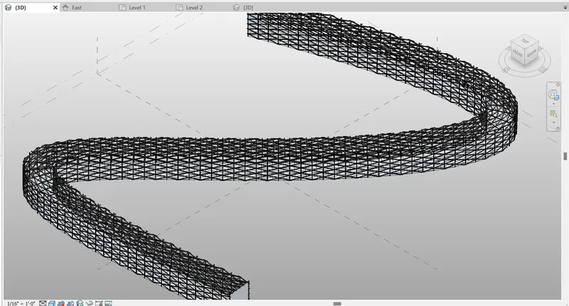
- Then a new family of curtain walls is created for the surfaces using the similar procedure and loaded into project and the pattern of the walkthrough structure is changed to curtain wall based pattern and the parametric structure is created.
Results: Thus a parametric walkthrough structure is created sucessfully.
5) Use Dynamo to work on developing a Parametric Stadium. List your parameters and use the visual programming approach to complete the modelling, You can use the concepts discussed in parametric high rise tower in class for reference.
Aim: To create a parametric stadium using dynamo.
Introduction: Dynamo is vital programming software which paves the easy way of designing a parametric building. The parametric design is more tenacious without dynamo as it is not a conventional type of structure and takes more to model in conventional method and with dynamo the structure can be created easily. The parameters included in this design are the levels of the project,floor to floor height and rotation of the building.
Steps:
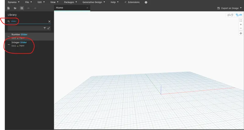
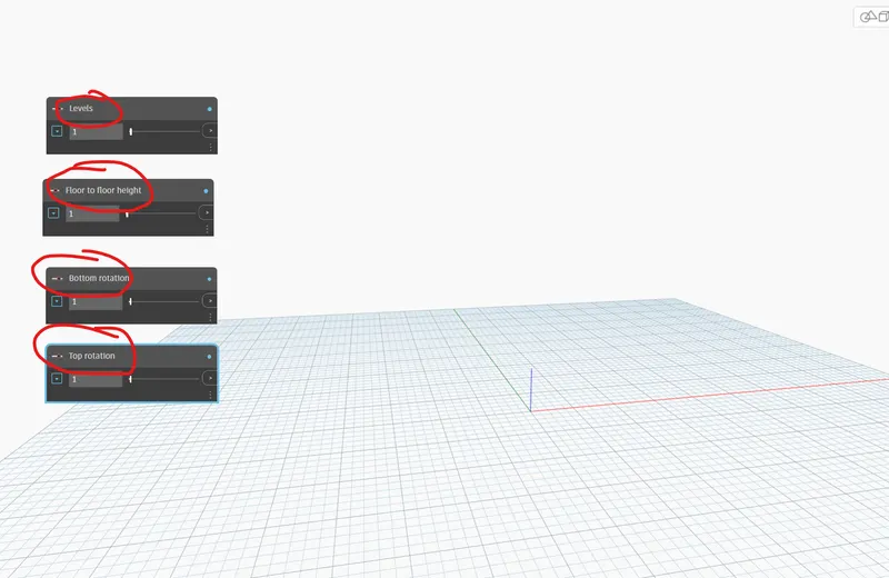
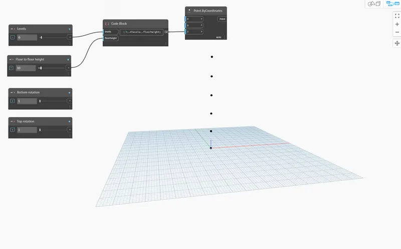
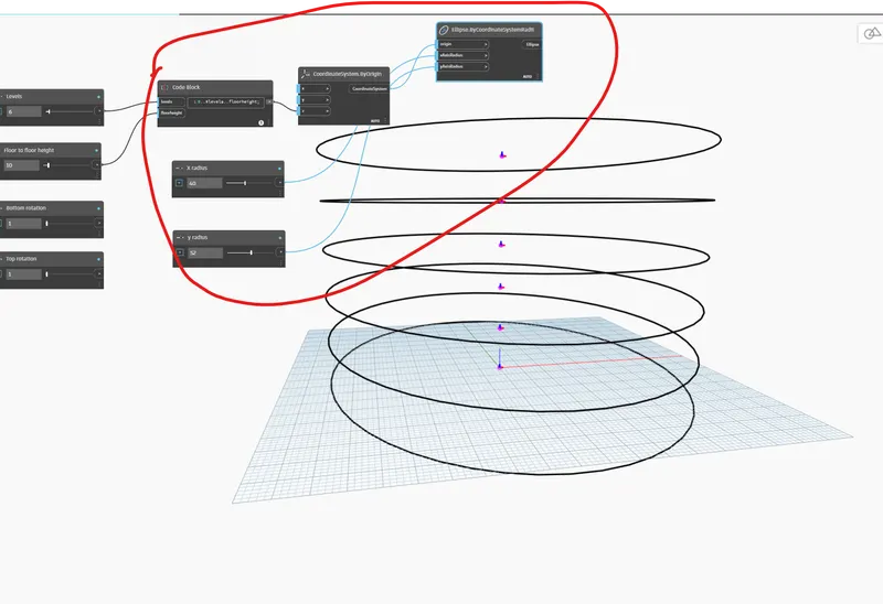
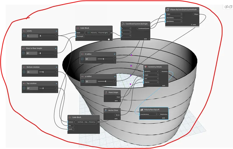
- Initially four sliders are inserted for parameters like levels,floor to floor height,bottom rotation,top rotation of the building.
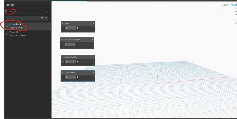
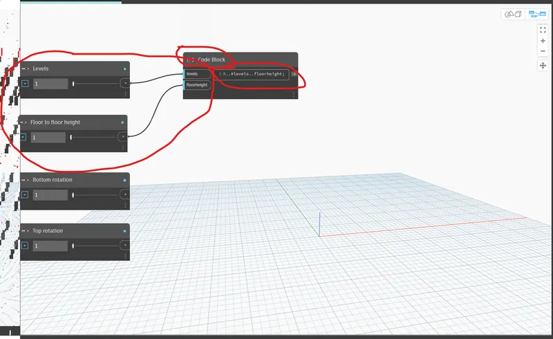
- Then a code block is inserted and the code is created for levels and floor to floor height of the building
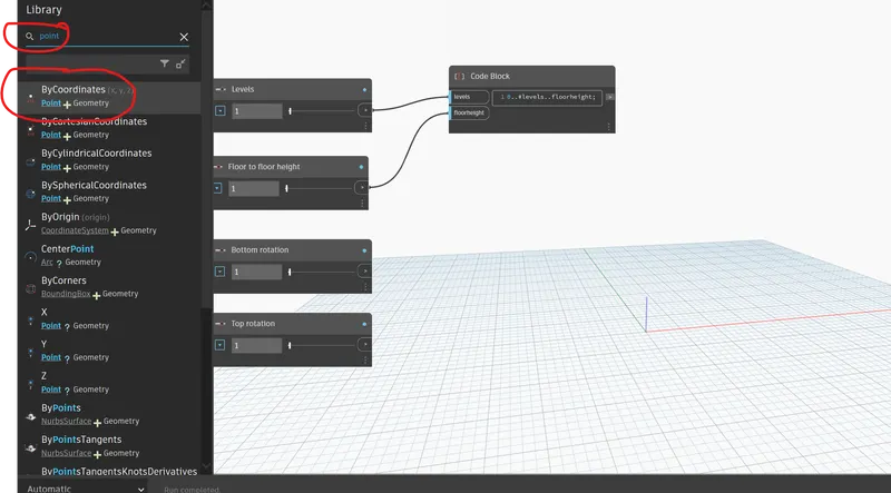
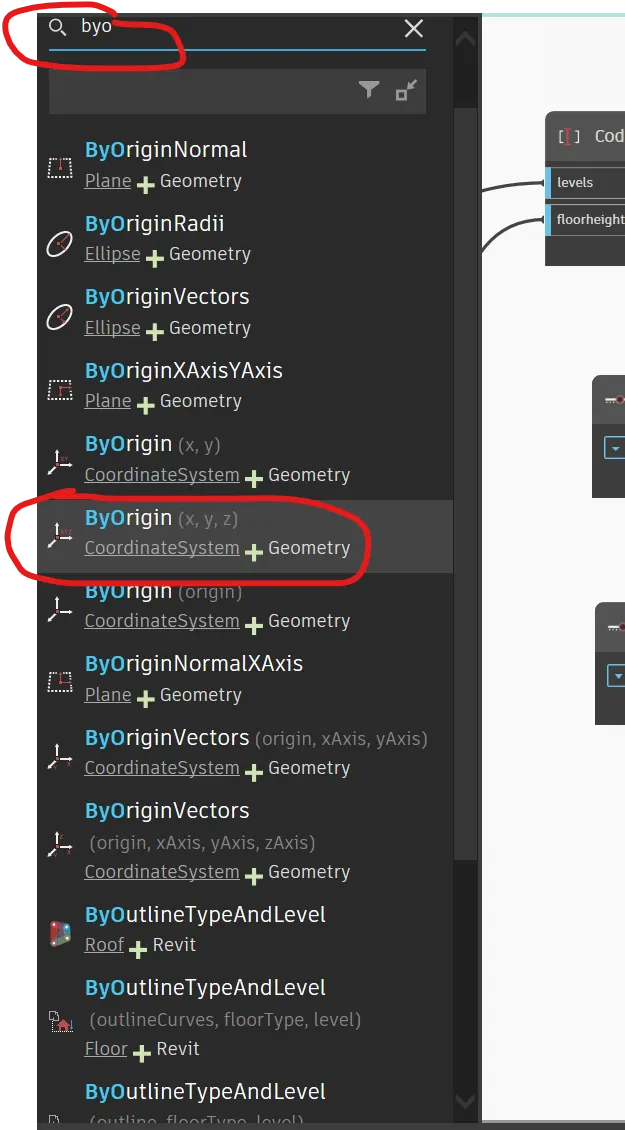
- Then point by coordinate system command is inserted and it is connected with the code block output created and coordinate system is created in the z axis based on the input of levels given.
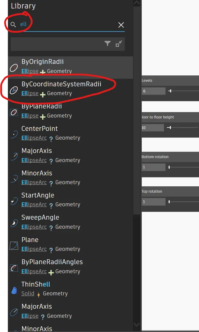
- Furthermore, the shape of the stadium is assigned to be elliptical and ellipse.bycoordinatesystemradii command is inserted and connected with point by coordinate system
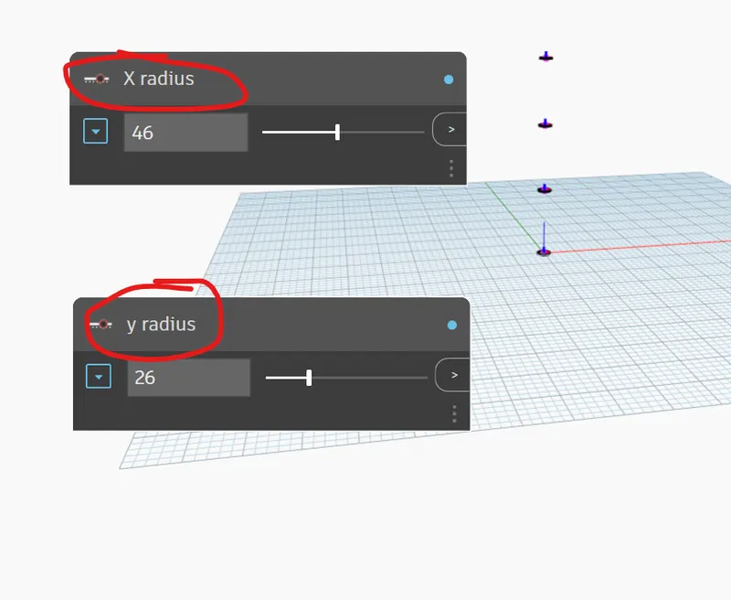
- Then 2 sliders are inserted for x radius and y radius of the ellipse and are connected to the ellipse.bycoordinatesystemradii and required shape for the ellipse is fixed
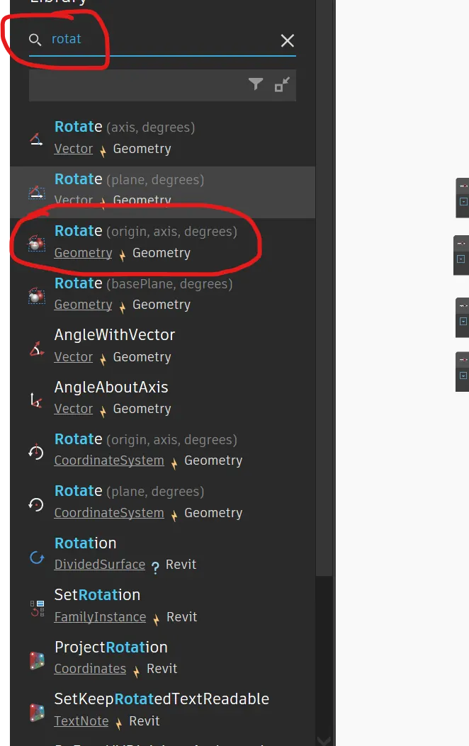
- For providing rotation in the structure geometry rotate command which is based on the inputs of geometry,origin,axis and degrees
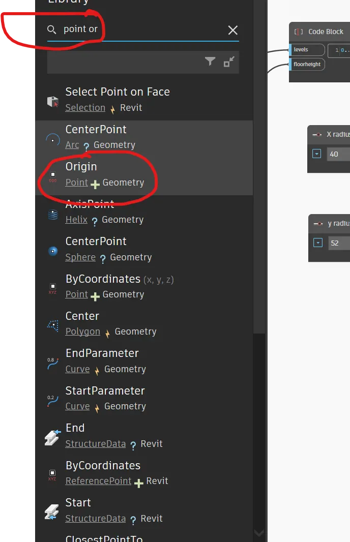
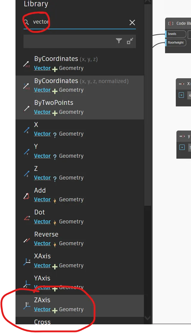
- The input for geometry is inserted from the ellipse.bycoordinatesystemradii and for other inputs point.origin command,vector.zaxis command and for degrees a code block is inserted
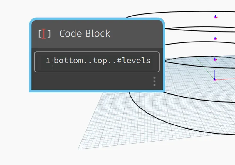
- The code inserted for the code block is bottom,top and levels and the sliders of bottom rotation,top rotation, levels are inserted to the code block and the code block output is inserted to the degree input of the geometry rotate
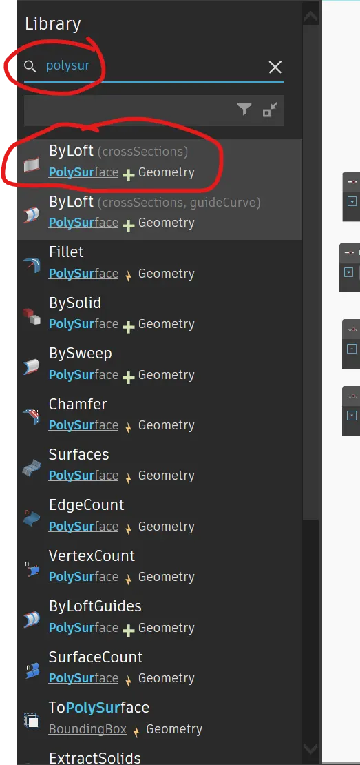
- Finally for creating surface, polysurface by loft command is inserted and the input is connected with the output of geometry by rotate and a surface is created.
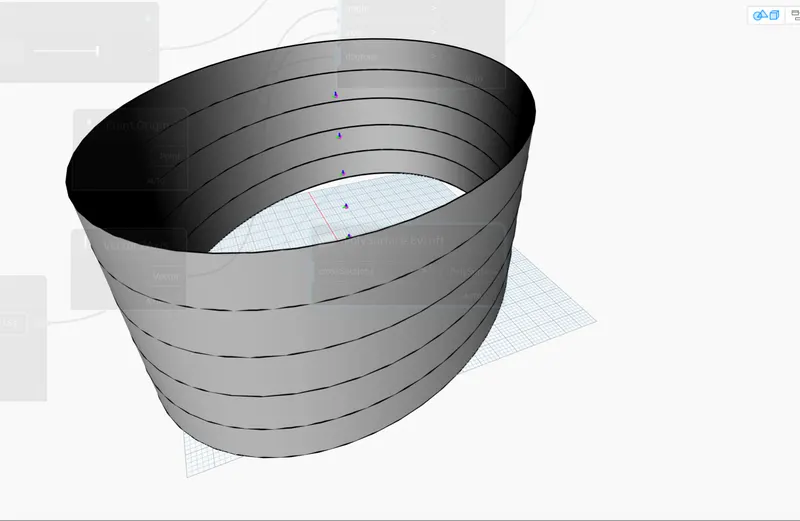
- The surface can be rotated and elongated as per the requirement using the sliders for rotation and radius and the levels and floor to floor height of the structure can also be edited as per the requirement using the sliders and a parametric elliptical stadium structure is created.
Results: Thus a parametric elliptical shape stadium is created sucessfully using the dynamo programming.