Creating Conceptual mass in REVIT and Creation of Sinusoidal curve and a Parametric stadium using Dynamo
1. Using Dynamo create a set of sinusoidal points and create a curve and create a surface out of the curve.
AIM:- To create a set of sinusoidal points, create a curve and to create a surface out of the curve.
INTRODUCTION:-
- Autodesk Dynamo allows you to build custom tools that can help you solve modeling challenges with greater efficiency—and it's already included in your Revit software. If you've been meaning to learn how to leverage Dynamo in your workflow, this course can help you get started by exploring practical applications of this powerful tool.
- Paul F. Aubin provides several examples of how to use Dynamo to speed up common procedures, including how to rename multiple project views and place component families along a path. Plus, he demonstrates how to use Dynamo to place adaptive component families.
- Dynamo is an open source visual programming language for Revit, written by designers and construction professionals. Its a programming language that allows you to type lines of code; while also creating an algorithm that consist of nodes.
- Using dynamo work can be carried out with enhanced BIM capabiilities in Revit. Dynamo and Revit an together be utilized to model and analyze complex geometries, automate repetative processes, minimize human error and export data to exer and other file types.
- Dynamo can make the design process more efficient with an intuitive interface and many pre made scripting libraries availabe as well.
- The user interface for dynamo is organized into five main areas, largest being the workspace where programms are processed and this user interface sections include.
- Main Menu
- Toolbar
- Library
- Work Space
- Execution Bar
- The workspace is the place where designers develop visual programs but it is also the place where any elaborate geometry is previewed.
- Conceptual mass of a building contains different types of parameters like level, floor area, floor perimeter and architect can generate early quanties takeoff from the mass.
- In Bim modelling services the conceptual mass of a building can be exported to to any other format for performing early energy analysis.
PROCEDURE:-
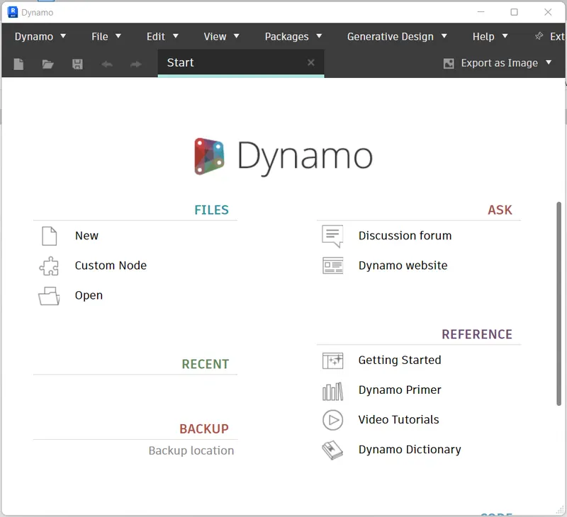
- Open the Revit software, Select architectural template and click on the dynamo option in the manage toolbar.
- After opening the dynamo, double click on the dynamo screen.
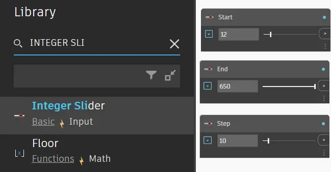
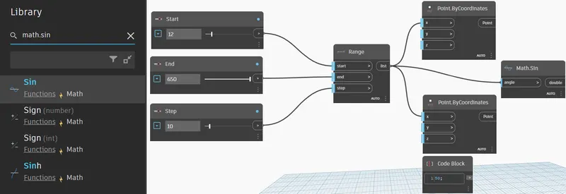
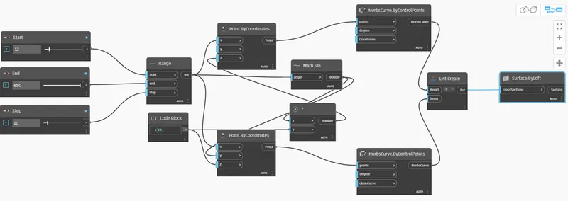
- In the library search integer slider and create 3 sliders rename them as Start, End and Step.
- Give the values.
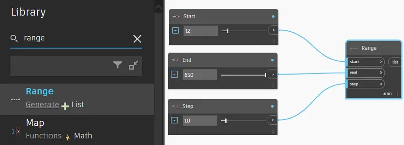
- In the library search range and connect all three sliders to the range appropriately.
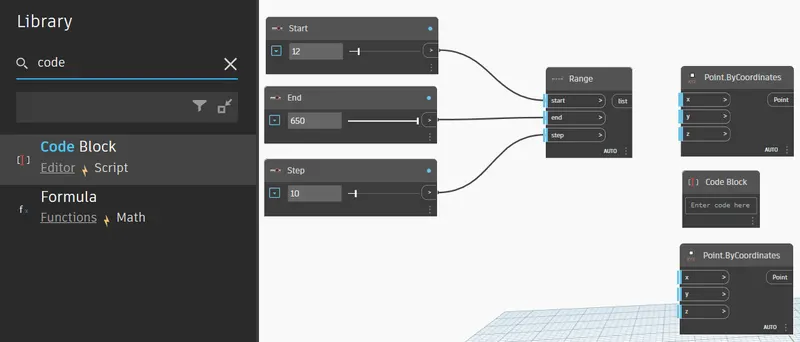
- In the library search Point by co-ordinates and search code block.
- Copy the Point by co-ordinates and paste it.
- Click on it connect range to the X-co-ordinates as shown.
- In the library search sine curve by the command math.sine.
- Connect the Range to the sine curve.
- In code block enter the code block number as 50;
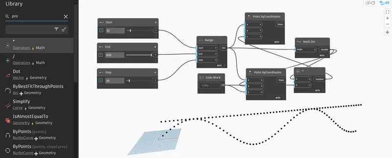
- Create product function by using product and connect the sine to the X-co-ordinates product function.
- Connect product function Y-co-ordinates to code block 50;
- Connect bottom one dialogue box of Point.ByCoordinate - Z to Code block 50;
- Connect bottom one dialogue box Point.ByCoordinate - Y to Math.Sin.
- Connect Top one dialogue box Point.ByCoordinate - Z to Product function.
- Thereby, sinsoidal points are created as shown.
To Create Line and Curve out of set of sinsoidal points created:-
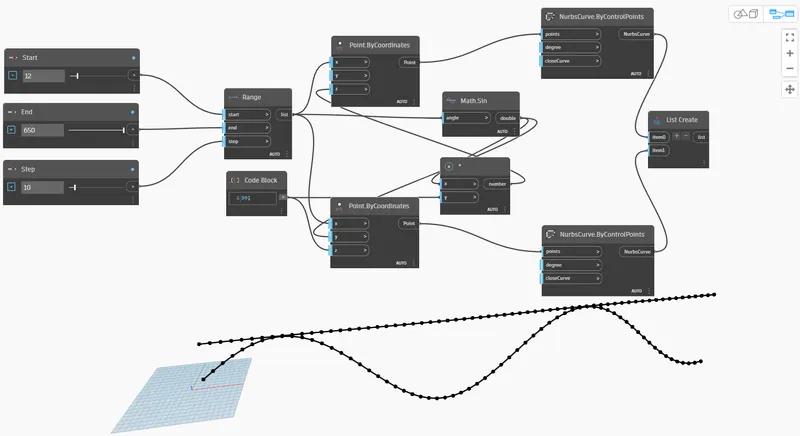
- Create curve by using nurbscurve by control points. After that copy nurbs curve and paste it on the vottom side of screen. And also create the list to add the items.
- Connect point in NurbsCurve.Bycontrolpoints to point in Point.ByCoordinate.
- Repeat the same to the top one.
- In Create list click on add buttom to get item 0 and item 1.
- Connect both Nurbscurve to item 0 and item 1.
- Thereby, using sinsoidal points created both lines and curve is created as shown.
To create a surface out of the curve created:-
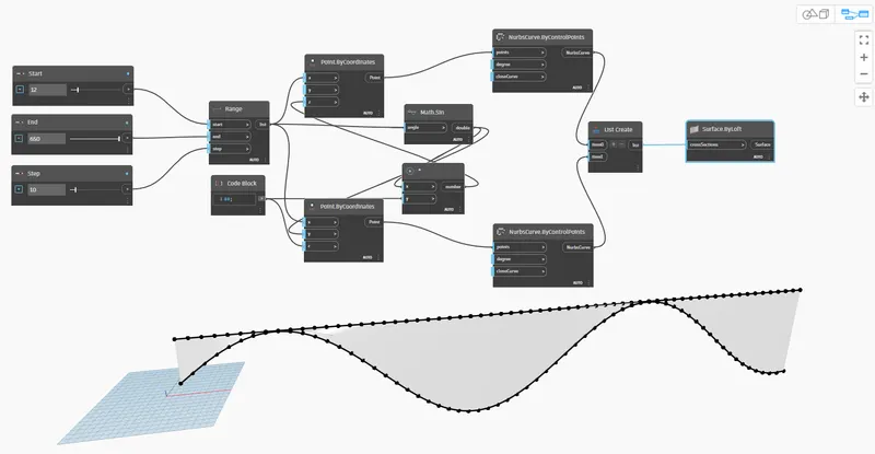
- To create Surface.Loft cross section from library and connect List create to Surface loft cross section.
- Thereby, using sinsoidal curve created Surface is created as shown.
RESULT:-
- A set of sinusoidal points have been created
- Sinusoidal curve connecting points is created
- Surface is created out of the curves
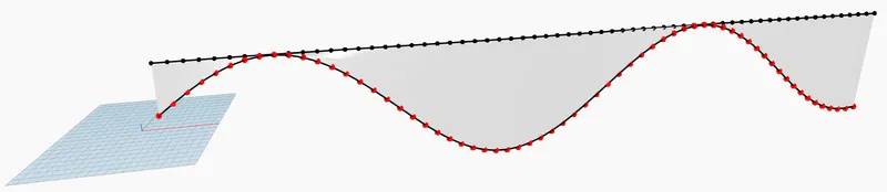
- 3D view of Dynamo figure is shown in revit
- The sinusoidal points, sinusoidal curve and surface are created as shown.
- Surface is in Pale pink colour.
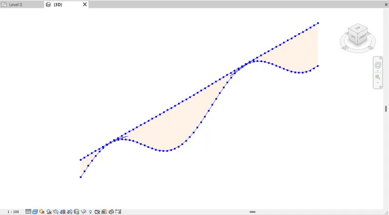
_____________________________________________________________________________________________________
2. Create a conceptual layout of floor plan in dynamo. Using the tools available in dynamo link the lines to appropriate model elements in revit by choosing the wall types and wall parameters. Make use of the sliders to slide through the height of the wall and length of the wall.
AIM:- To create a conceptual layout of a floor plan in dynamo.
INTRODUCTION:-
- Create conceptual masses and adaptive geometry to be loaded into the Revit project environment.
- The CDE provides flexibility early in the design process to express ideas and create parametric massing families that can be integrated into building information modeling (BIM).
PROCEDURE:-
- Open a new architectural template.
- Change the units to imperial.
- Go to manage tab and open the dynamo --> New.
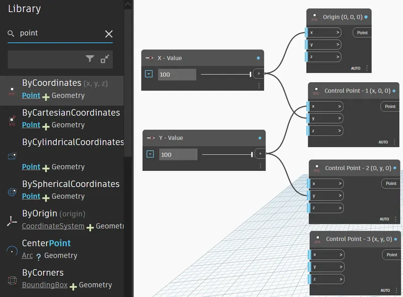
- Create two integer sliders and name them as x and y, and give the minimum integer value as 100.
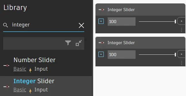
- Inorder to create the wall first we have to create four control points.
- For this, search points by coordinates in the search panel of the library.
- 1st one is named as origin (0,0,0) and the rest is named as control point 1(x,0,0), control point 2(0,y,0) and control point 3(x,y,0).
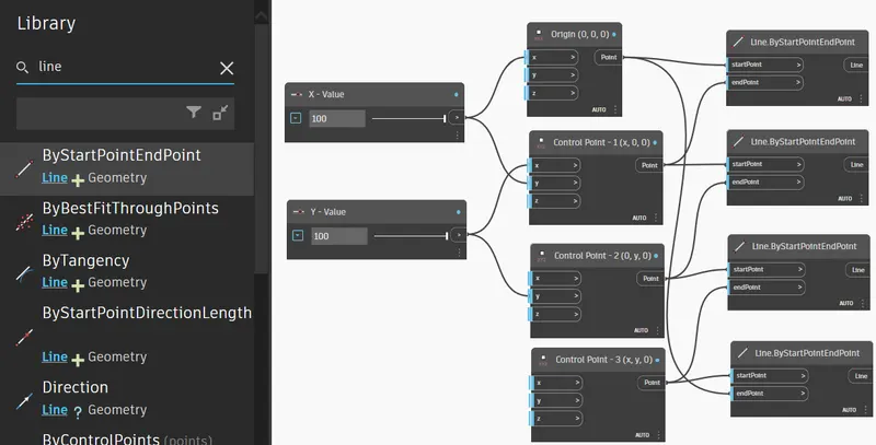
- Now, we have to connect these points by a line.
- So for this, search line by start and end point and insert 4 blocks.
- The input for these blocks are the points created previously.
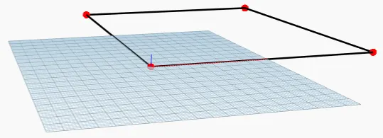
- Hence, the layout of the floor plan is obtained.
- Now, search wall in the panel and choose wall by curve and height.
- So, for this input required are curve, height, level and wall type. Inputs are given as follows:
- For curve, combine all the four lines in a list by choosing listcreate.
- For height, another number slider is chosen and name it as height.
- For level, search level in the search panel it will contain the levels availbale in your revit folder. Then choose the level in which you want to place your structure.
- For wall type, search wall type in the panel and it will display the wall types linked in the revit file.
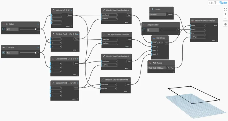
- The floor plan layout is given below:
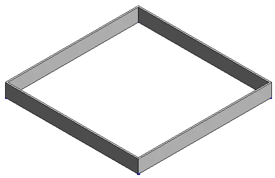
- Now, go to revit file to view the 3D form where the height of the wall is visible.
- The height of the wall can be adjusted using the slider.
- Now, we have to place the floor.
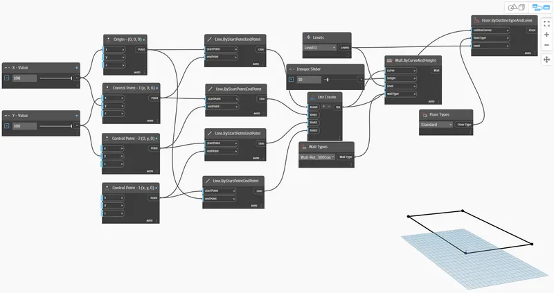
- For this, type floor in the library and select floor by outlinecurve, floor type and level.
- Select the type of the floor as standard floor.
- Connect all of the apporpriately shown in figure.
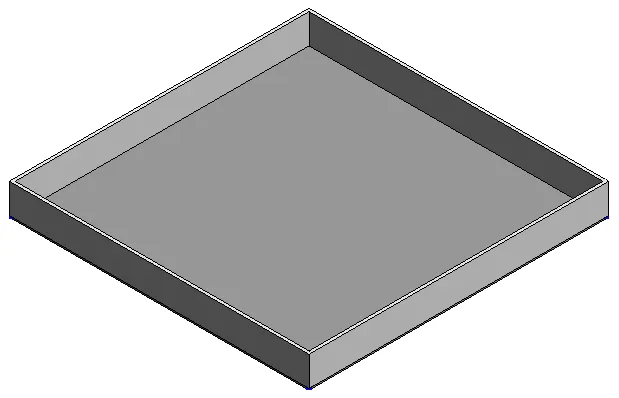
- This can be viewed in 3D view in revit file.
RESULT:-
Hence the conceptual floor plan layout has been created.
_____________________________________________________________________________________________________
3. Create an array of model elements in Revit. Use dynamo to vary the properties of model elements by using the slider or code block
AIM:- To create an array of model elements in Revit using dynamo to vary the properties of model elements by using the slider or code block.
INTRODUCTION:-
- The regular Rotate tool in Revit does not allow us to rotate multiple elements while each object is rotated around its own placement point but in the same direction as other objects.
- With this simple Dynamo Script you can select as many elements as you want and rotate them by their own axis in one click.
PROCEDURE:-
- Open the Revit software using the architectural template.
- Create columns of 24" X 24" .
- Open the dynamo tool, and then the dynamo will be opened.
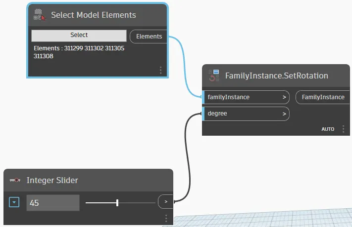
- In the library select model elements, integer slider and family instance.
- Create the integer the slider and give the value for the rotation.
- Connect elements of select model elements to the family instance of family instance.
- Connect integer slider to the degree of family instance.
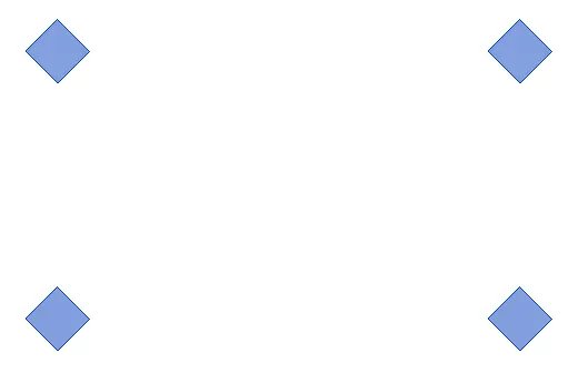
- Go back to revit screen the columns are rotated at 45 degrees.
RESULT:-
Created an array of model elements in revit using dynamo to vary the properties of model elements by using the slider or code block.
_____________________________________________________________________________
4. Create a conceptual mass in Revit and develop a parametric column by dividing the surfaces and apply the concepts similar to used in parametric walkway modelling. Use triangular bent or square shaped panels to add finish to the parametric column
AIM:- To create a conceptual mass in revit and develop a parametric column by dividing the surfaces and,To apply the concepts similar to used in parametric walkway modelling.
INTRODUCTION:-
- The conceptual mass allows you a bit more control with the added advantage that levels are visible in 3D. Here's what to do after opening the family: Select. draw tool (see in toolbar above) and draw on a work plane in plan view or elevation/3D view
- Masses are a particular category in Revit. It is independent from other categories from objects, and usually is a hidden category By default in views.
PROCEDURE:-
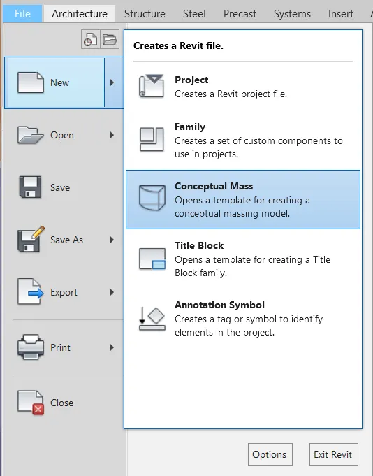
- Open the Revit software, and select the new option in the family/Conspectual mass.
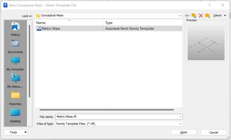
- Select the mass in the conceptual mass folder.
- Create a level at a height of 10' and rename it as height of the roof.
- Using the spline tool to draw the walkway curve in floor plan
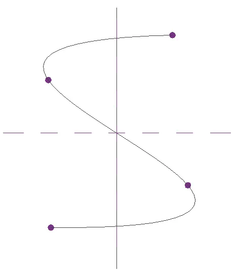
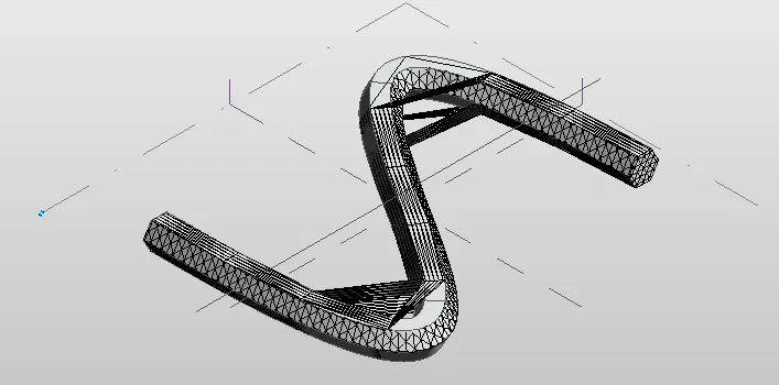
- The 3D view of floor plan.
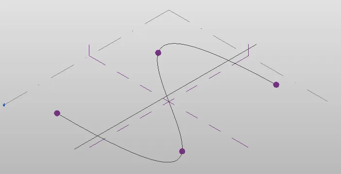
- Create the work place at the control points and draw the polygon with four sides to the workplace.
- Similarly create workplace at the control points and draw the polygon with four sides in different angles, as shown below.
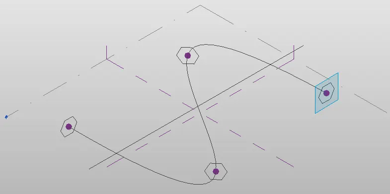
- Select the curve line, control points, work plane and polygon.
- And then create foam of it.
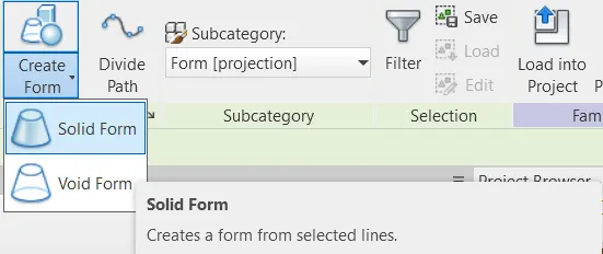
- The view after the solid form is created.
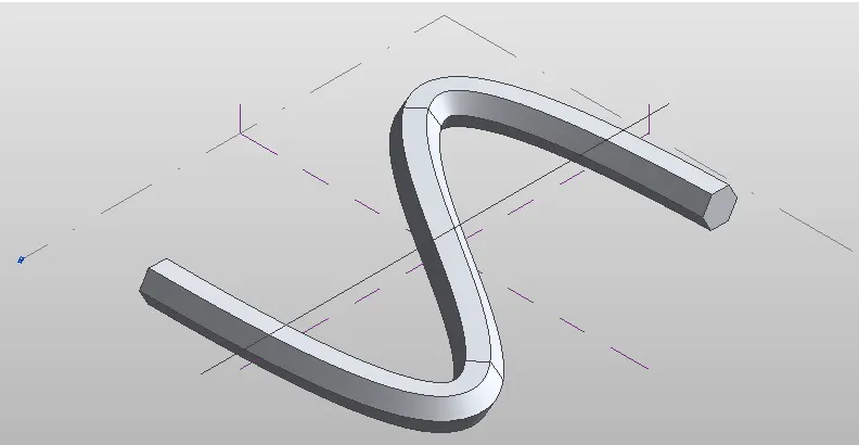
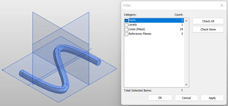
- Select the all the elements and filter it and select form and divide the form.
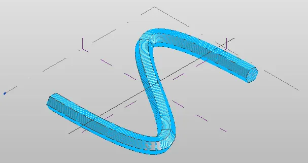
- After dividing select the divided surface and apply a triangle pattern.
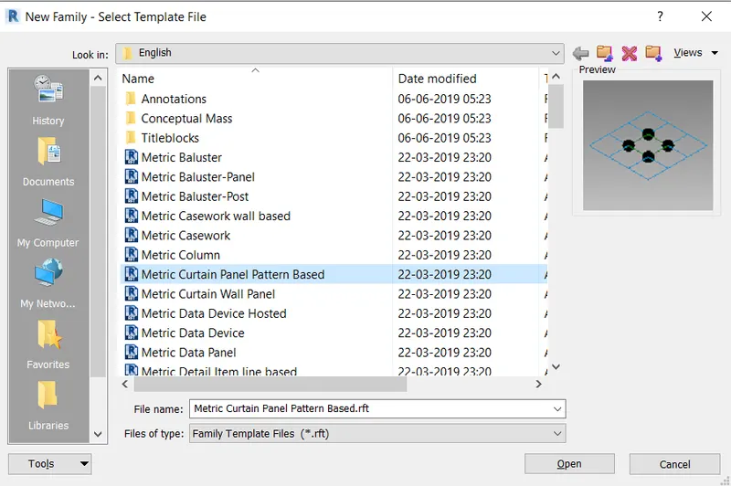
- Open the new family, and select the metric curtain panel pattern based.
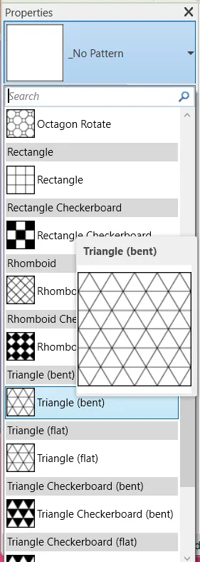
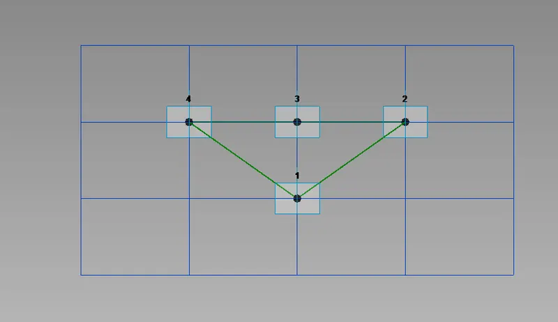
- Select the triangle bent pattern.
- Now, open a new family -->Curtain panel pattern based.
- Now, select the pattern as triangle bent.
- Then, create a reference point at centre of the face.
- Then draw a circle of radius 3" at that reference point.
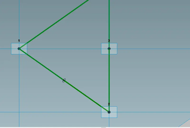
- Now, select the pattern, refrence plane and circle created and choose create form.
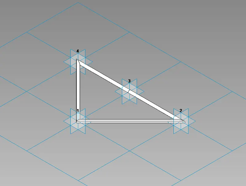
- Now, load this into the project.
- Now, select the enitre form of the walkway and filter it to retain only the divided surface.
- Then in the pattern select the family that we havee created just now.
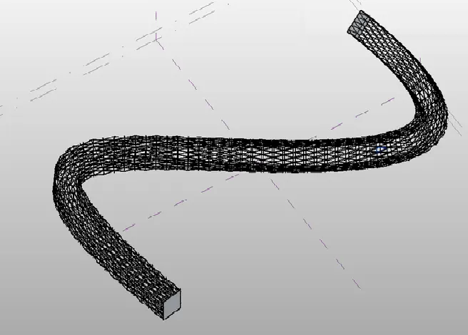
- Hence, the conceptual mass have been created.
RESULT:-
Created a conceptual mass in revit and developed a parametric column by dividing the surfaces and also applied the concepts similar to used in parametric walkway modelling.
__________________________________________________________________________________
5. Use Dynamo to work on developing a Parametric Stadium. List yur parameters and use the visual programming approach to complete the modelling, You can use the concepts discussed in parametric high rise tower in class for reference.
AIM:- To draw a parametric stadium using dynamo.
INTRODUCTION:-
- The conceptual mass allows you a bit more control with the added advantage that levels are visible in 3D. Here's what to do after opening the family: Select. draw tool (see in toolbar above) and draw on a work plane in plan view or elevation/3D view
- Masses are a particular category in Revit. It is independent from other categories from objects, and usually is a hidden category By default in views.
PROCEDURE:-
- Open the new file in Revit, and open the dynamo.
- In the library search slider and insert four sliders and rename them.
- Type code block and in that code block type (0..#levels..Floor Height)Next join levels and height
- In the library search Coordinate system by origin and join the code block to it in z.
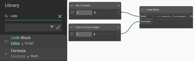
- In the library search rectangle by width and height and create two sliders for width and depth of the rectangle.
- Connect the co-ordinate system and two sliders to the rectangle by width and height.
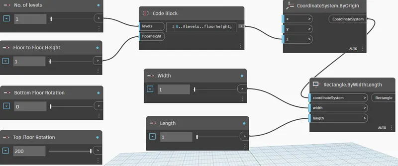
- Change the width to 10 and length to 10 in integer slider.
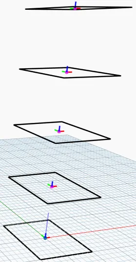
- Create code block and in that code block type (bottom..top..#levels)
- Join the bottom rotation and top rotation and number of levels to the above created code block.
- Create origin ,z- axis, geometry rorate and connect them as shown in fig.
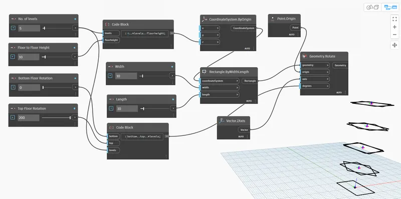
- Create surface by loft and connect geometry rotate to the surface by loft.
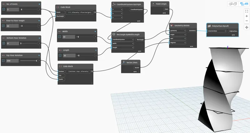
- The Actual view created is as follows
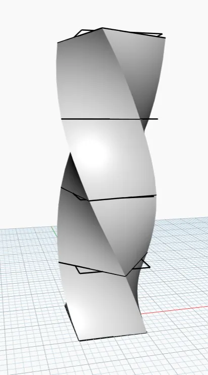
RESULT:-
The parametric stadium has been created successfully using dynamo.
_____________________________________________________________________________________________________