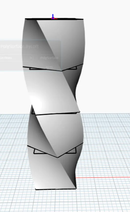
Creating Conceptual mass in REVIT and Creation of Sinusoidal curve and a Parametric stadium using Dynamo
1.Aim:
To create a set of sinusoidal points and create a curve and create a surface out of the curve using Dynamo.
Introduction:
Dynamo is a graphical programming interface that helps to customize the building information workflow. Dynamo is an open-source visual programming platform for designers. It is installed as part of Revit along with Revit specific programming nodes.
Procedure:
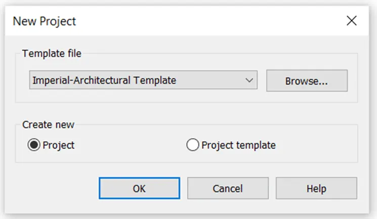
- Open a new file in Revit.
- Click manage tab to open Dynamo
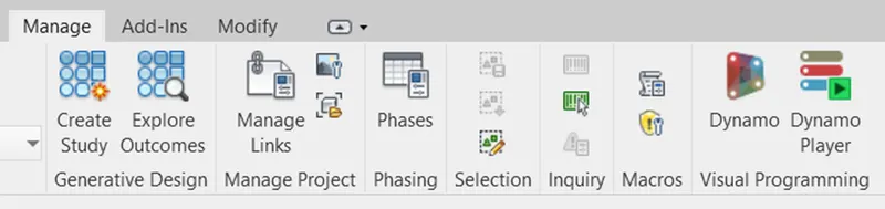
- Dynamo page will open after clicking the Dynamo icon
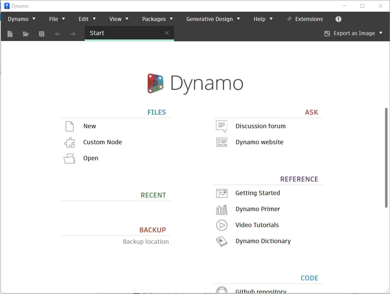
- Click new
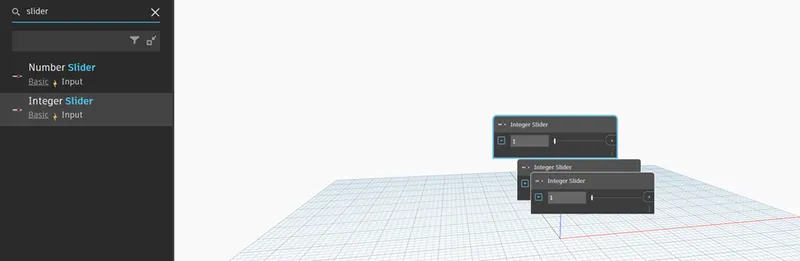
- Go to search and type slider and select the Integer slider 3 times.
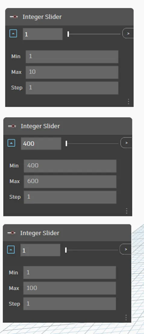
- Give the minimum, maximum and step value for each slider as follow.
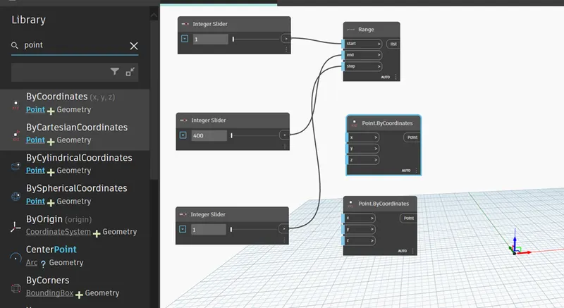
- From search, create a Range node for connecting the sliders and 2 Point. By Coordinates for form 2 sinusoidal curves
- Search and create code block and Math.sin
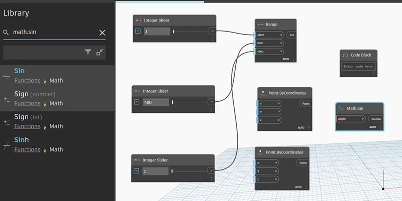
- Wire the list in range to the 2-point nodes and angle in math. Sin nodes.
- Create a product node from search.
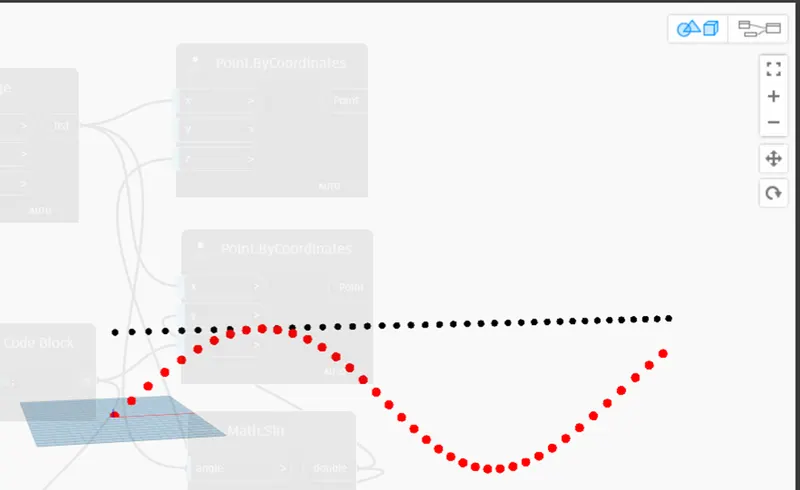
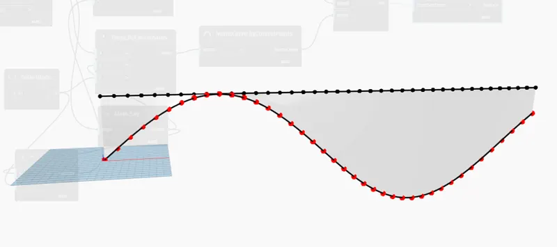
- Wire the nodes to get 2 sinusoidal curves.
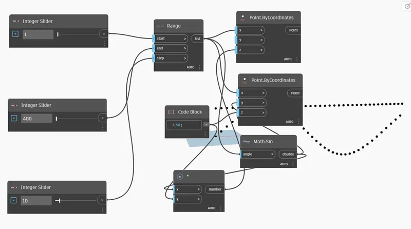
- Sinusoidal curves in 3D view
- Create 2 NurbsCurve.By control points nodes and wire it with the points.By coordinates to create the spline curve using control points.
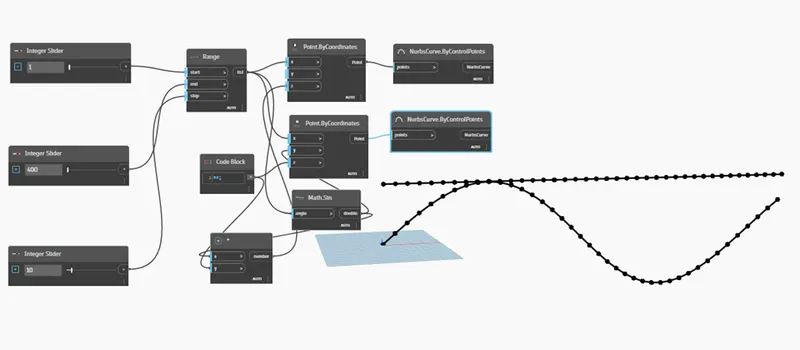
- Create the List Create node and connect it with the NurbsCurve.By control points.
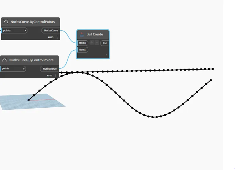
- Create surface.By Loft node to create a surface by lofting two input
Curves.
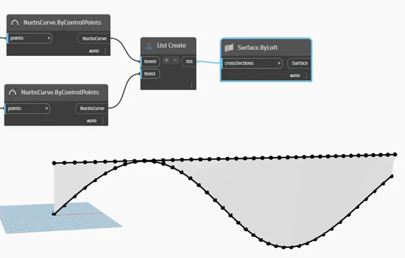
Result:
Hence the result is obtained by following above steps.
2.Aim:
To create a conceptual layout of floor plan in dynamo and to link the lines to appropriate model elements in Revit by choosing the wall types and wall parameters.
Introduction:
Dynamo is a graphical programming interface that helps to customize the building information workflow. Dynamo is an open-source visual programming platform for designers. It is installed as part of Revit along with Revit specific programming nodes.
Procedure:
- Open a new Dynamo file
- Create 2 Integer slide and 4 Points.By Coordinates to create wall
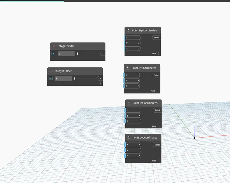
- Name the nodes and wire the as shown below
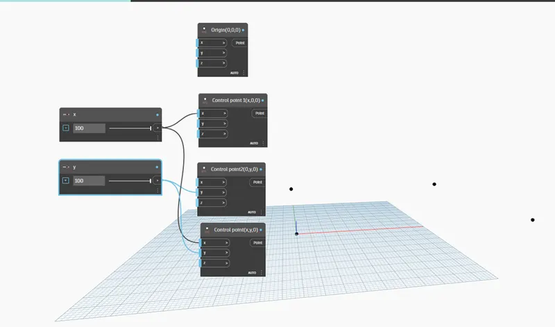
- In search enter Line.ByStartPointEndPoint and click 4- times
- Join the using wire by joining the axis points as shown below
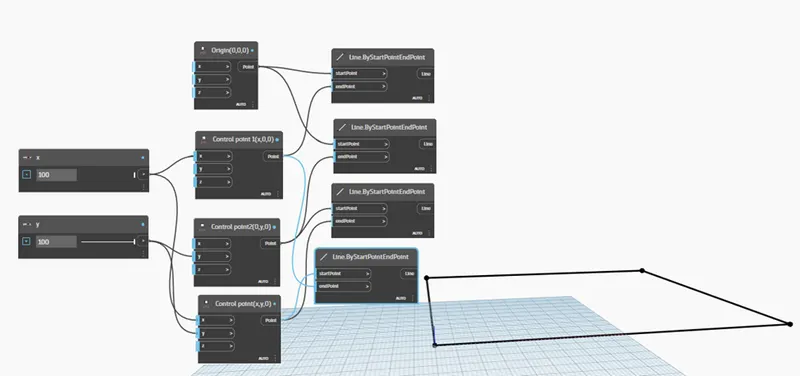
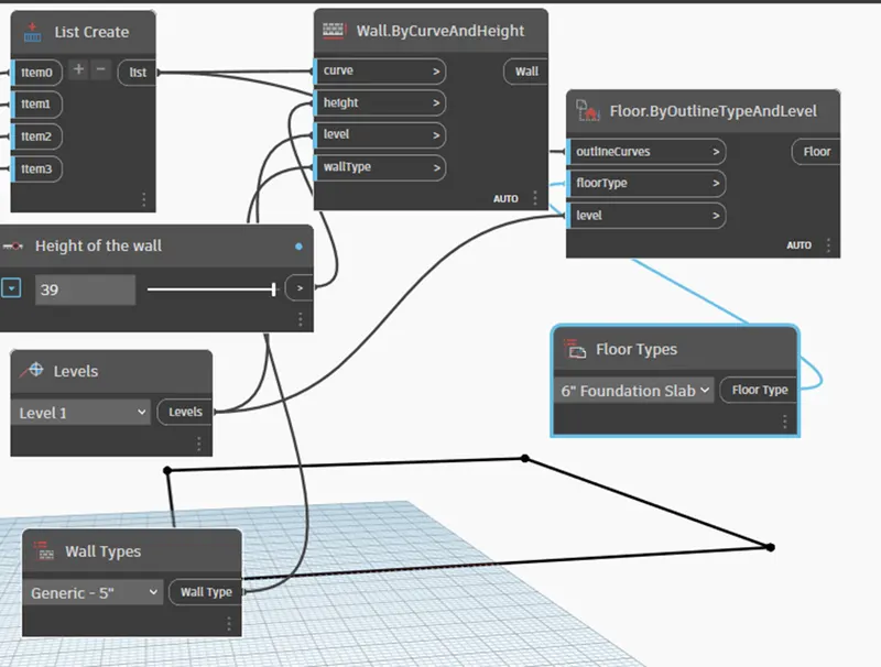
- To create wall, enter Wall.BycurveAndHeight and wall type
- Select the wall type as Generic 5”, Level as 1, height of the wall and list.
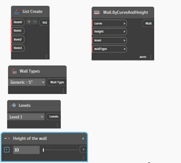
- Wire the parameters as shown below
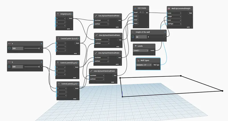
- The wall is created in the Revit
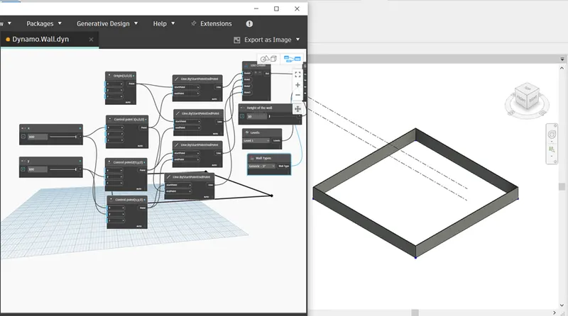
- Enter Floor type and Floor.ByOutline TypeAndLevel and wire the them to respective parameter which created earlier as shown below.
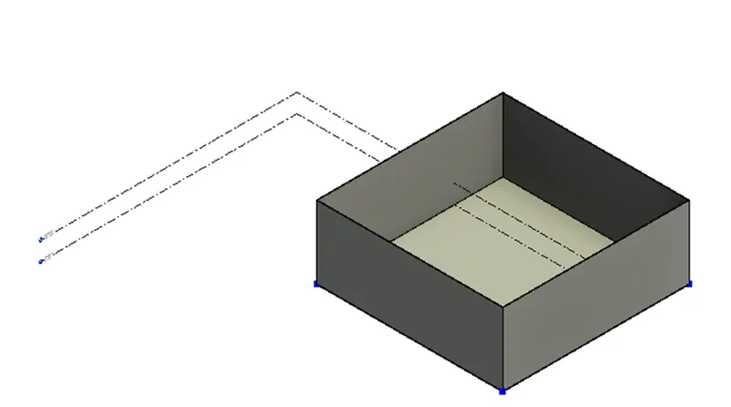
- Result:
- Variation in height of the wall:
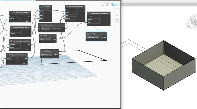
- Variation in length of the wall:
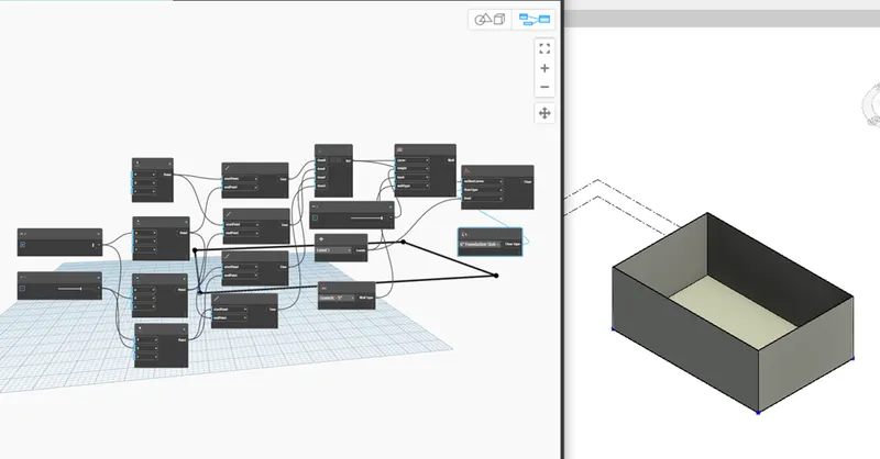
- Hence the result is obtained.
3.Aim:
To create an array of model elements in Revit and by using dynamo to vary the properties of model elements.
Introduction:
Dynamo is a graphical programming interface that helps to customize the building information workflow. Dynamo is an open-source visual programming platform for designers. It is installed as part of Revit along with Revit specific programming nodes.
Procedure:
- Open the new Revit file
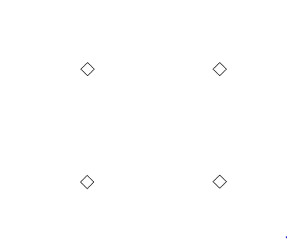
- Place 4 architectural columns as shown below
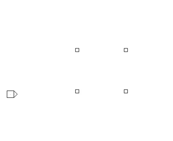
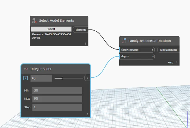
- In Dynamo, enter select model elements to select the columns. Create Family Instance.SetRotation for rotating the column. Select Integer Slider to give the angle.
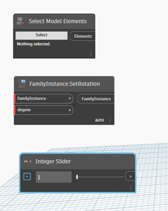
- Click select in the select model elements and go to Revit page and select all the 4 columns and come back to Dynamo screen
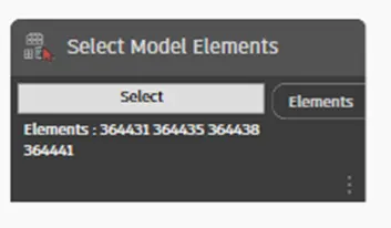
- Wire all the nodes respectively
Results:
- Hence the result is obtained by following above steps.
4.Aim:
To Create a conceptual mass in Revit and develop a parametric column by dividing the surfaces and apply the concepts similar in parametric walkway modelling. And to use triangular bent or square shaped panels to add finish to the parametric column.
Introduction:
Dynamo is a graphical programming interface that helps to customize the building information workflow. Dynamo is an open-source visual programming platform for designers. It is installed as part of Revit along with Revit specific programming nodes.
Procedure:
- In Revit, Go to fileànewàconceptual mass
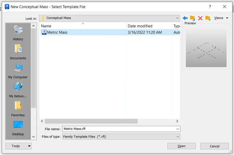
- Once the file is open go to elevation view and level 2 of 12’
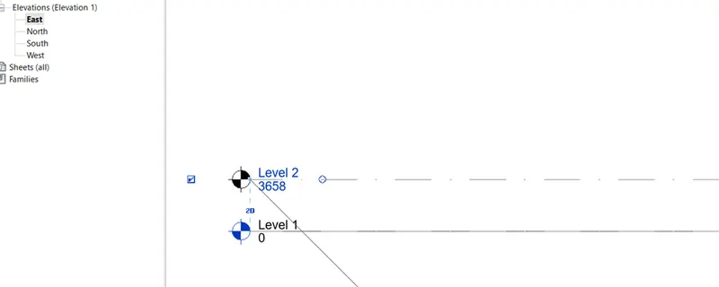
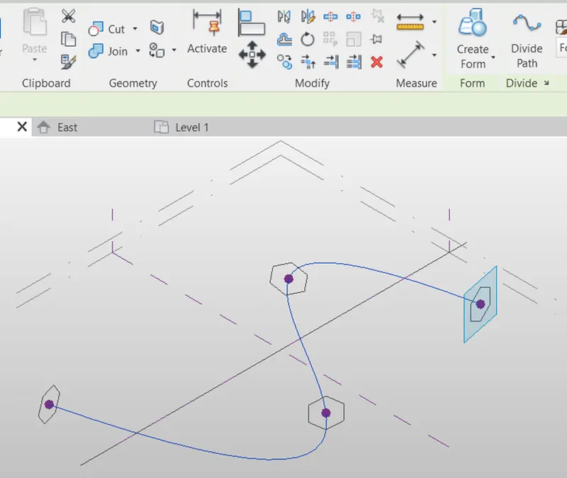
- Go to create tab and select model line and select spline through points
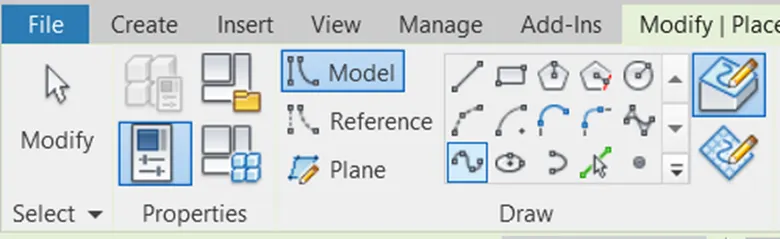
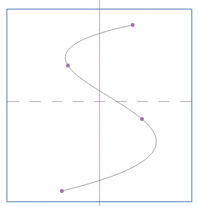
- Draw the spline curve as shown below.
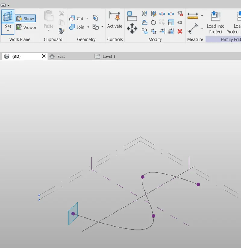
- Go to 3D View and select set work plane icon and place it on spline points.
- On every set work plane place the circumscribed polygon as shown below.
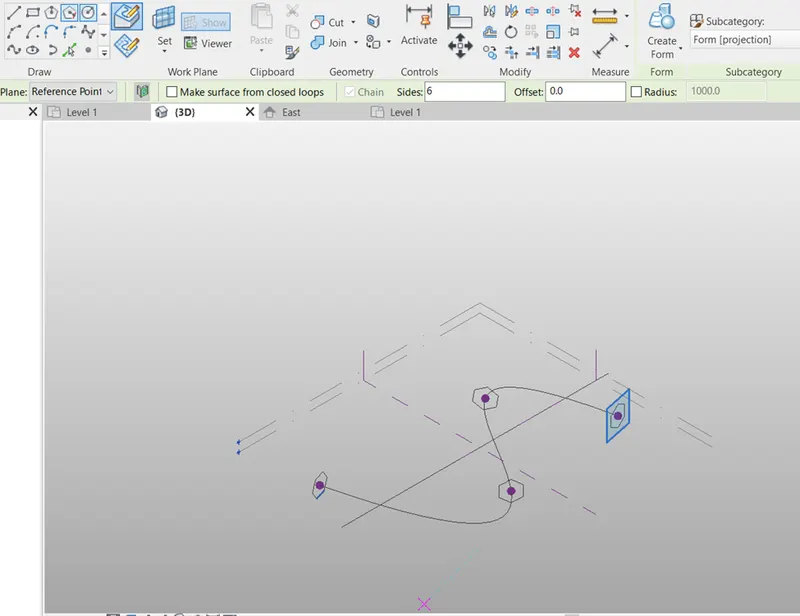
- Click the curve, create form icon will appear on the panel.
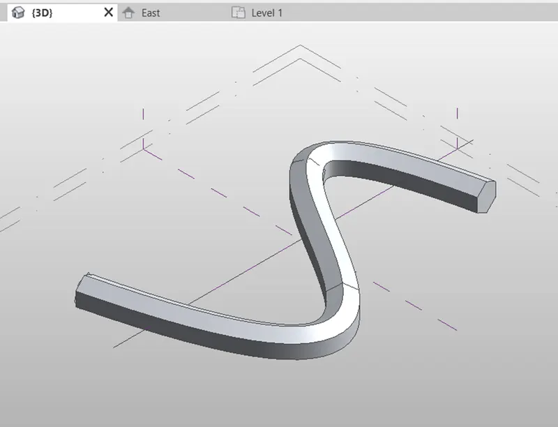
- Press control and select the plane and click the solid form from create form drop down.
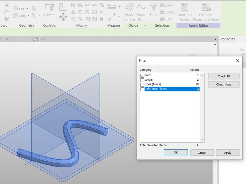
- Select all and filter and select only the form option and click ok.
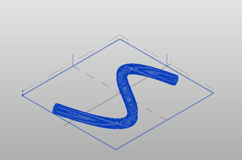
- Select Divide surface icon in the panel.
- Change no pattern to triangular bent in properties browser.
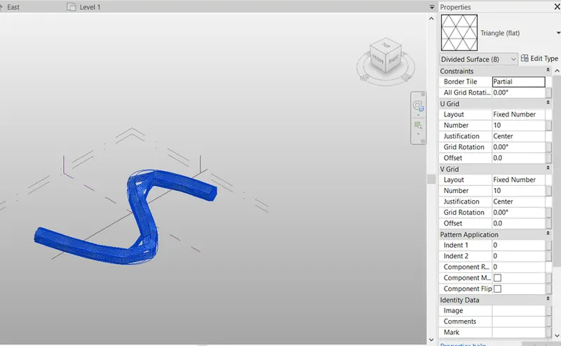
- To get the smooth curve go to properties browser and change the U grid and V grid numbers as follow.
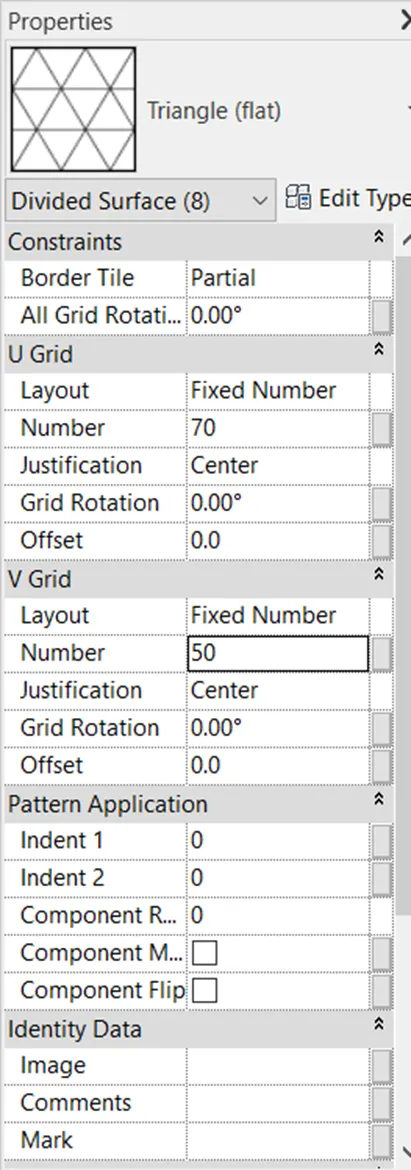
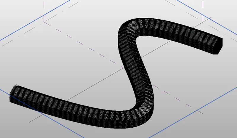
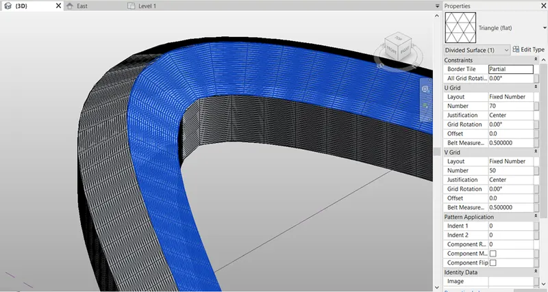
Results:
- Hence the result is obtained by following above steps.
5.Aim:
To use Dynamo to work on developing a Parametric Stadium.
Introduction:
Dynamo is a graphical programming interface that helps to customize the building information workflow. Dynamo is an open-source visual programming platform for designers. It is installed as part of Revit along with Revit specific programming nodes.
Procedure:
- Open new Dynamo page
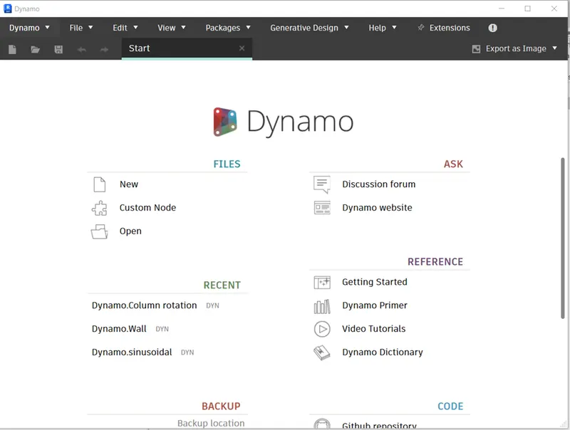
- Click new.
- Create 2 integer slider and code blocks.
- Rename it and enter the value and codes.
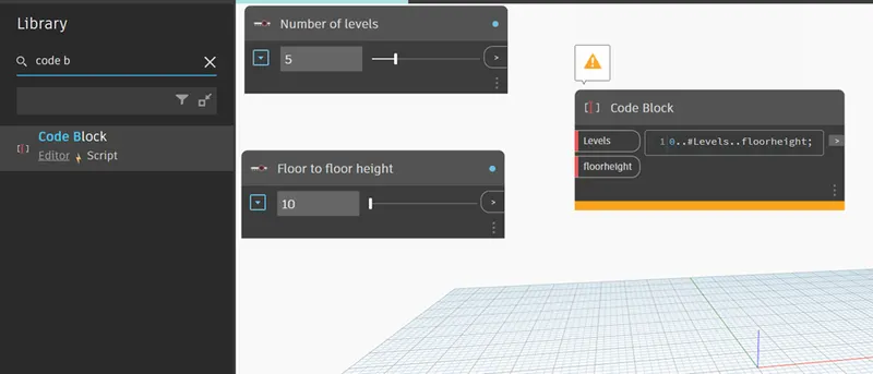
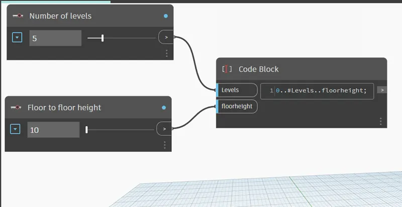
- Connect it to the respective parameters
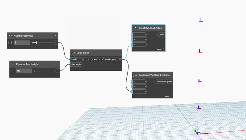
- Create point.ByCoordinates and CoordinateSystem.ByOrigin nodes.
- Connect Z from both nodes to the code block.
- Create 4 more integer slider for length, width and rotation of the building.
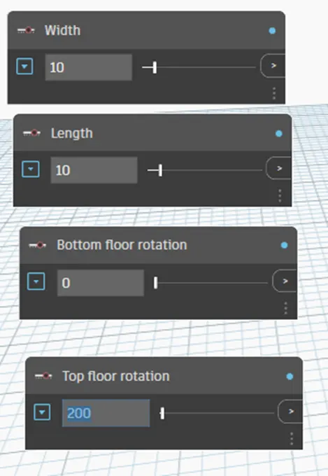
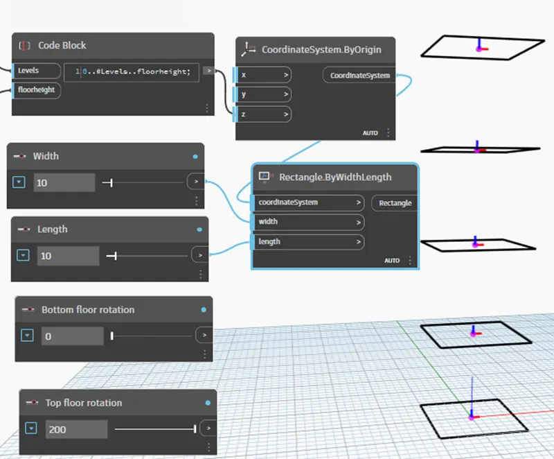
- Create coordinateSystem.ByOrigin and rectangle nodes
- Wire it accordingly
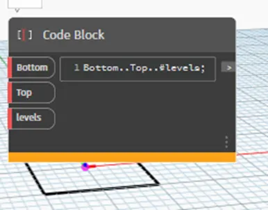
- Create a code block for rotation
- Wire it to its parameters
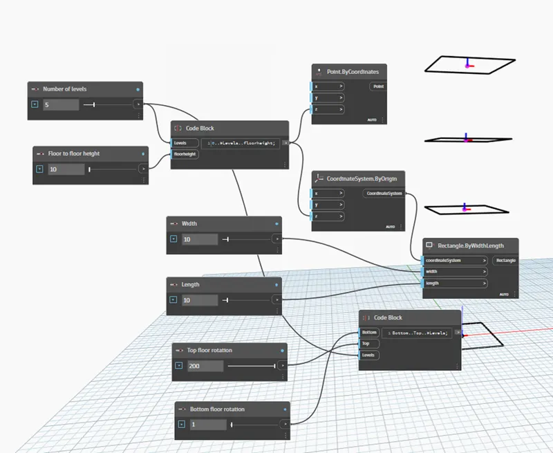
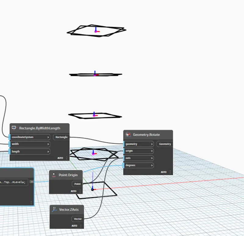
- Create Point.origin, vector Z, Geometry.rotate nodes
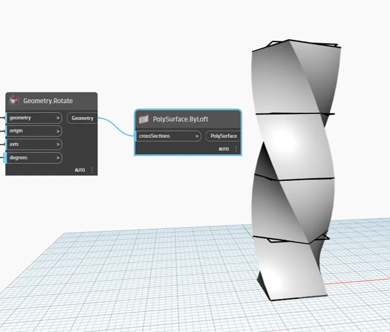
- Create polysurface.ByLoft
- Connect it to Geometry.Rotate
Result:
- Hence the result is obtained.