Creating Conceptual mass in REVIT and Creation of Sinusoidal curve and a Parametric stadium using Dynamo
INTRODUCTION TO DYNAMO :
- Dynamo is a graphical programming interface that lets you customize your building information workflow.
- Dynamo is an open source visual programming platform for designers. It is installed as part of Revit
- Dynamo is a visual programming tool that works with Revit. Dynamo extends the power of Revit by providing access to the Revit API (Application Programming Interface) in a more accessible manner. Rather than typing code, with Dynamo you create programs by manipulating graphic elements called “nodes”. It’s an approach to programming better suited for visually oriented types, like architects, designers, and engineer.
- In Dynamo, each node performs a specific task. Nodes have inputs and outputs. The outputs from one node are connected to inputs on another using “wires”. The program or “graph” flows from node to node through the network of wires. The result is a graphic representation of the steps required to achieve the end design.
BENEFITS OF USING DYNAMO -
- Automate repetitive tasks.
- Access your building data.
- Explore multiple design options.
- Test Performance.
- Think Computationally.
1. Using Dynamo create a set of sinusoidal points and create a curve and create a surface out of the curve.
ANS.
- CREATION OF CURVE -
- Open Revit with Architectural template.
- To access Dynamo, click Manage tab Visual Programming panel Dynamo.
- Create 3 blocks of Point by coordinates.
- Rename the blocks as Origin point, Middle point, End point respectively.
- Create a Code block, give the parameter 50.
- Join the code block t the previously prepared points to x.
- Create number sliders and join to the code block.
- Create the list create block and add 2 no’s of list.
- Join the blocks of Original, Middle and End point to Item0, Item1 of the list create block.
- Create blocks of curve plane parameter and Math. Range.
- Create code block and give the parameter and join the code block to curve plane parameter.
- Create Nurbs curve and connect to the list create.
- Create the block of surface by Loft and connect the block.
- In this way the curve with surface is formed using dynamo.
SINUSOIDAL POINTS CREATED
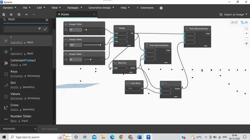
- SINUSOIDAL POINTS
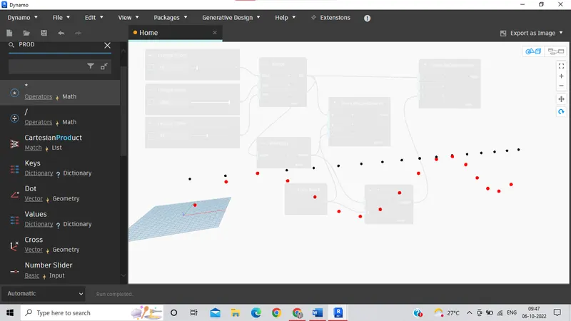
- SINUSOIDAL POINTS AND CURVES CREATED
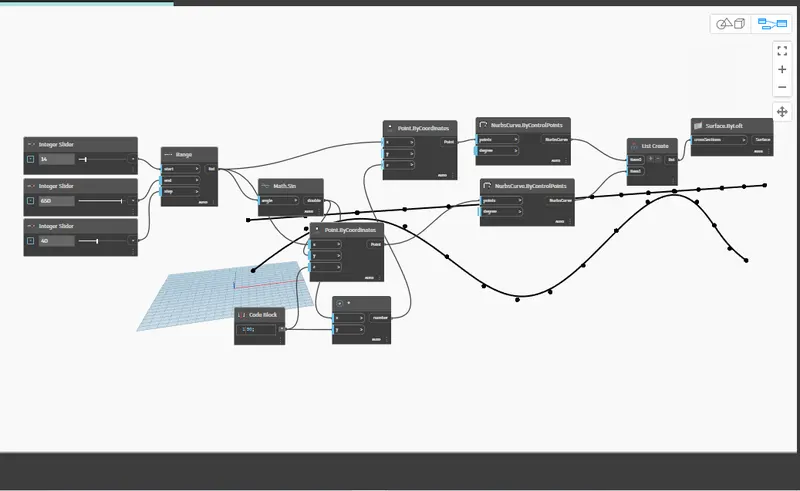
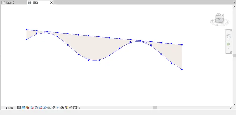
- CURVE OPENED IN REVIT WINDOW
--------------------------------------------------------------------------------------------------------------------------------
2. Create a conceptual layout of floor plan in dynamo
ANS.
- CREATION OF LAYOUT IN DYNAMO -
- Open Revit with Architectural template.
- To access Dynamo, click Manage tab Visual Programming panel Dynamo.
- Select four integer sliders and create four points.
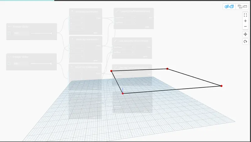
- lines were created from those points
- list option is lected to give wall parameters
- Then the wall parameters were added sch as level, height of wall, wall type.
- this points were connected and the wall is created
- FIRST THE FOUR POINTS WERE CREATED
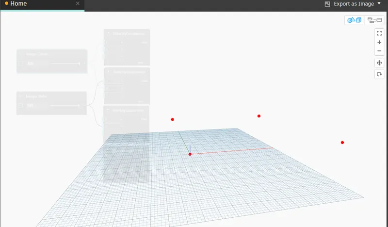
- DYNAMO PATTERN FOR FOUR LINES OF WALL
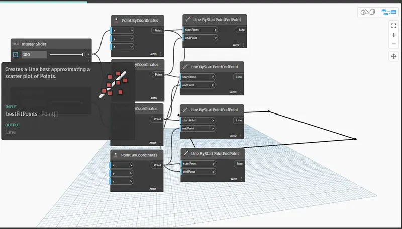
- FOUR LINES OF WALL LAYOUT CREATED IN DYNAMO
- DYNAMO WALL STRUCTURE PATTERN
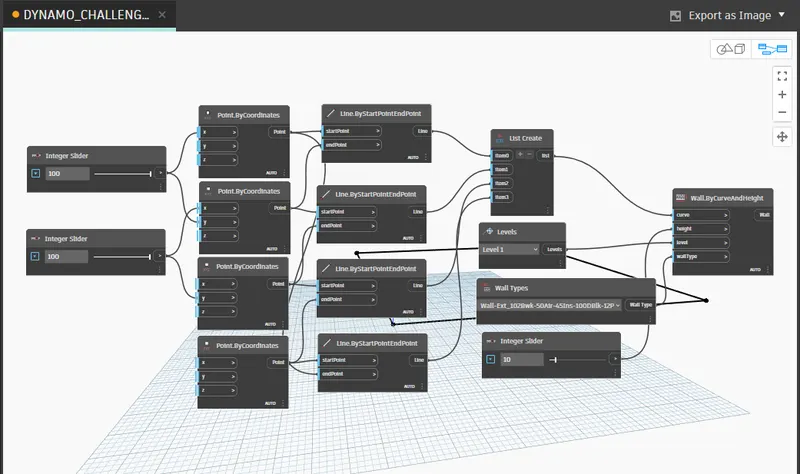
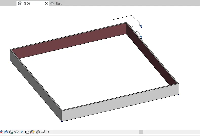
- WALL CREATED IN DYNAMO AND VIEW IN REVIT
--------------------------------------------------------------------------------------------------------------------------------
3. Create an array of model elements in Revit. Use dynamo to vary the properties of model elements by using the slider or code block.
ANS.
- CREATION OF MODEL -
- Open Revit with Architectural template.
- Change to units to feet and inches using Un command in Revit.
- Set the levels as level 0 to 0’ and level 1 to 10’.
- Draw column in the Revit.
- Copy the column at an offset of 7’ .
- Draw such 4 nos of column.
- Now access Dynamo, click Manage tab Visual Programming panel Dynamo.
- No create the block of Select model elements and select the 4 drawn columns in Revit.
- The Coordinates of the 4 columns will be appearing on the Select model elements tab.
- Create the number slider with minimum of 10 maximum of 100 at a stage of 1.
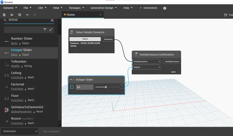
- Now create the family instance set rotation.
- Connect the block of select model elements to family instance.
- And finally connect the number slider to the degree option in family instance block.
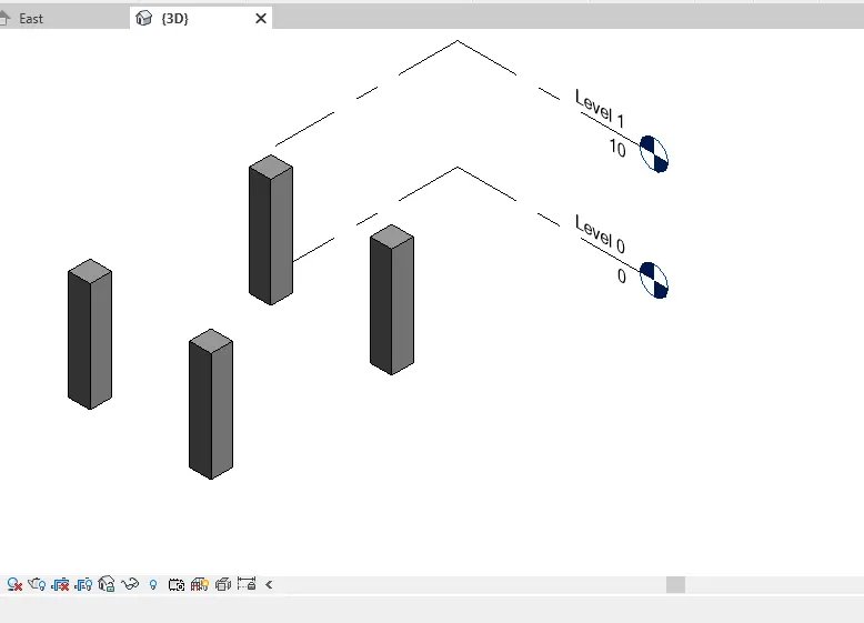
- COLUMNS WERE CREATED IN REVIT
- DYNAMO PATTERN TO ROTATE COLUMN
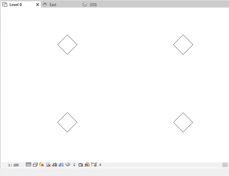
- AFTER GIVING VALUE IN INTERGER SLIDE IN DYNAMO, THE COLUMNS ARE ROTATED IN REVIT AS WE CAN SEE IN IMAGE BELOW
--------------------------------------------------------------------------------------------------------------------------------
4. Create a conceptual mass in Revit and develop a parametric column by dividing the surfaces and apply the concepts similar to used in parametric walkway modelling. Use triangular bent or square shaped panels to add finish to the parametric column.
ANS.
- CREATION OF CONCEPTUAL MASS DEVELOPING IT -
- Open Revit 2021, open families and select new tab.
- A dialog box will be appearing on the screen showing 3 different files that are Annotations, conceptual mass and title blocks, select conceptual mass and select mass.
- A new family will be opened in the revit of the conceptual mass.
- Change the units to feet and inches using the UN command.
- Go to the elevation view and create level at 10’ from previously created level.
- A level 2 will be formed, rename the level 2 as Height of the Roof.
- Go to the levels in the property browser and select Height of roof level.
- Now go to the modify tab and set the work plane to the level of Height of Roof.
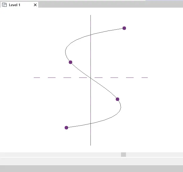
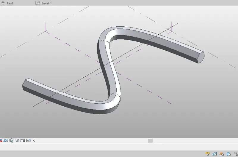
- Create the spline curve that is the S shaped curve in the working area of the Revit.
- Adjust the control points as needed and move them to adjust the curve.
- Go to the 3D view and the spline curve will be created.
- Now we have to create the profile to sweep.
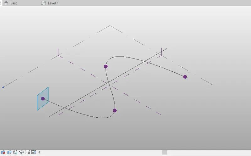
- Select the control point and set the plane and select show plane.
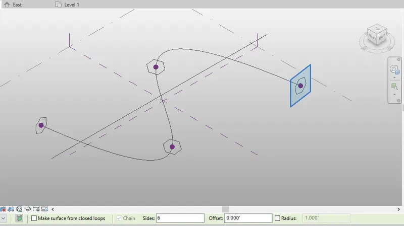
- Now create the polygon of 4 sides and draw in the work plane created.
- Do the same process for all the control points.
- Now select the curve and select all the polygons which has been drawn previously and select form tab and, in the tab, select create form.
- An automatic form will be created on the path of the curve.
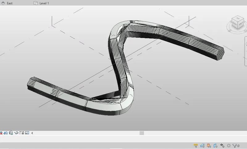
- Select the curve and divide the curve into various parts and select the pattern of the curve.
- Now go to the file and create new family and select the family as Curtain panel pattern based and select Ok.
- Select the triangle bent pattern.
- Create the work plane by selecting the midpoint and draw the circle and sweep the circle.
- Now click on the tab of load into family.
- The walkway will be created.
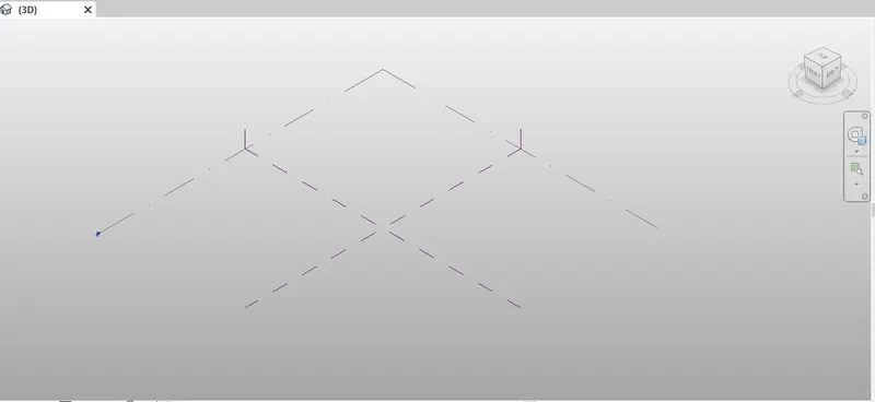
- OPEN THE CONCEPTUAL MASS TEMPLATE
- CREATE SPLINE FROM MODEL LINE
- SET PLANE AT EVERY POINT
- CREATE HEXAGON AT EVERY PLANE OF 10'
- CREATED SOLID FORM OF SPLINE
- TRIANGLE BENT PATTERN WAS GIVEN TO SOLID MASS FORM
--------------------------------------------------------------------------------------------------------------------------------
5. Use Dynamo to work on developing a Parametric Stadium.
ANS.
- CREATION OF PARAMETRIC BUILDING -
- Open Revit with Architectural template.
- To access Dynamo, click Manage tab Visual Programming panel Dynamo.
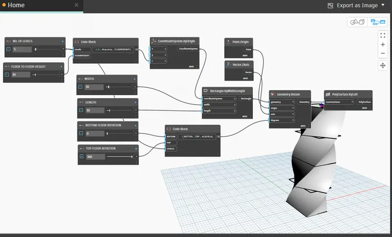
- Create 4 number of sliders, rename it as Number of Levels, Floor to Floor height, Bottom Floor Rotation, Top Floor Rotation.
- Now create the code block and enter 0..#Levels..FloorHeight; in the code block.
- Join the block of Number of levels and Floor to Floor height to the Code block as shown in the image.
- Create a block of Coordinate systems by origin and connct the code block to it.
- Create block of RectangleByWidthLength and connect block of Coordinate system by origin to the block as shown in the image.
- Create another code block and enter the code as Bottom..Top..#Levels; and connect to the slider of Bottom floor rotation and Top Floor rotation.
- Create another slider and set the limits and rename it as Width/Length of rectangle.
- Connect the slider to the previously created block of Rectangle by widthlength.
- Create another block of Geometry.Rotate.
- Create bocks of Point.Origin and Vectorzaxis and connect it to the bloc of Geometry Rotate.
- And finally create the block of PolySurface.ByLoft and cnnect it to the Feometry.Rotate block.
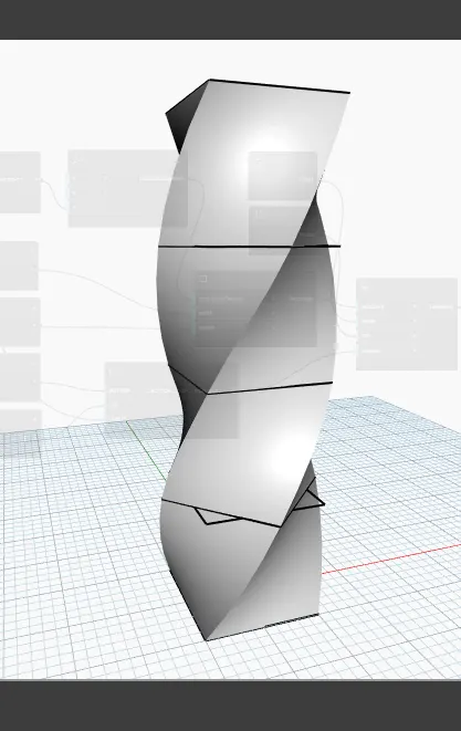
- The parametric building will be created.
- CODE FOR PARAMETRIC STADIUM
- PRAMETRIC STADIUM IN DYNAMO
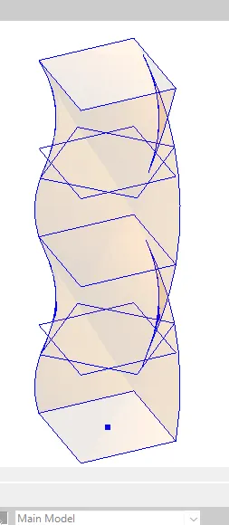
- PARAMETRIC STADIUM IN REVIT
--------------------------------------------------------------------------------------------------------------------------------