Creating Conceptual mass in REVIT and Creation of Sinusoidal curve and a Parametric stadium using Dynamo
1) Using Dynamo create a set of sinusoidal points and create a curve and create a surface out of the curve.
INTRODUCTION:
Dynamo is, quite literally, what you make it. Working with Dynamo may include using the application, either in connection with other Autodesk software or not, engaging a Visual Programming process, or participating in a broad community of users and contributors.
AIM:
To create a set of sinusoidal points and create a curve and create a surface out of the curve using Dynamo .
COMMANDS ARE USED:
- Manage
- Dynamo
- Integer slider
- Code block
- Point by co ordinates
- Rotate
- Surface by loft
- List create
- Range
- Nurbs curve
- Mathsin
PROCEDURE:
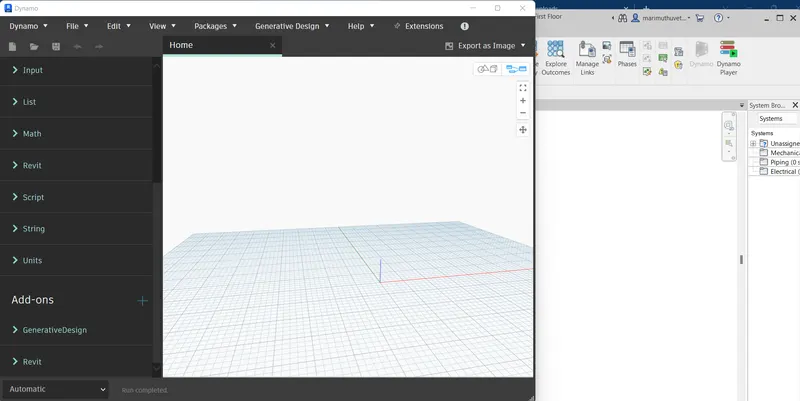
- To Open the revit software and click architectural template go for manage tab click on dynamo .
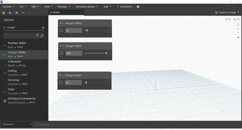
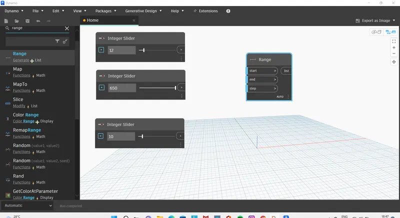
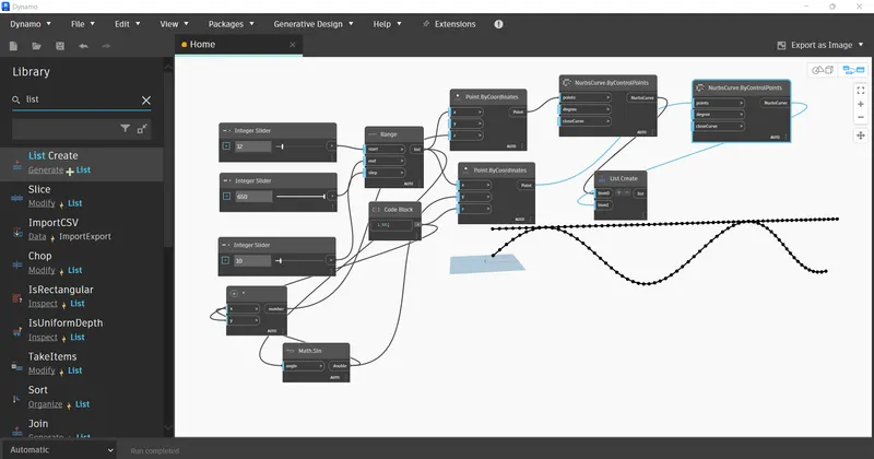
- Next add an integrer slider 3 nos and add the range
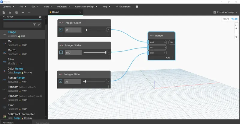
- Next To connect integer slider (numbers and steps ) to range to coordinates (x axsis)
- Next we connect to an point by co ordinates
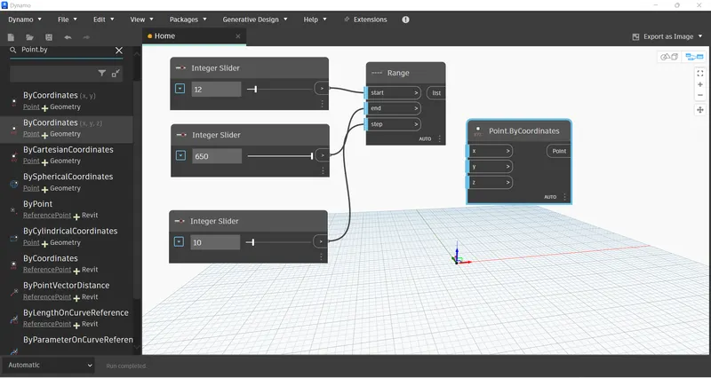
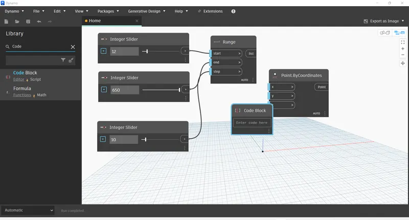
Simatenously add code block
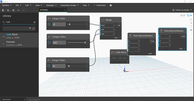
Add another point by co ordinates
- Connect the range to the point co ordinates
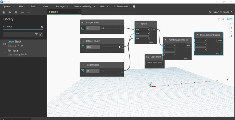
To be add an math sin simatenoulsy to take the a value at the code block 50
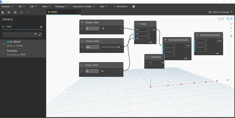
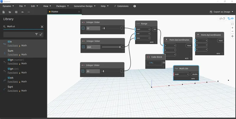
To connect to the range to the point co ordinate and math sin
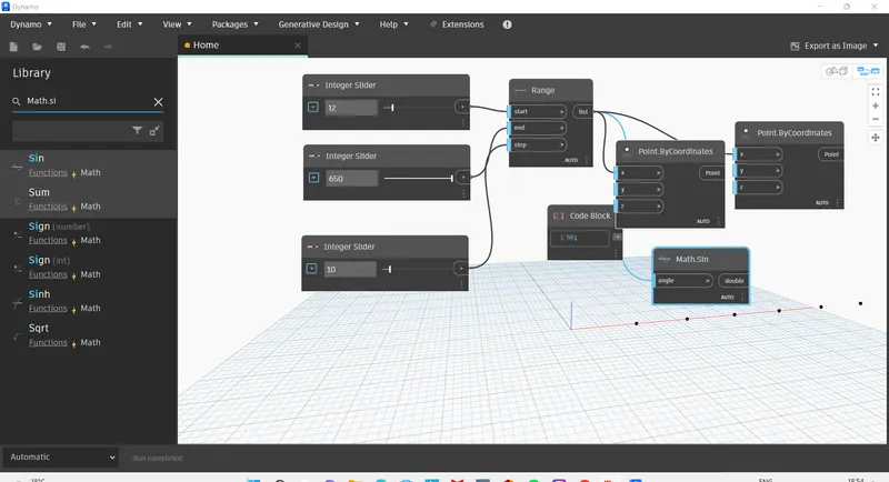
To connect the code block to the co ordinates
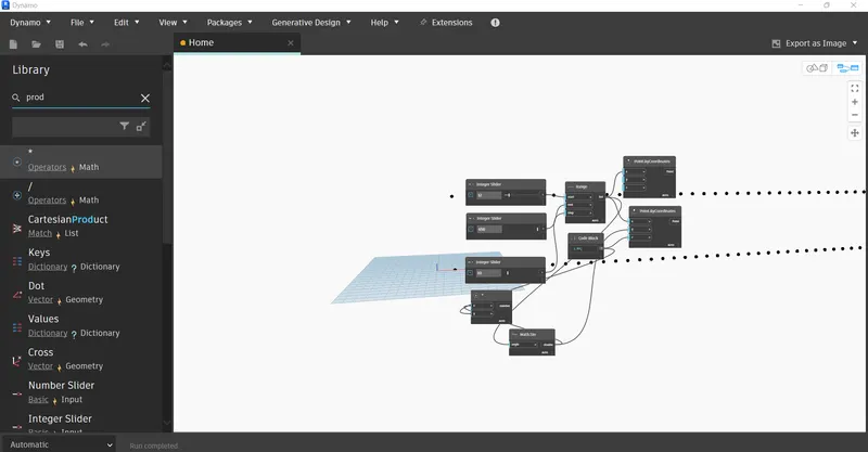
Once check the curve of the diagaram
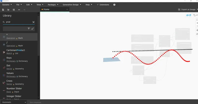
To craete the nurbs by curve at they create the line at the point
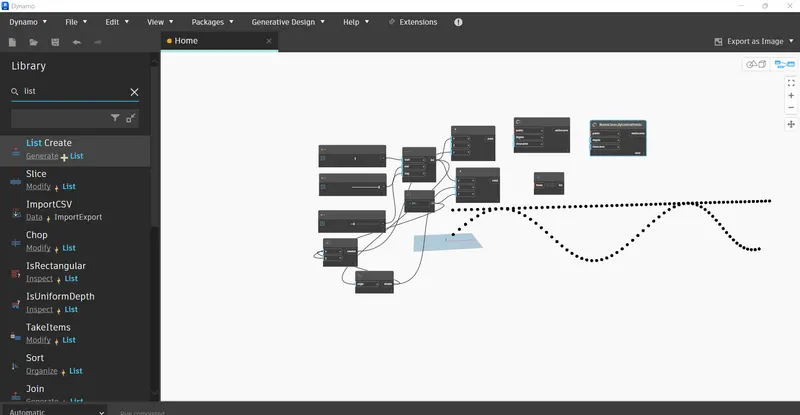
To be create the list create option and choose connect to the points by co ordinate
To add the surface of the loft to type the surface loft and placed it
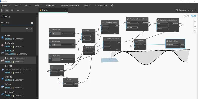
After that once check the diagram
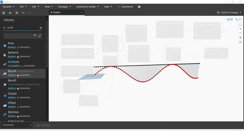
RESULT:
Finally we draw te curve and place the surface loft of the curve
2) Create a conceptual layout of floor plan in dynamo . Using the tools available in dynamo link the lines to appropriate model elements in Revit by choosing the wall types and wall parameters. Make use of the sliders to slide through the height of the wall and length of the wall.
AIM:
To Create a conceptual layout of floor plan in dynamo.
COMMANDS ARE USED:
- Manage
- Dynamo
- Integer slider
- Code block
- Point by co ordinates
- Rotate
- Surface by loft
- List create
- Range
- Nurbs curve
- Mathsin
PROCEDURE:
- To Open the revit software and click architectural template go for manage tab click on dynamo .
- Next add an integrer slider
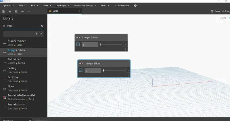
To be add an point by co ordinates
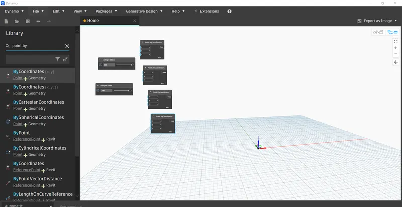
And next go for an line by start points to end point are choose
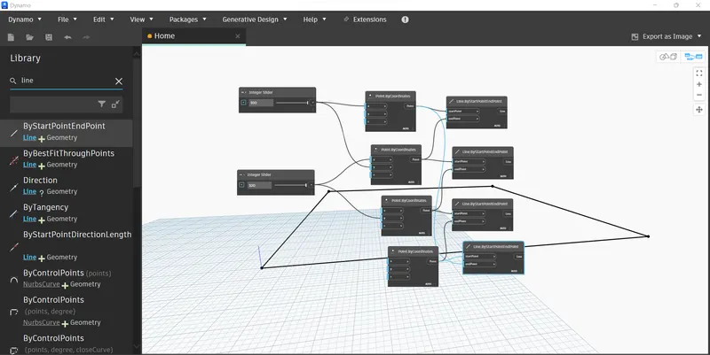
Once will checked the layout
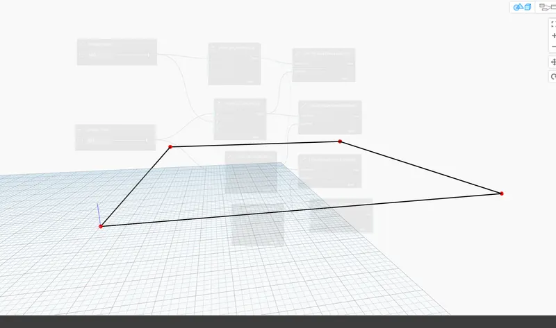
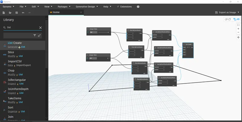
To create an list create add item 3 and to connect the list create to the point by start point to end point
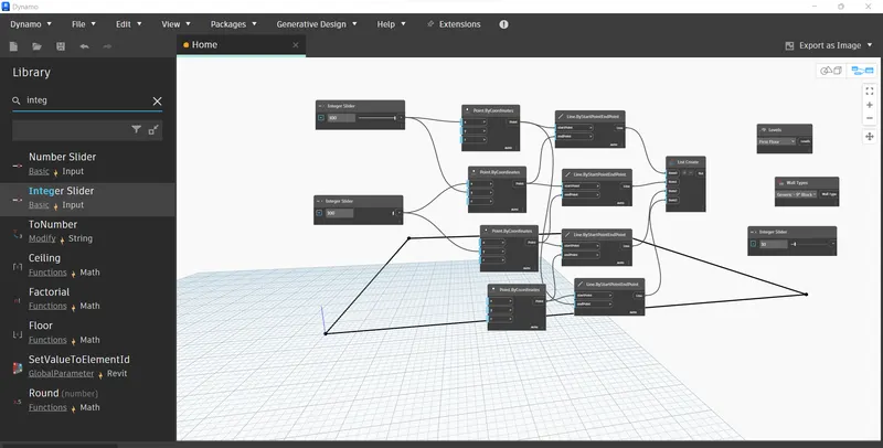
And next go for an walls , levels and integer slider
To choose the floor by out line and the wall by curve and height
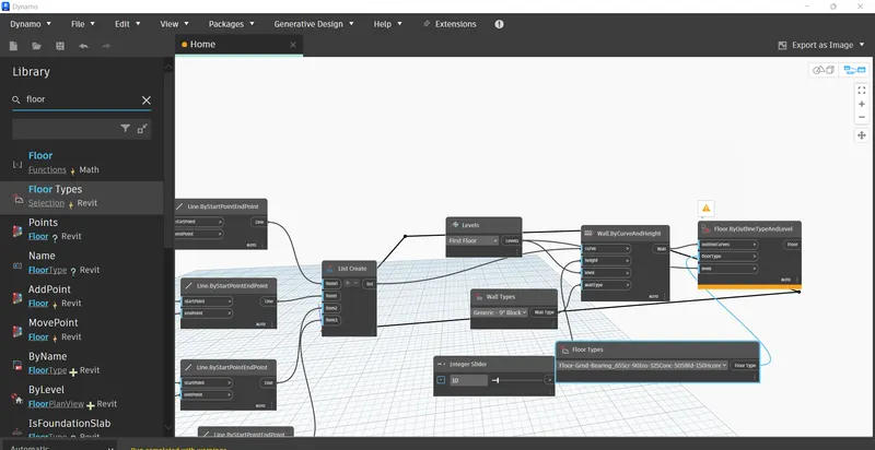
RESULT:
Finaly we draw the wall type and parameters
3) Create an array of model elements in Revit. Use dynamo to vary the properties of model elements by using the slider or code block
AIM:
To Use dynamo to vary the properties of model elements by using the slider or code block
COMMANDS ARE USED:
- Manage
- Dynamo
- Integer slider
- Code block
- Point by co ordinates
- Rotate
- Surface by loft
- List create
- Range
- Nurbs curve
- Mathsin
PROCEDURE:
- First go for an revit software and go for construction template
- And go for an architecture column and choose column
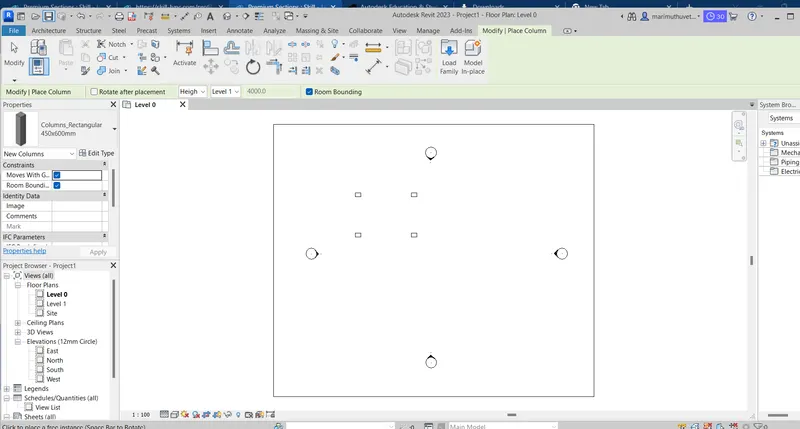
- To create an model elements and go for an revit and choose column
- Next go for family instance rotation
- To add an elements to the family instance
- We mentioned the degree of sliding so took integrer slider
- measurement of 45 degree sliding
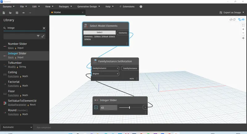
After that once check the revit software the column as rotated
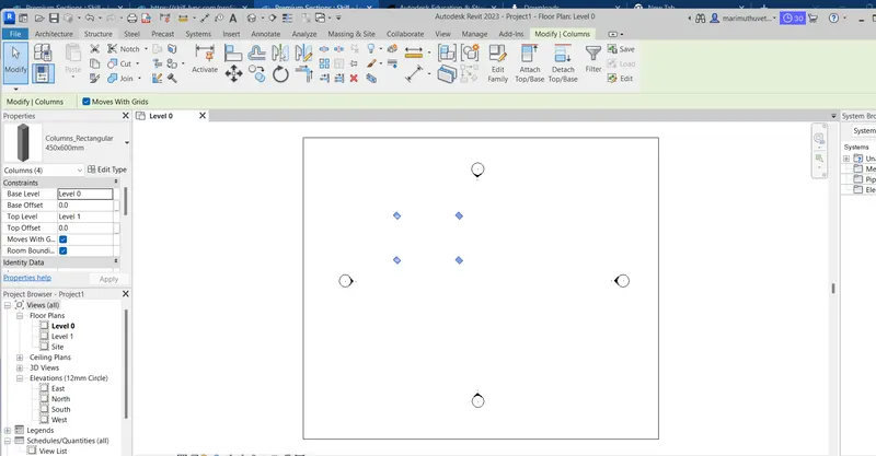
RESULT:
Finally we create an array at the dynamo
4) Create a conceptual mass in Revit and develop a parametric column by dividing the surfaces and apply the concepts similar to used in parametric walkway modelling. Use triangular bent or square shaped panels to add finish to the parametric column
AIM:
To create a set of sinusoidal points and create a curve and create a surface out of the curve using Dynamo .
COMMANDS ARE USED:
- Architectural
- Level
- Model
- Set
PROCEDURE:
- To open the revit software and open conceptual mass
- Open for an metric mass
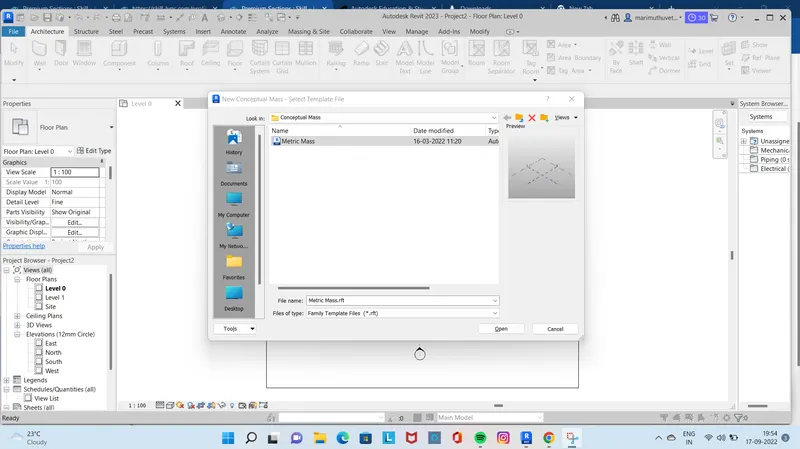
- Go for an elevation view at east to add the level at 12' at the level 2
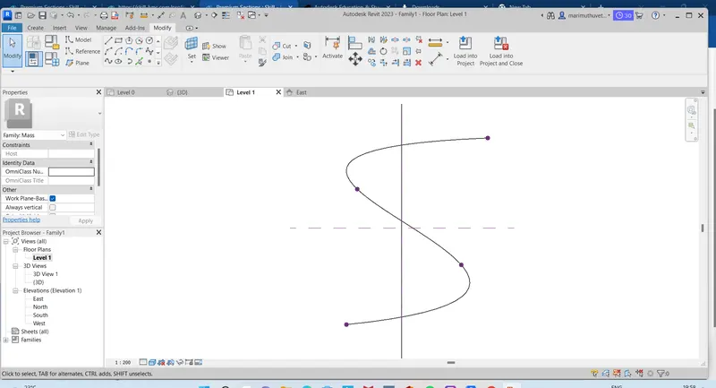
- And next to click the model choose the spiral line
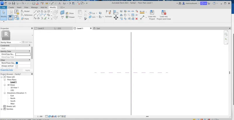
The sp line as an to the curve position at the intervels
After that go for an 3d view
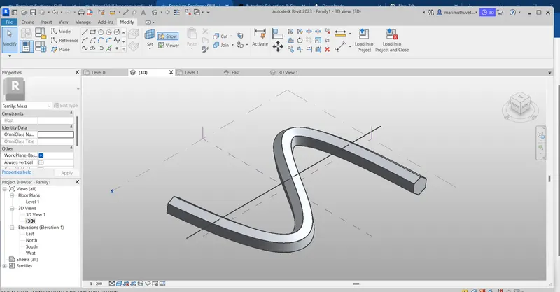
After that choose the ppentagon and layed at the points
After that choose the curve line and the triangualr bent
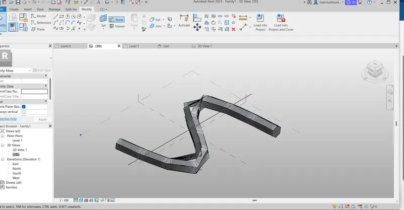
RESULT:
Finally we draw the curve line using tringle bent
5) Use Dynamo to work on developing a Parametric Stadium. List your parameters and use the visual programming approach to complete the modelling, You can use the concepts discussed in parametric high rise tower in class for reference.
INTRODUCTION:
Dynamo is, quite literally, what you make it. Working with Dynamo may include using the application, either in connection with other Autodesk software or not, engaging a Visual Programming process, or participating in a broad community of users and contributors.
AIM:
To Use Dynamo to work on developing a Parametric Stadium
COMMANDS ARE USED:
- Manage
- Dynamo
- Integer slider
- Code block
- Point by co ordinates
- Rotate
- Surface by loft
- List create
- Range
- Nurbs curve
- Mathsin
PROCEDURE:
- To Open the revit software and click architectural template go for manage tab click on dynamo .
- Next add an integrer slider
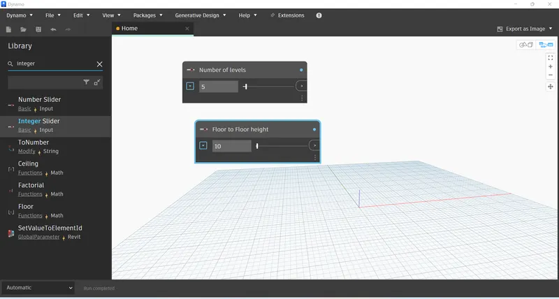
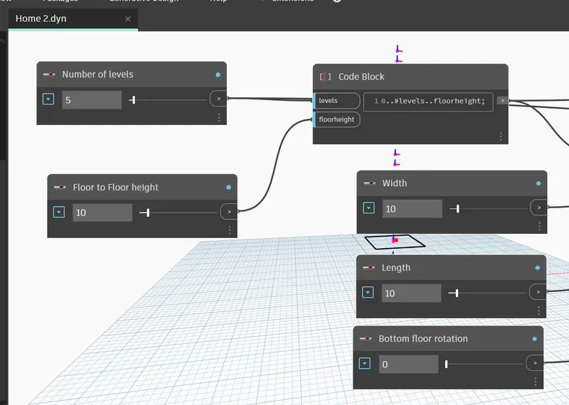
Renamed as Floor to floor height and number of levels @10,5
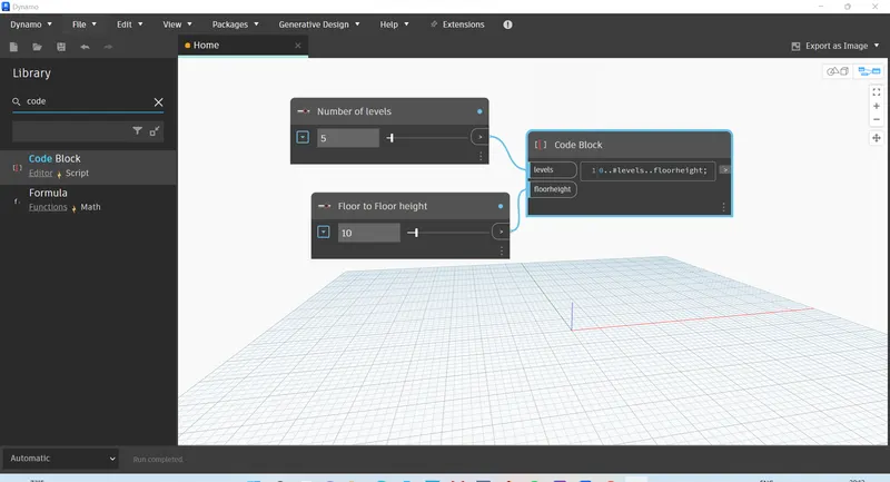
Next add the code block and mentioned as 0..#levels and first floor height and connected to this
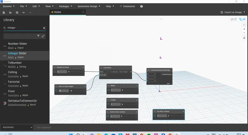
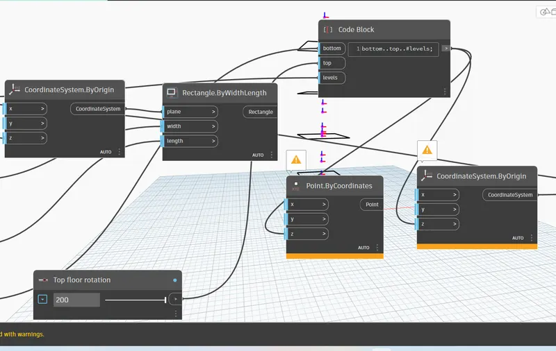
Add the integrer slider as width and length @10,10 and at bottom floor and top floor respectively @200,0
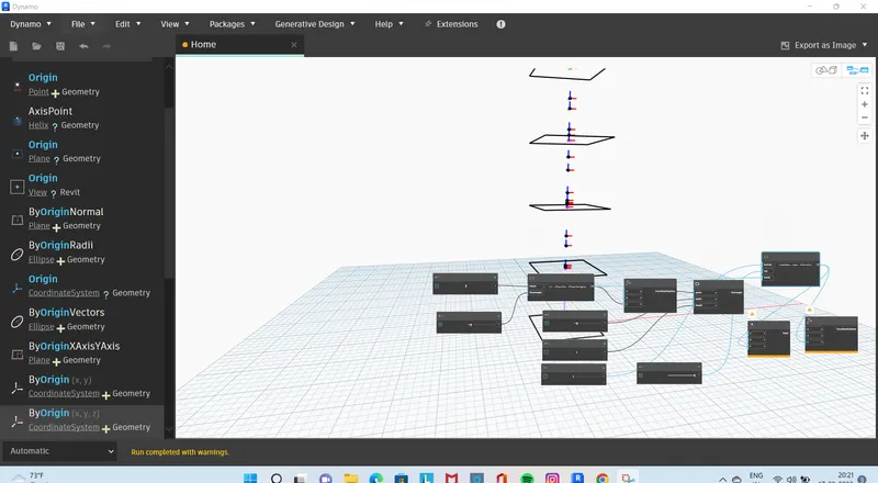
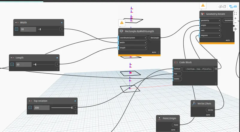
Add point co ordinate system and co ordinate system to the orgin connected to this and thhose are connected with the rectangle width and length
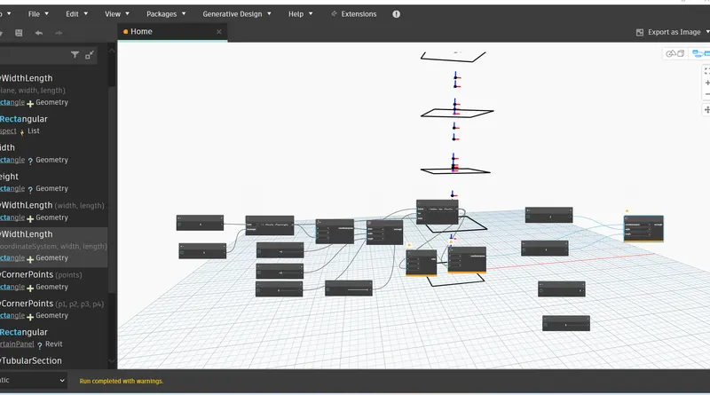
- Add to the point orgin to connect the orgin of geometric
- After that the z axis to connect the axis and code block as connected to the degree
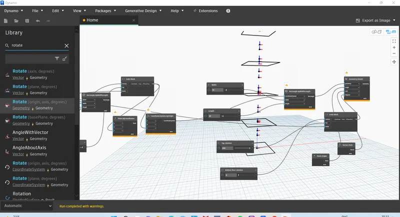
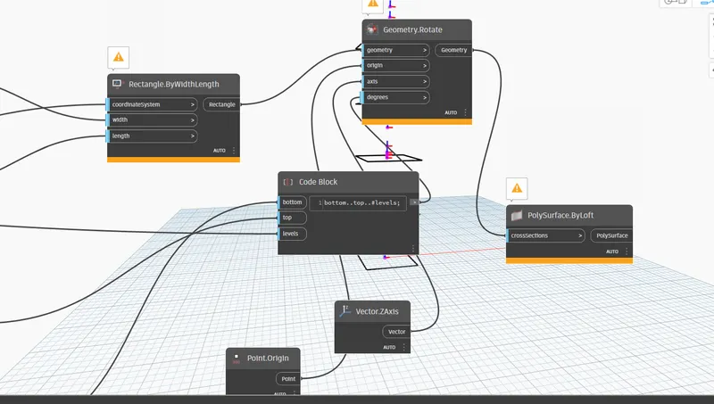
- Add an the geometric rotate to connect the axis , orgin, degree, geometry
- Add the poly surface loft
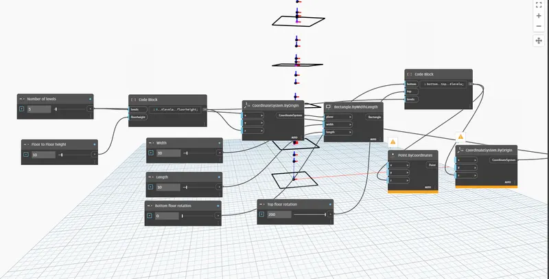
After that Connected to the levells and connected to the co ordinated system to the geometry
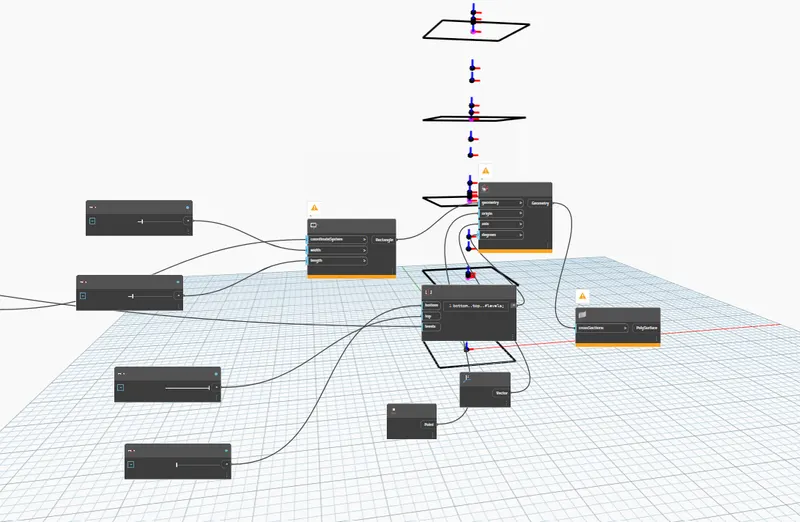
RESULT:
Finally we draw the paramatric system
Noted:
In my dynamo drawing the loft is not obtained pls check rectify it i have attached the drawing