Creating Conceptual mass in REVIT and Creation of Sinusoidal curve and a Parametric stadium using Dynamo
1) Using Dynamo create a set of sinusoidal points and create a curve and create a surface out of the curve.
AIM:
Using Dynamo create a set of sinusoidal points and create a curve and create a surface out of the curve.
PROCEDURE:
Dynamo is an open source visual programming language for Revit, written by designers and construction professionals. It is a programming language that allows you to type lines of code; while also creating an algorithm that consists of nodes.
Dynamo provides open source graphical programming, which enables custom computational design and automation processes for the building information modeling (BIM) process. Dynamo is more than a modeling interface.
To create a sinusoidal curve go to Dynamo under manage tab
To create a integer slider search for integer slider in a search tab & after creating integer slider press ctrl+c to create another 2 integer slider
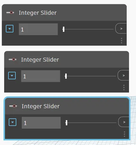
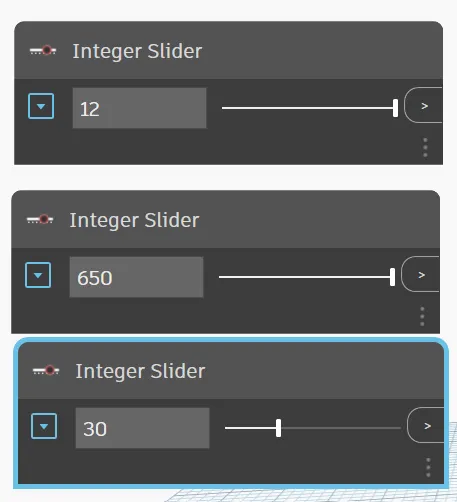
Increase the value of the integer slider created
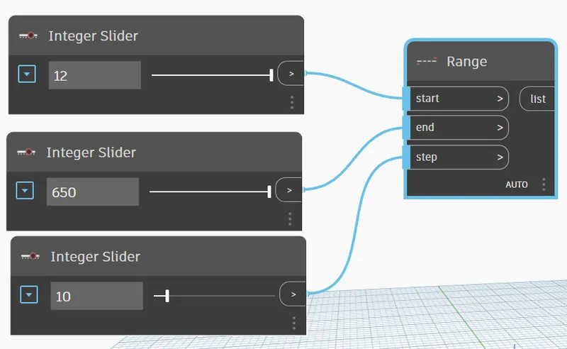
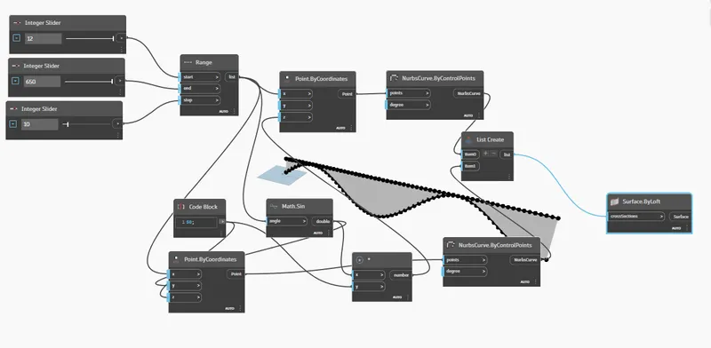
To create a range type range in the search bar ,now connect the first created integer slide to start,second to end,third to step
Create point.by coordinate ,for that type point.bt coordinate in search bar
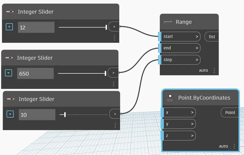
Create another code block & point by coordinate
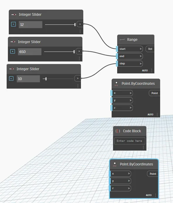
To create a sinusoidal points to curve type math.sin
Connect the range to point by coordinate
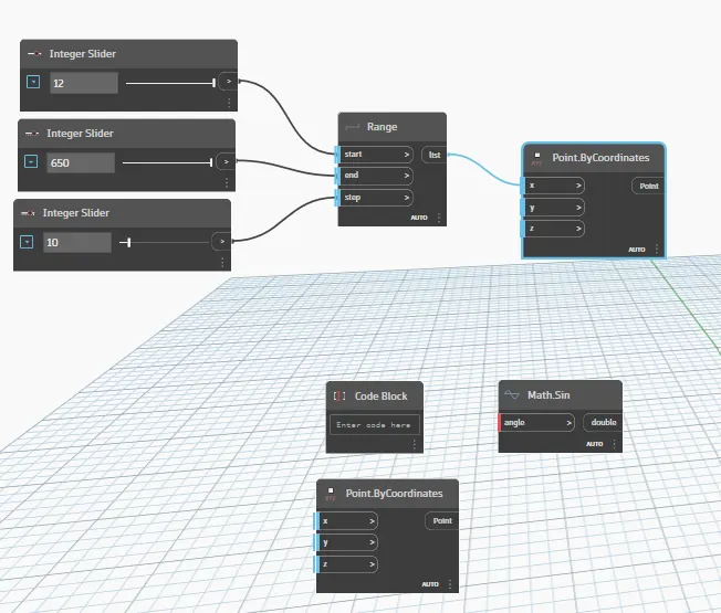
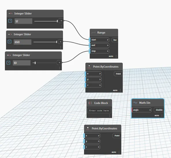
Provide code block as 50
Connect the range with the angle
Connect the range to X coordinate
To create a multiplication code block type product in search bar
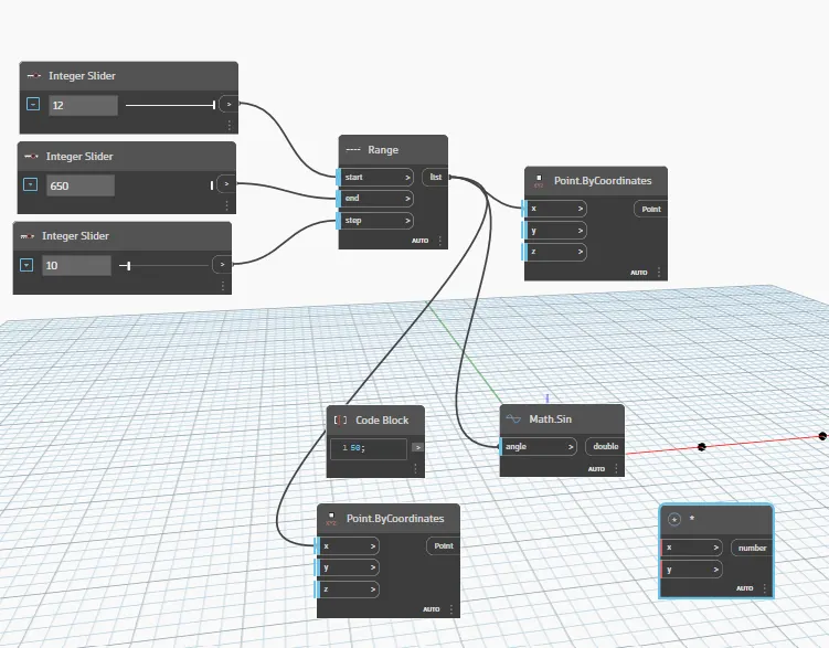
Connect code block to z coordinate
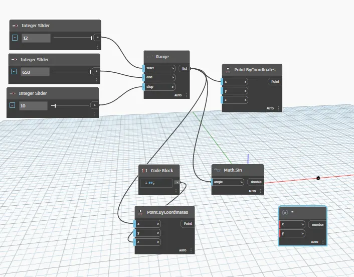
Connect math.sin to y coodrinate
Connect math.sin to product x
Connect code block to Y coordinate
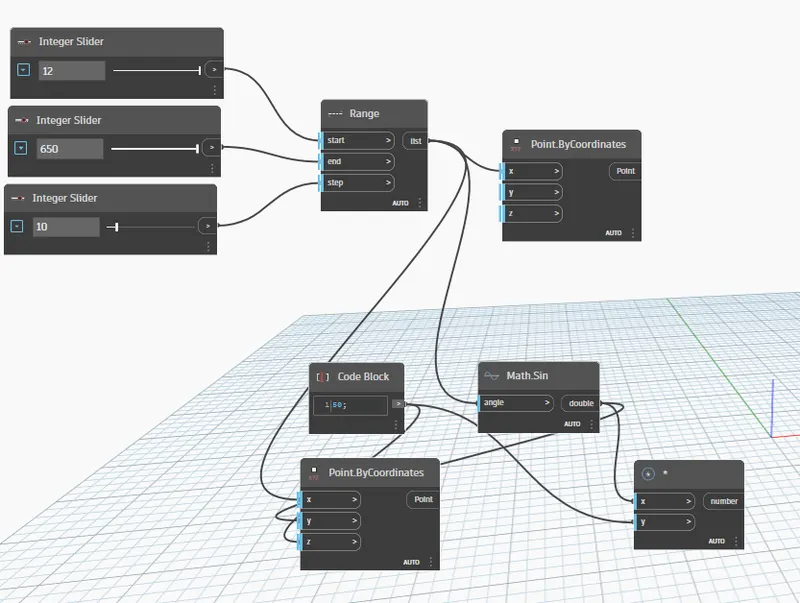
Connect product varient to z coordinate
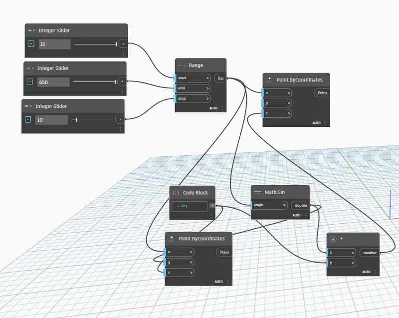
We created a sinusoidal point
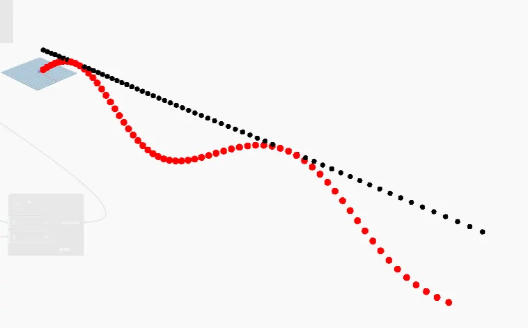
To create sinusoidal curve insert nurbs by coordinate
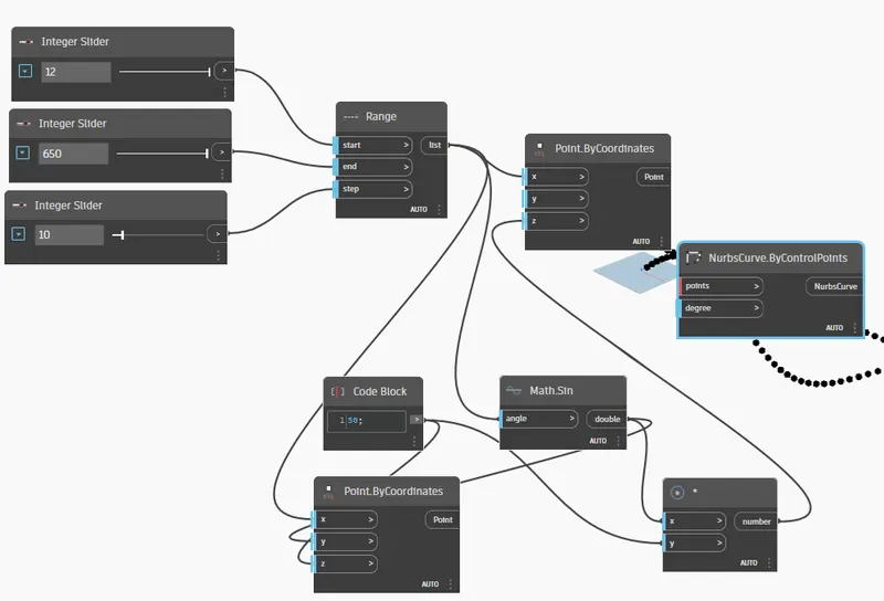
Create a list & create another nurbs.by coordinate
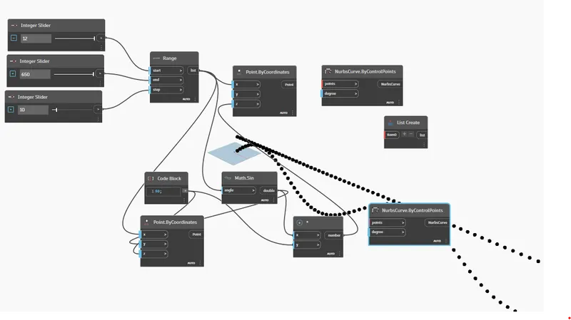
Connect points of points by cooordinate to points of nurbs.by coordinate
Connect another points of points by cooordinate to points of nurbs.by coordinate
Press + in list create to create another item
Now connect one nurbs curve to item 0 & another nurbs curve item 1
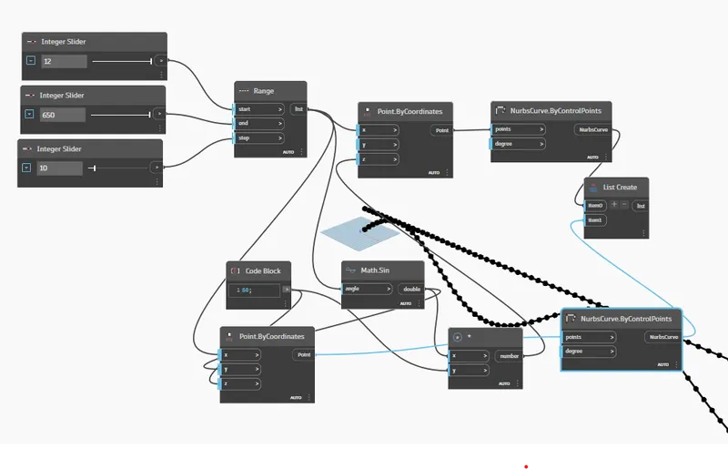
Now points & curves are created
Now create the surface & connect lis to cross section
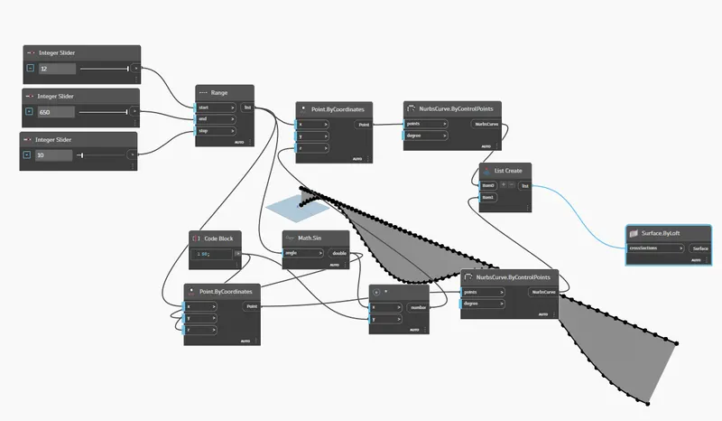
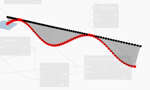
RESULT:
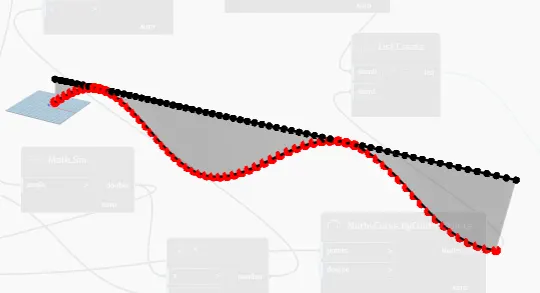
Using dynamo Sinusoidal point ,curve & surface are successfully created
2) Create a conceptual layout of floor plan in dynamo . Using the tools available in dynamo link the lines to appropriate model elements in Revit by choosing the wall types and wall parameters. Make use of the sliders to slide through the height of the wall and length of the wall.
AIM:
Create a conceptual layout of floor plan in dynamo . Using the tools available in dynamo link the lines to appropriate model elements in Revit by choosing the wall types and wall parameters. Make use of the sliders to slide through the height of the wall and length of the wall.
PROCEDURE:
Dynamo is an open source visual programming language for Revit, written by designers and construction professionals. It is programming language that allows you to type lines of code; while also creating an algorithm that consists of nodes.
Dynamo provides open source graphical programming, which enables custom computational design and automation processes for the building information modeling (BIM) process. Dynamo is more than a modeling interface.
Open Dynamo create 2 integer slider & assign the value as 100
To draw the wall insert 4 points by coordinate
Connect integer slide to x,y coordinates
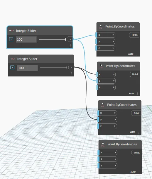
4 points were created
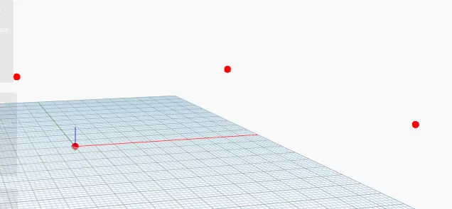
Now create the line through the point created
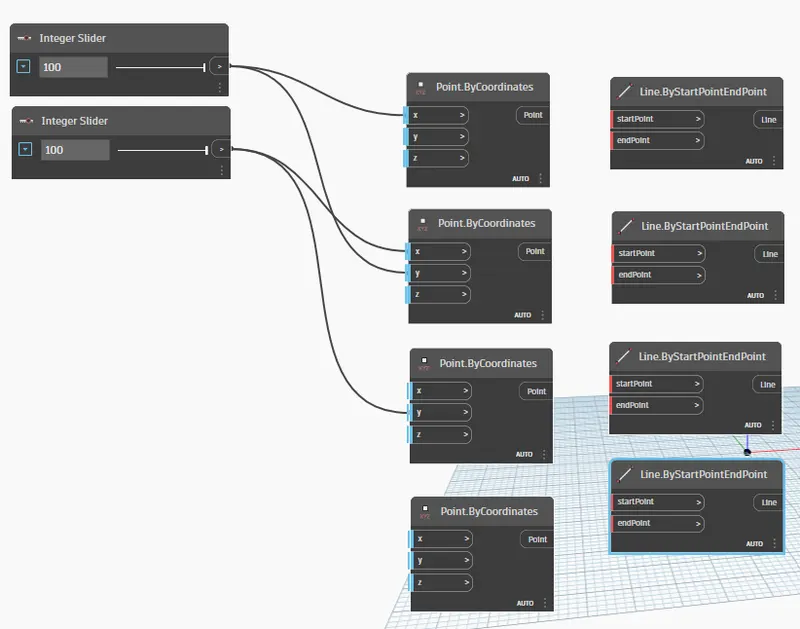
Connect the points by coordinate points to line start point & end point created
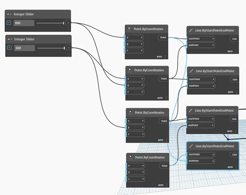
Now the wall is created
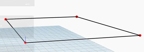
To create a complete wall connect the line to list created
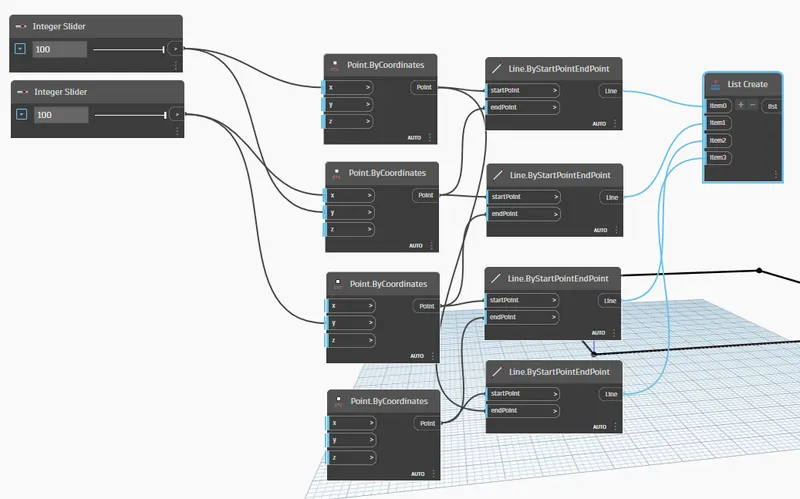
Set the levels,wall types,integer slider
Choose the levels,wall types & integer slider
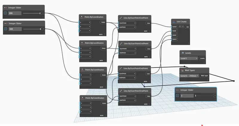 Create wall by curve & height
Connect list to curve
Connect level to level
Connect wall type to wall type
Connect integer slide to height
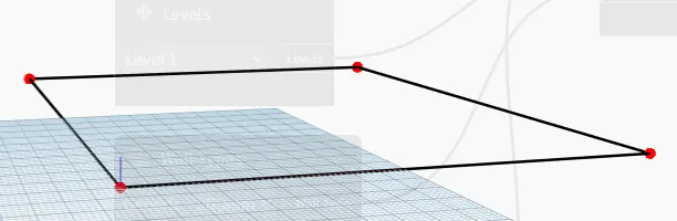
Cross check the created wall in revit
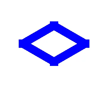 To create a floor insert floor types & floor.by outline types and level
Connect list created to outline curve
Choose floor type ,connect floor type to floor.by outline type and level
Connect level to level
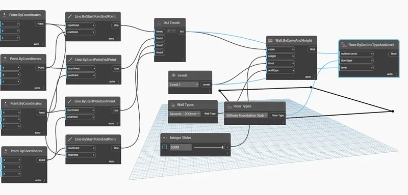
Cross check the created floor & wall in revit
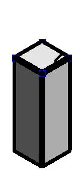
RESULT:
Using wall types,levels,floor the floor & wall has successfully created in Dynamo
3) Create an array of model elements in Revit. Use dynamo to vary the properties of model elements by using the slider or code block
AIM:
Create an array of model elements in Revit. Use dynamo to vary the properties of model elements by using the slider or code block
PROCEDURE:
In a Revit model or family, you can use the Array tool to create several instances of one or more elements, and manipulate them simultaneously. Create a radial array when the elements follow an arc. Create a linear array when the elements follow a straight line.
The Array tool creates a linear or radial array of selected elements. Use the Array tool to create several instances of one or more elements and manipulate them simultaneously. Array members can belong to a group; therefore, you can add or remove items from the group.
Dynamo is an open source visual programming language for Revit, written by designers and construction professionals. It is programming language that allows you to type lines of code; while also creating an algorithm that consists of nodes.
Dynamo provides open source graphical programming, which enables custom computational design and automation processes for the building information modeling (BIM) process. Dynamo is more than a modeling interface.
Created 4 Architectural column
Select multiple model elements in Dynamo
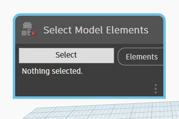
Insert set rotation & integer slider
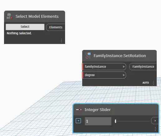
Select all the model elements that created in Revit
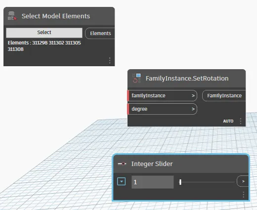
Set rotation as 45deg & connect elements with family instance & integer slider with deg
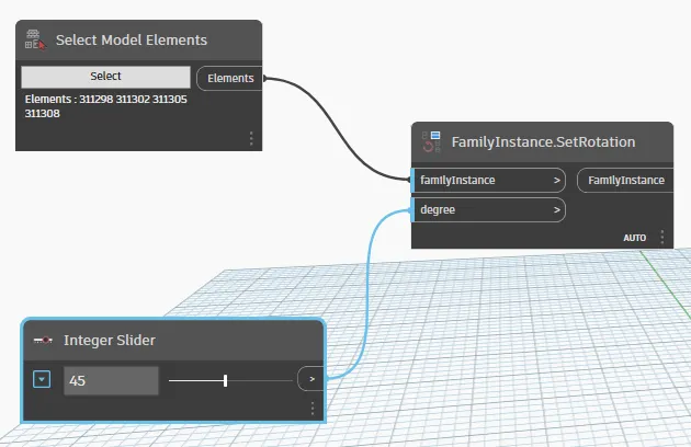
Now the column created in revit is rotated to 45deg

RESULT:
Array of model elements is created ,using slider in Dynamo the properties of model elements varied succesfully
4) Create a conceptual mass in Revit and develop a parametric column by dividing the surfaces and apply the concepts similar to used in parametric walkway modelling. Use triangular bent or square shaped panels to add finish to the parametric column
AIM:
Create a conceptual mass in Revit and develop a parametric column by dividing the surfaces and apply the concepts similar to used in parametric walkway modelling. Use triangular bent or square shaped panels to add finish to the parametric column
PROCEDURE:
Creating conceptual mass families means that the mass is external to the project. It uses the same tools to create the mass family, which is then saved and loaded into the project
The term parametric refers to the relationships among all elements of the model that enable the coordination and change management that Revit provides. These relationships are created either automatically by the software or by you as you work.
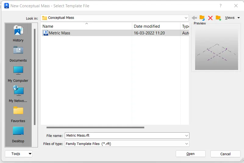
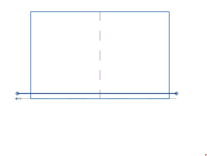
Go to file>New >Conceptual mass>Metric mass
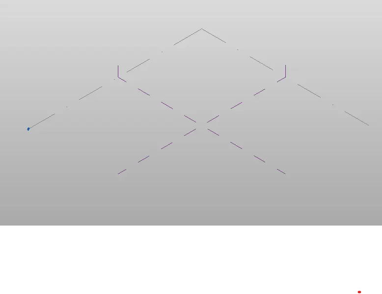
Created one more level in elevation
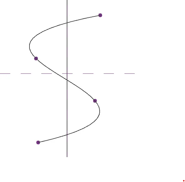
Go to level 1 ,model option >spline option>Create a spline like a curve
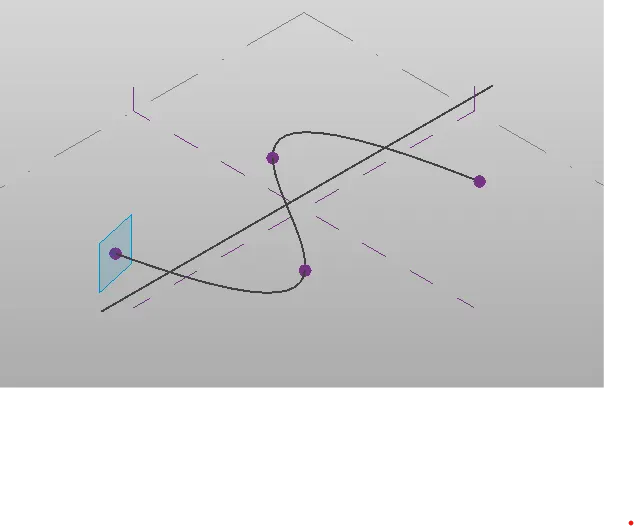
To create a plane go to 3d view choose set option>show
Place circumscribed polygon at a distance of 12'
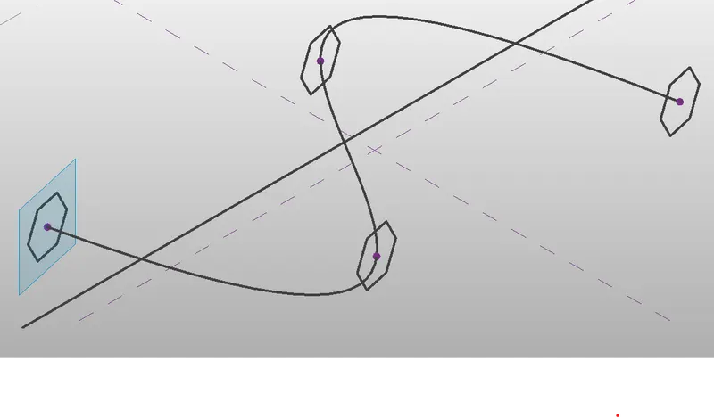
Now to convert the created spline into form ,click the created curve & by pressing ctrl button select the first cfreated polygon ,select create form option ,choose solid form.
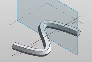
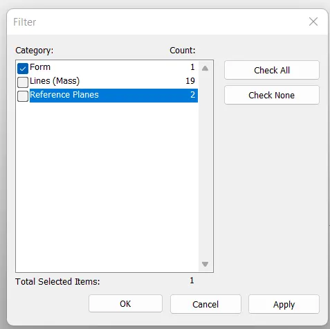
Now to divide the surface select the entire curve created ,go to filter option,select only form & give ok
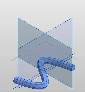
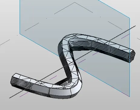
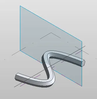 Now to create the triangular bend icon ,select all,click Divide surface,from the properties choose the triangular pattern
now the triangular bend has been created.
RESULT:
Created a conceptual mass in Revit and developed a parametric column by dividing the surfaces and applied the concepts similar to used in parametric walkway modelling. Used triangular bent to add finish to the parametric column
5) Use Dynamo to work on developing a Parametric Stadium. List your parameters and use the visual programming approach to complete the modelling, You can use the concepts discussed in parametric high rise tower in class for reference.
AIM:
Use Dynamo to work on developing a Parametric Stadium. List your parameters and use the visual programming approach to complete the modelling, You can use the concepts discussed in parametric high rise tower in class for reference.
PROCEDURE:
Dynamo is an open source visual programming language for Revit, written by designers and construction professionals. It is programming language that allows you to type lines of code; while also creating an algorithm that consists of nodes.
Dynamo provides open source graphical programming, which enables custom computational design and automation processes for the building information modeling (BIM) process. Dynamo is more than a modeling interface.
Open Dynamo under manage tab.
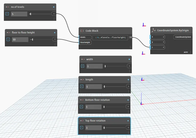
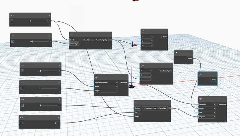
Create 2 integer slider ,rename it as no. of levels & givethe value as 5,floor to floor height & value as 10
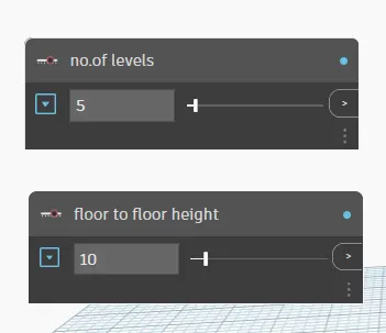
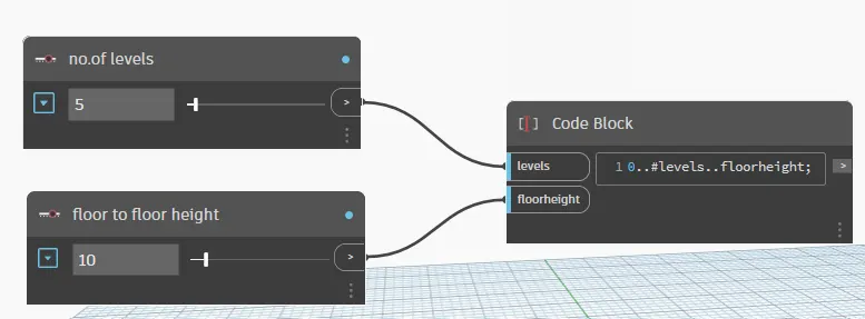
Insert code block ,manually provide some codes
Connect level to level & floor height to floor height
Insert points by coordinates system
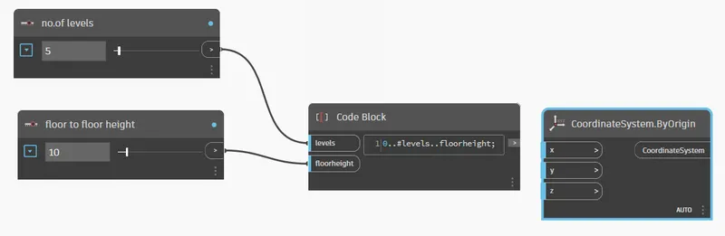
Connect code block to z coordinate
Insert 4 integer slider & rename it as width,length,bottom floor rotation,top floor rotation
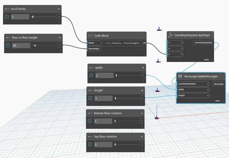
Insert recatangle by width length
Provide width & length value as 10
connect cs to cs,length to length,width to width
Provide value of bottom floor rotation to 0 & top floor rotation to 200
Insert another code block for bottom & provide codes
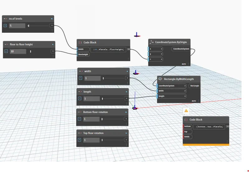
Connect bottom to bottom,top to top,no.of levels to levels
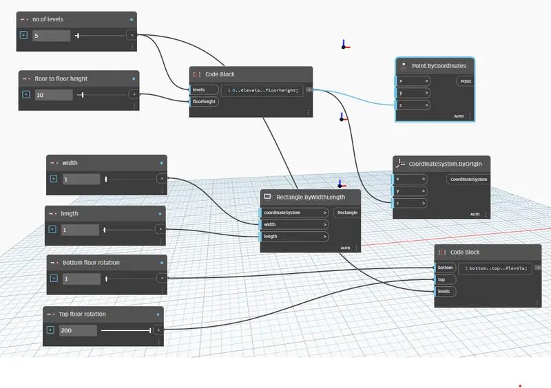
Insert origin
Insert vector zaxis
Insert geometry.rotate
Connect reactangle to geometry,origin to point origin,vector to axis,degree to code block
Insert polysurface.by loft & connect geometry to coodrinates
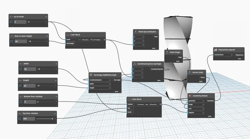
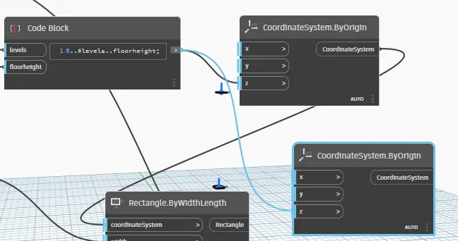
Parametric structure using code block has been created
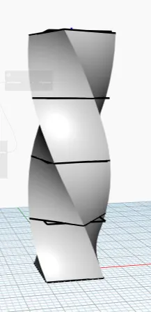
RESULT:
Using Dynamo parametric stadium has been succesfully created