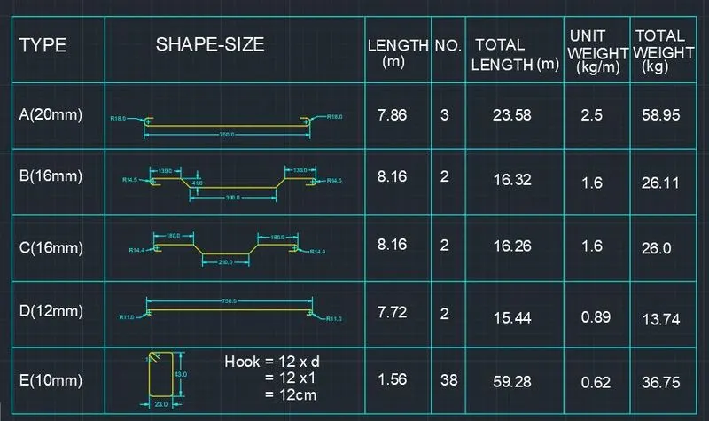
Creating Bar Bending schedule, Different Door types, and Creation of standard drawing templates using AutoCad
AIM1: To create the templates and need to take the size of title block as per industry standards. And need to save them as a block names as Customl_titlebox and Custom title bar.
INTRODUCTION:
- Drawing template files are drawings that store styles, settings, layers, and layouts in a drawing including title blocks.
- When you create a new drawing based on a drawing template, the new drawing gets a copy of the styles in the template, but it is a one-time copy.
PROCEDURE:
Step:-1
- First we need to draw the line horizontal line with the length of 66.63mm
- Next we need to draw the line vertically upwards with the length of 158mm.
- Next again draw the line horizontally backwards with the length of 66.63mm.
- Next join the previous line and the first line to form a rectangle.
- Next we take the first row of offset with the length of 5mm at the top.
- Next we draw the third row of offset with the length of 5mm. the second row of offset with the length of 10mm.
- Draw the fourth row of offset with the length of 5mm.
- Draw the fifth row of offset with the length of 8mm.
- Draw the sixth row of offset with the length of 30mm.
- Draw the seventh row of offset with the length of 15mm.
- Draw the eighth row of offset with the length of 15mm.
- Draw the 9 th row of offset with the length of 20mm.
- Draw the 10th row of offset with the length of 20mm.
- Draw the 11th row of offset with the length of 10mm.
- Draw the 12th row of offset with the length of 15mm.
- Next we use the text command to fill in the rows and columns.
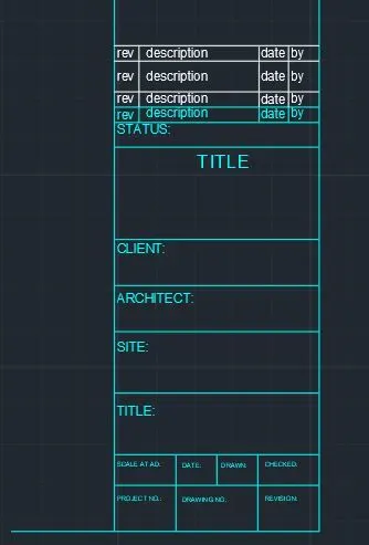
- After entering the texts we need to save the title box as a block with the name as Custom 1_titlebox
- We use the block command to save the title box as a block, as shown in the below picture.
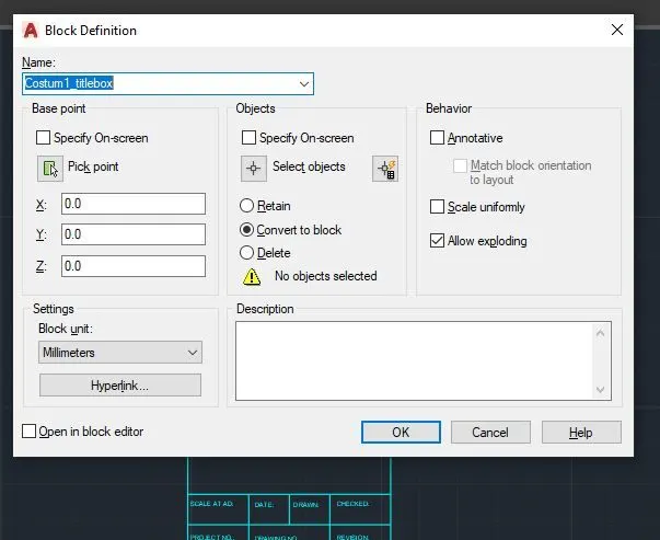
- enter the block command in the command, Next click the pick point and pick the point of the title box box. Next select the objects in the figure and press enter.
- Then select the option 'convert to box. Next we have to turn on the scale uniformly.Then after press the ok button to finish.
- Finally the title box is created as a block with the name as Custom1_ titlebox.
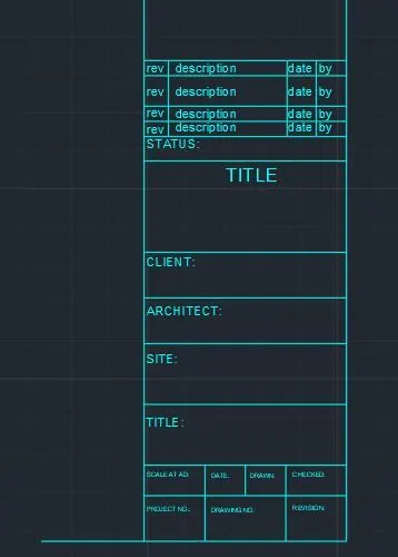
Step:-2
- First we have to draw the horizontal line with the length of 252mm.
- Next we have to draw the vertical line from previous line with the length of 46mm.
- Next again draw the horizontal line from the previous line with the length of 252mm.
- Next we join the first line and the last line at the left side of the figure. Next we have to draw the rectangle at the right corner of the figure at the top. Next we need to draw remaining rows and columns required in the drawing.
- Next we use the single text command to write the text in the rows and columns where ever required.
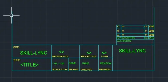
- After entering the texts we need to save the title box as a block with the name as Custom2_titlebox
- We use the block command to save the title box as a block, as shown in the below picture.
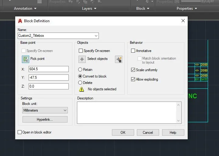
- enter the block command in the command, Next click the pick point and pick the point of the title box box. Next select the objects in the figure and press enter.
- Then select the option 'convert to box. Next we have to turn on the scale uniformly. Then after press the ok button to finish.
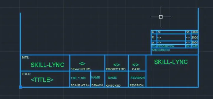
- Finally the title box is created as a block with the name as Custom2_ titlebox.
RESULT:
AIM-2: To create the doors type for warehouse and need to create each door type as per standard size. And to create the blocks of door type after creating them.
INTRODUCTION:
- Doors are drawn in plan view as a heavy line in small-scale drawings, or as a double line, to indicate their thickness, in large scaled plans
- A swing door has a thinner curved line drawn to denote the direction of its swing.
- The drawings of doors are drawn by the architects in the construction projects.
PROCEDURE
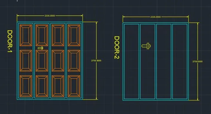
Step1:
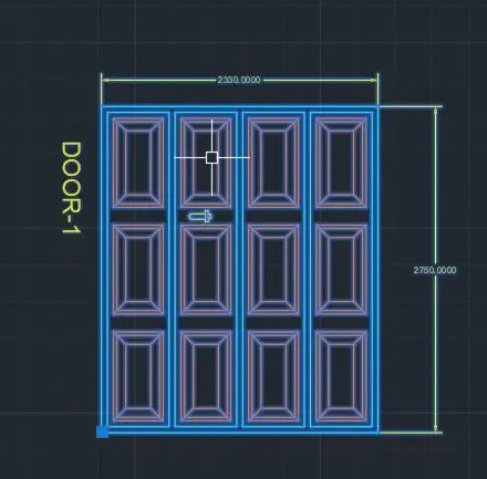
- First we draw the the with the length of 2300mm horizontally forward.
- Next we need to draw the vertical line upwards with the length of 2750mm. Again draw the line horizontally backwards at the top with the length of 2330mm.
- Now join the first line and the previous line to form the rectangle.
- Now draw the lines inside the rectangle by taking suitable offsets.
- Now draw the boxes inside the constructed door with suitable dimensions.
- Now, using dim and text command, give the dimensions and name to the drafted drawing.
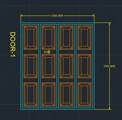
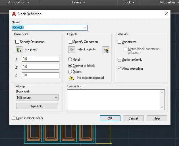
- After entering the texts we need to save the figure as a block with the name as DOOR-1
- We use the block command to save the figure as a block, as shown in the below picture.
- enter the block command in the command, Next click the pick point and pick the point of the figure. Next select the objects in the figure and press enter.
- Then select the option 'convert to box. Next we have to turn on the scale uniformly. Then after press the ok button to finish.
- Finally the figure is created as a block with the name as DOOR-1.
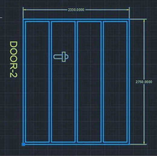
Step-2:
- Using, the line, offset and trim command, draw the figure of the door according to the given sketch with the given dimensions.
- Using text and dim command, give the name and dimensions to the figure.
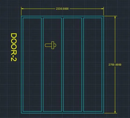
- After entering the texts we need to save the figure as a block with the name as DOOR2
- We use the block command to save the figure as a block, as shown in the below picture.
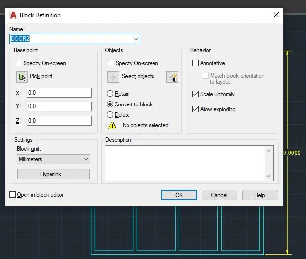
- enter the block command in the command, Next click the pick point and pick the point of the figure. Next select the objects in the figure and press enter.
- Then select the option 'convert to box. Next we have to turn on the scale uniformly. Then after press the ok button to finish.
- Finally the figure is created as a block with the name as DOOR2.
RESULT:
AIM-3: To create the electric symbols as block with the name. And to create the blocks and arrange them in the legend.
INTRODUCTION:
- Electrical symbols are used for universal recognition of the building plan by different persons who will be working on the construction.
- Not all possible electric symbols used on a certain plan, so the symbols used in the current home plan are included to a legend.
- The electrical home plan may be added as a separate document to a complete set.
PROCEDURE:
Step: 1
- First we need to draw the line horizontal line with the length of 200mm.
- Next we need to draw the line vertically upwards with the length of 100mm.
- Next again draw the line horizontally backwards with the length of 200mm.
- Next join the previous line and the first line to form a rectangle.
- Next we draw the ten rows and six columns with alternate distances.
Step:2
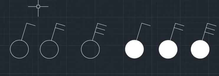
- Using, Line, circle, offset, trim and Hatch command, Single gang switch, double gang switch, triple gang switch, Single twoway switch, double twoway switch, triple twoway switch are drawn.
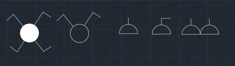
- Using, Line, circle, offset, trim and Hatch command, switch socket, switch serial, switch cross, single socket forelamp, double socket, are drawn.
- Using, Line, circle, offset, trim and Hatch command, floor single socket, floor double socket, floor single socket for lamp, single floor socket telephone, floor double socket telephone, telephone socket and internet socket are drawn.

- Using, Line, circle, offset, trim and Hatch command, TV socket, weather proof socket, deckbase station, wall bracket and picture lamp are drawn.
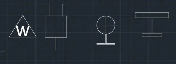
Step:3:
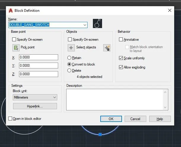
- We use the block command to save the figures as a block, as shown in the below picture.
- enter the block command in the command, Next click the pick point and pick the point of the figure. Next select the objects in the figure and press enter.
- Then select the option 'convert to box. Next we have to turn on the scale uniformly. Then after press the ok button to finish.
- Finally the figure is created as a block with the name as single_gang_switch.
- Repeat the same steps for converting all the drawn figures into blocks.\
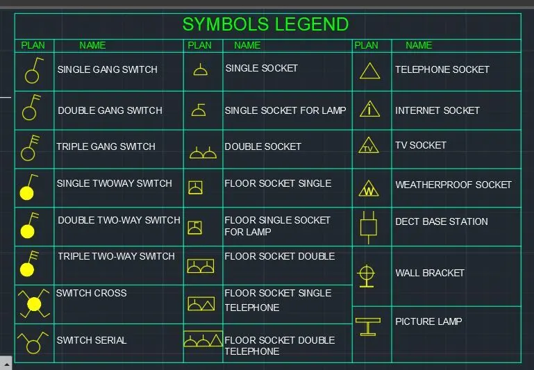
- Next, put the converted blocks inside the constructed table and fill in the table with their respective texts with text command.
RESULT:
AIM-4: To create the door type for residential building and to save the name of the blocks as type.
INTRODUCTION:
- Doors are drawn in plan view as a heavy line in small-scale drawings, or as a double line, to indicate their thickness, in larger- scaled plans.
- A swing door has a thinner curved line drawn to denote the direction of its swing.
- The drawings of doors are drawn by the architects in the construction projects.
PROCEDURE:
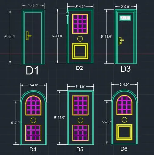
Step1:
- Using, the line, offset and trim command, draw the figure of the door according to the given sketch with the given dimensions.
- Using text and dim command, give the name and dimensions to the figure.
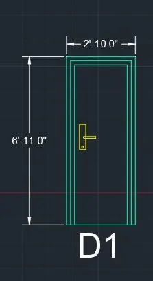
- After entering the texts we need to save the figure as a block with the name as D1.
- We use the block command to save the figure as a block, as shown in the below picture.
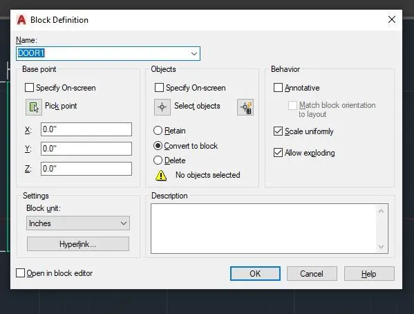
- enter the block command in the command, Next click the pick point and pick the point of the figure. Next select the objects in the figure and press enter.
- Then select the option 'convert to box. Next we have to turn on the scale uniformly. Then after press the ok button to finish.
- Finally the figure is created as a block with the name as D1.
Step2:
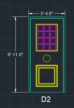
- Using, the line, offset and trim command, draw the figure of the door according to the given sketch with the given dimensions.
- Using text and dim command, give the name and dimensions to the figure.
- After entering the texts we need to save the figure as a block with the name as D2
- We use the block command to save the figure as a block, as shown in the below picture.
- enter the block command in the command, Next click the pick point and pick the point of the figure. Next select the objects in the figure and press enter.
- Then select the option 'convert to box. Next we have to turn on the scale uniformly. Then after press the ok button to finish.
- Finally the figure is created as a block with the name as D2.
Step3:
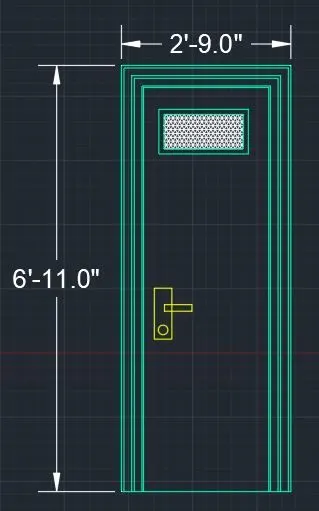
- Using, the line, offset and trim command, draw the figure of the door according to the given sketch with the given dimensions.
- Using text and dim command, give the name and dimensions to the figure.
- After entering the texts we need to save the figure as a block with the name as D3
- We use the block command to save the figure as a block, as shown in the below picture.
- enter the block command in the command, Next click the pick point and pick the point of the figure. Next select the objects in the figure and press enter.
- Then select the option 'convert to box. Next we have to turn on the scale uniformly. Then after press the ok button to finish.
- Finally the figure is created as a block with the name as D3.
Step4:
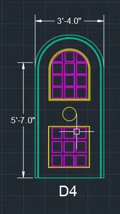
- Using, the line, offset and trim command, draw the figure of the door according to the given sketch with the given dimensions.
- Using text and dim command, give the name and dimensions to the figure.
- After entering the texts we need to save the figure as a block with the name as D4
- We use the block command to save the figure as a block, as shown in the below picture.
- enter the block command in the command, Next click the pick point and pick the point of the figure. Next select the objects in the figure and press enter.
- Then select the option 'convert to box. Next we have to turn on the scale uniformly. Then after press the ok button to finish.
- Finally the figure is created as a block with the name as D4.
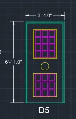
Step5:
- Using, the line, offset and trim command, draw the figure of the door according to the given sketch with the given dimensions.
- Using text and dim command, give the name and dimensions to the figure.
- After entering the texts we need to save the figure as a block with the name as D5
- We use the block command to save the figure as a block, as shown in the below picture.
- enter the block command in the command, Next click the pick point and pick the point of the figure. Next select the objects in the figure and press enter.
- Then select the option 'convert to box. Next we have to turn on the scale uniformly. Then after press the ok button to finish.
- Finally the figure is created as a block with the name as D5.
Step6:
- Using, the line, offset and trim command, draw the figure of the door according to the given sketch with the given dimensions.
- Using text and dim command, give the name and dimensions to the figure.
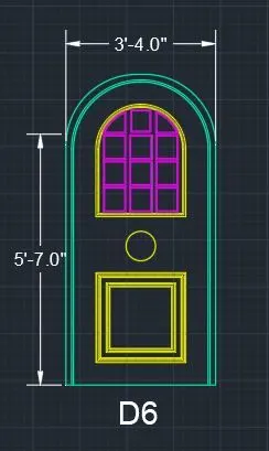
- After entering the texts we need to save the figure as a block with the name as DOOR2
- We use the block command to save the figure as a block, as shown in the below picture.
- enter the block command in the command, Next click the pick point and pick the point of the figure. Next select the objects in the figure and press enter.
- Then select the option 'convert to box. Next we have to turn on the scale uniformly. Then after press the ok button to finish.
- Finally the figure is created as a block with the name as DOOR2.
-
RESULT:
AIM-5: To create the bar shape as block with the name. And to create the blocks and arrange them in the table.
INTRODUCTION:
- Bar Bending Schedule is a definitive list of reinforcement bars for any structural element that includes a mark, shape, size, location, length, and bending details of the reinforcement. It is often referred to as BBS.
- Tabular view representation of each reinforcement bar used in any structural element is known as BBS.
PROCEDURE:
Step1:
- With line command, Horizontal and vertical lines of suitable length are drawn to create a rectangle.
- With offset command, offsets at suitable distances are drawn to create the rows and columns for the table.
- Finally, the table is created.
Step2:
- Using, the line, offset and trim command, draw the figure of the door according to the given sketch with the given dimensions.
- Using text and dim command, give the name and dimensions to the figure.
- After entering the texts we need to save the figure as a block with the name as A
- We use the block command to save the figure as a block, as shown in the below picture.
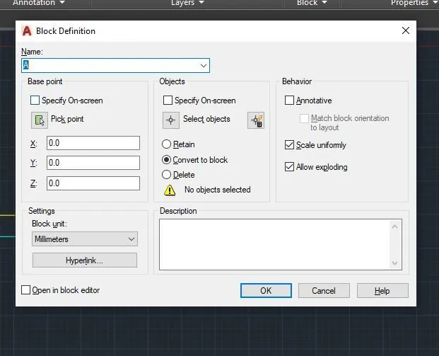
- Enter the block command in the command, Next click the pick point and pick the point of the figure. Next select the objects in the figure and press enter.
- Then select the option 'convert to box. Next we have to turn on the scale uniformly. Then after press the ok button to finish.
- Finally the figure is created as a block with the name as A.

Step3:
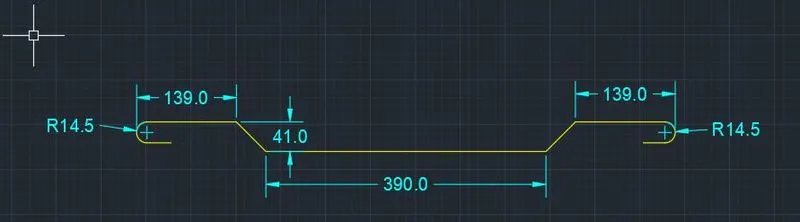
- Using, the line, offset and trim command, draw the figure of the door according to the given sketch with the given dimensions.
- Using text and dim command, give the name and dimensions to the figure.
- After entering the texts we need to save the figure as a block with the name as B
- We use the block command to save the figure as a block, as shown in the below picture.
- enter the block command in the command, Next click the pick point and pick the point of the figure. Next select the objects in the figure and press enter.
- Then select the option 'convert to box. Next we have to turn on the scale uniformly. Then after press the ok button to finish.
- Finally the figure is created as a block with the name as B.
Step4:
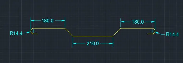
- Using, the line, offset and trim command, draw the figure of the door according to the given sketch with the given dimensions.
- Using text and dim command, give the name and dimensions to the figure.
- After entering the texts we need to save the figure as a block with the name as C
- We use the block command to save the figure as a block, as shown in the below picture.
- enter the block command in the command, Next click the pick point and pick the point of the figure. Next select the objects in the figure and press enter.
- Then select the option 'convert to box. Next we have to turn on the scale uniformly. Then after press the ok button to finish.
- Finally the figure is created as a block with the name as C.
Step5:
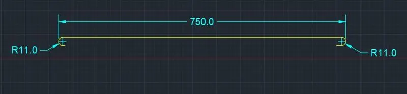
- Using, the line, offset and trim command, draw the figure of the door according to the given sketch with the given dimensions.
- Using text and dim command, give the name and dimensions to the figure.
- After entering the texts we need to save the figure as a block with the name as D
- We use the block command to save the figure as a block, as shown in the below picture.
- enter the block command in the command, Next click the pick point and pick the point of the figure. Next select the objects in the figure and press enter.
- Then select the option 'convert to box. Next we have to turn on the scale uniformly. Then after press the ok button to finish.
- Finally the figure is created as a block with the name as D.
Step6:
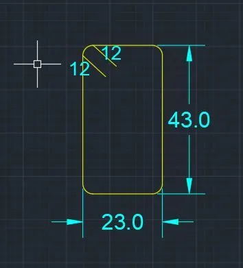
- Using, the line, offset and trim command, draw the figure of the door according to the given sketch with the given dimensions.
- Using text and dim command, give the name and dimensions to the figure.
- After entering the texts we need to save the figure as a block with the name as E
- We use the block command to save the figure as a block, as shown in the below picture.
- enter the block command in the command, Next click the pick point and pick the point of the figure. Next select the objects in the figure and press enter.
- Then select the option 'convert to box. Next we have to turn on the scale uniformly. Then after press the ok button to finish.
- Finally the figure is created as a block with the name as E.
- Finally, move the converted blocks inside the table and fill in the table with suitable information using text command.
RESULT: