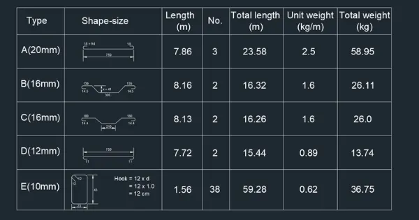
Creating Bar Bending schedule, Different Door types, and Creation of standard drawing templates using AutoCad
Q.1
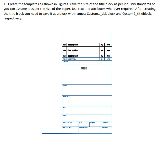
Answer. A
AIM :- To create template as shown in the figure above in Auto Cad.
Introduction :- The template is created in Auto Cad using rectengular block and text.
Procedure :
STEP 1 :-
- Open Autocad set Units and Decimal first
- Click on 'Layer Properties' in the layer panel on the Ribbon.
- Click on ' New Layer' to create the layers
- Select the Rectangle to create the box
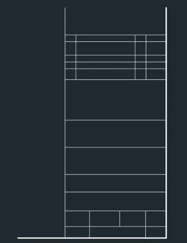
STEP 2:-
- Use the L command to draw the line
- Draw the lines to form the diffrent sections within the box
- Enter 'MTEXT' command in the command line
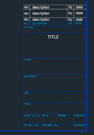
STEP 3:-
- Enter B in the comand promt
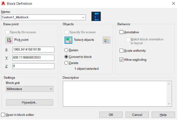
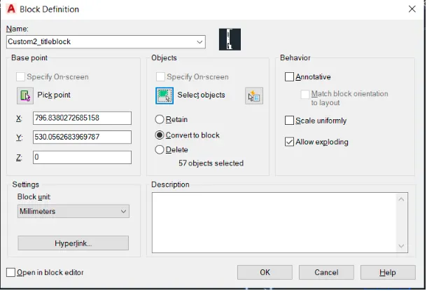
- In the Block Defination dialogue box,type in the name of block as Custom1_titleblock,pick the base point as the bottom right corner of the block
B. Custom2_tittleblock:
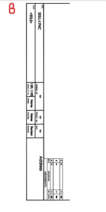
STEP 1 :-
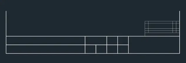
- Select rectangle tool by entering 'Rec' command in command tab
- Select the rectangle created and explode it
- Select the Line tool 'L' to create sections within the box
- Trim and erase unwanted lines
STEP 2 :-
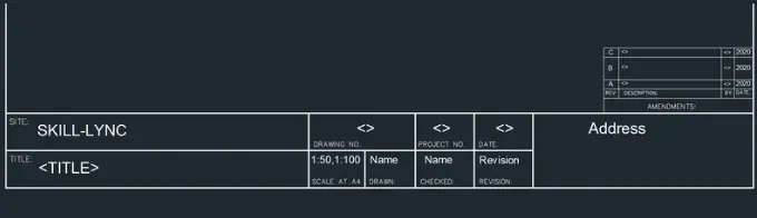
- Enter 'MTEXT' command in command tab
- Specifiy the start point of text as required.
- Provide the text height as 6
- Copy the text box to wherever necessary.
STEP 3:-
- Enter B in the command promt
- In the Block Definition dialogue box type in the name as Custom2_tittle, pick the base point as the bottom right corner of block
Result
Q.2
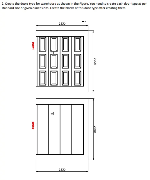
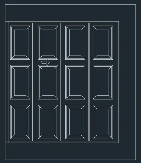
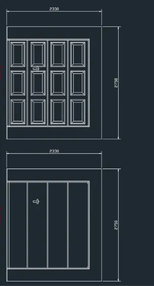
Ans. A. DOOR 1
Aim:- To create the door as shown in figure in Auto Cad
Introduction:- The doors are created in Auto cad using Rectangle Command and Line Tools.
Procedure:-
STEP 1
- Open Auto cad and set UNITS and limits
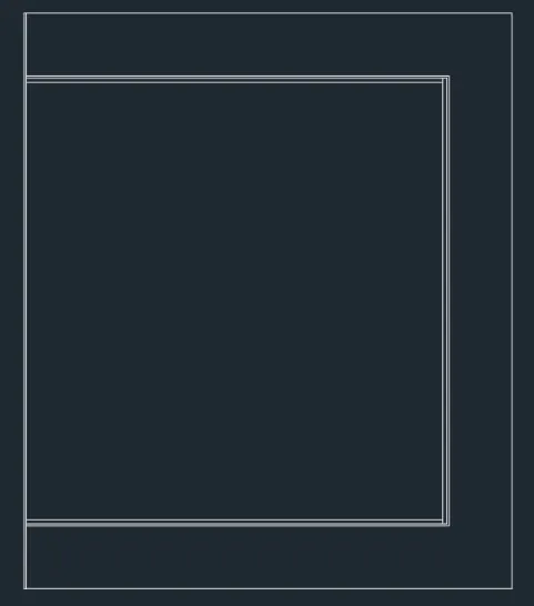
- Select the rectangle tool and create rectangle
- Specify the distance offset of 10 ,select left side of rectangle and then click on the inside
- Repeat the Offset specify the distance as 300 and then offset the other three sides of rectangle.
- Trim and erase unwanted lines
STEP 2
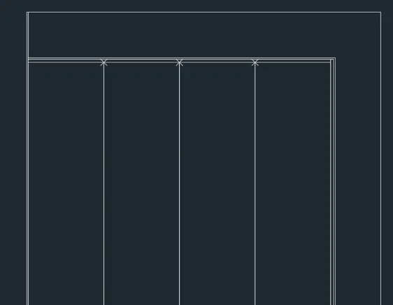
- Select the Divide tool from the draw panel.
- select the inner edge of the smaller rectangle and enter number of segments as 4
- Specify as offset distance of 10 select the section lines and click on either sides.
- Repeat offset specificy the distance of 50, select the inner edge of smaller rectangle and click inside
STEP 3
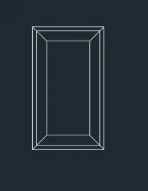
- Now draw single pannel and will copy the created pattern as shown in figure
- Select the rectangle tool and enter @ 350,600.
- Specify the Offset distance of 20 and select all sides of rectangle
STEP 4
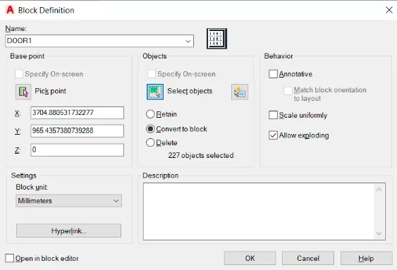
- Enter B in the command promt
- In the defination dialogue box,type in the name as DOOR1,pick the base point as the bottom right corner of the door
RESULT
B) DOOR2:
STEP 1
- Select the DOOR block and click on Explode icon on the Ribbon
- Copy the door frame and sections of DOOR1
- Enter B in the command promt
- In Block defination box type name of block as DOOR2, pick the base point as the bottom right corner of the door,
STEP 2
- Select the Dimension tool by entering DIM
- Select first point and second point of object to be measured
- Enter the text height and use ED command to edit the text boxes
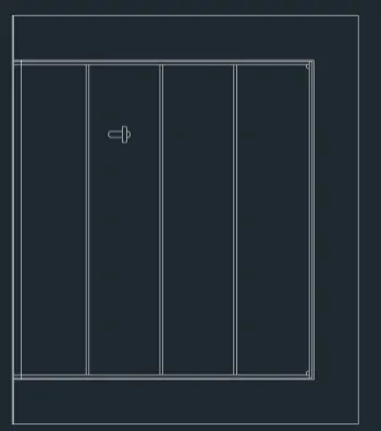
RESULT
Q.3
Ans:- 3
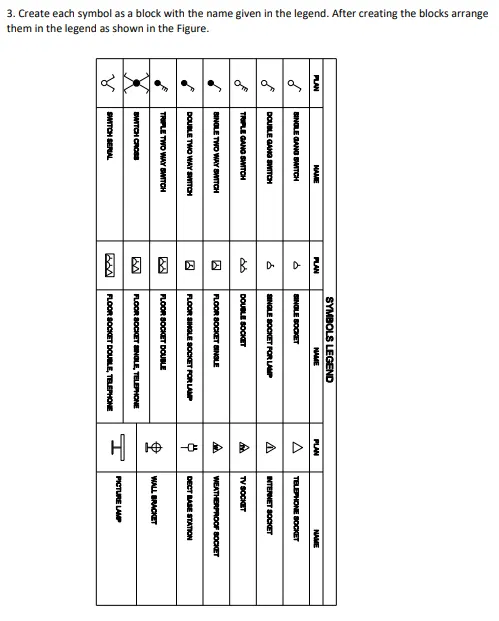
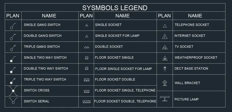
AIM:- To create each symbol as a block and arranging them accordingly in the lengend using Auto cad.
Introduction:- The symbols are created in auto cad using rectangle ,circle and line tools.
Procedure:-
STEP 1
- Open auto cad and set UNITS,LIMITS.
- Select the circle tool by entering C command
- Specify the center and enter the radius circle as 50
- Select the line tool and ortho off
- Draw an inclined line of length 100 from circle outer edge and another line of 50 length

STEP 2
- Enter B in the command promt
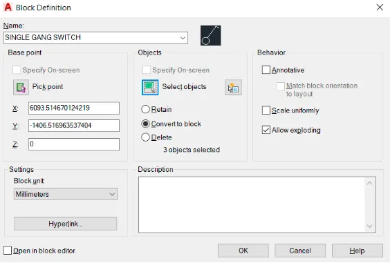
- In the Block Defination dialogue box,type in the name block as SINGLE GANG SWITCH, pick the base point as the centre of the circle
STEP 3
- Similarly as above draw and create another Block and type name as DOUBLE GANG SWITCH, pick the base point as the centre of the circle

STEP 4
- Similarly as above draw and create another Block and type name as TRIPLE GANG SWITCH, pick the base point as the centre of the circle

STEP 5
- Similarly as above draw and create another Block and type name as SINGLE TWO WAY SWITCH, pick the base point as the centre of the circle

STEP 6
- Similarly as above draw and create another Block and type name as DOUBLE TWO WAY SWITCH, pick the base point as the centre of the circle

STEP 7
- Similarly as above draw and create another Block and type name as TRIPLE TWO WAY SWITCH, pick the base point as the centre of the circle

STEP 8
- Similarly as above draw and create another Block and type name as SWITCH CROSS, pick the base point as the centre of the circle

STEP 9
- Similarly as above draw and create another Block and type name as SWITCH SERIAL, pick the base point as the centre of the circle

STEP 10
- Similarly as above draw and create another Block and type name as SINGLE SOCKET, pick the base point as the centre of the circle

STEP 11
- Similarly as above draw and create another Block and type name as SINGLE SOCKET FOR LAMP, pick the base point as the centre of the circle

STEP 12
- Similarly as above draw and create another Block and type name as DOUBLE SOCKET, pick the base point as the centre of the circle
STEP 13
- Similarly as above draw and create another Block and type name as FLOOR SOCKET SINGLE, pick the base point as the centre of the circle
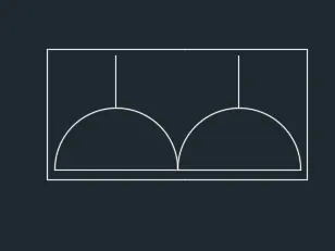
STEP 14
- Similarly as above draw and create another Block and type name as FLOOR SOCKET DOUBLE, pick the base point as the centre of the circle
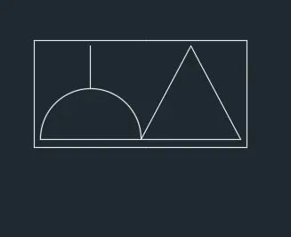
STEP 15
- Similarly as above draw and create another Block and type name as FLOOR SOCKET SINGLE,TELEPHONE pick the base point as the centre of the circle
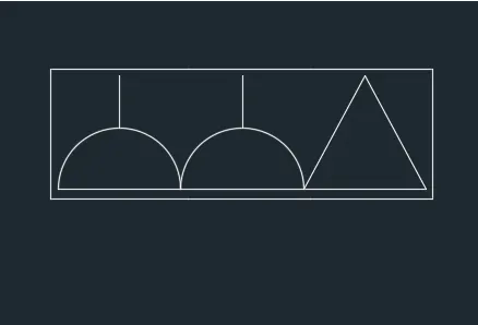
STEP 16
- Similarly as above draw and create another Block and type name as TELEPHONE SOCKET, pick the base point as the centre of the circle

STEP 17
- Similarly as above draw and create another Block and type name as INTERNET SOCKET, pick the base point as the centre of the circle

STEP 18
- Similarly as above draw and create another Block and type name as TV SOCKET , pick the base point as the centre of the circle

STEP 19
- Similarly as above draw and create another Block and type name as WEATHERPROOF SOCKET, pick the base point as the centre of the circle

STEP 20
- Similarly as above draw and create another Block and type name as DECT BASE STATION, pick the base point as the centre of the circle
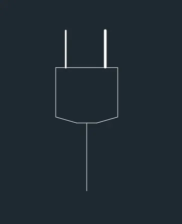
STEP 21
- Similarly as above draw and create another Block and type name as WALL BRACKET, pick the base point as the centre of the circle
STEP 22
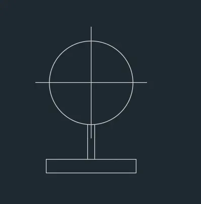
- Similarly as above draw and create another Block and type name as PICTURE LAMP, pick the base point as the centre of the circle
STEP 23
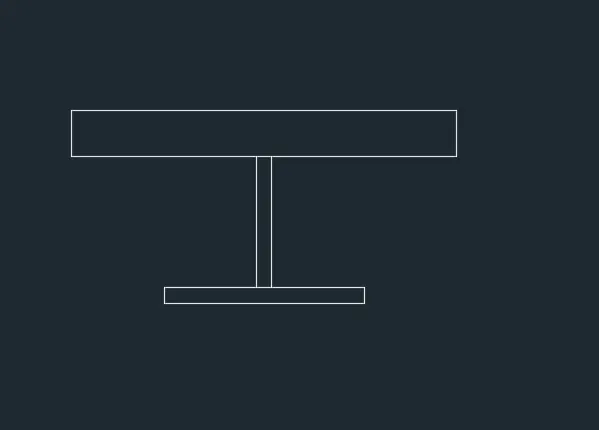
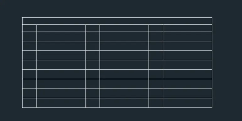
- Select the rectangle tool and specify the start point @800,380
- Sepecify the offset distance of 30
- Trim and erase the unwanted lines
STEP 24
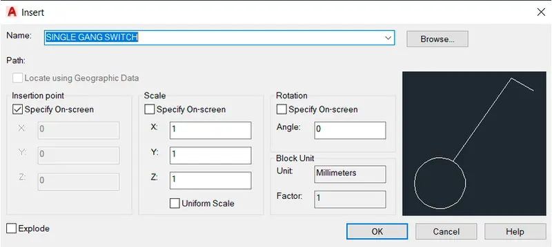
- Enter "i" command and insert the dialogbox by one by one which we created above
- Enter 'MTEXT' and start point of text as required
- Copy text box to wherever necessary
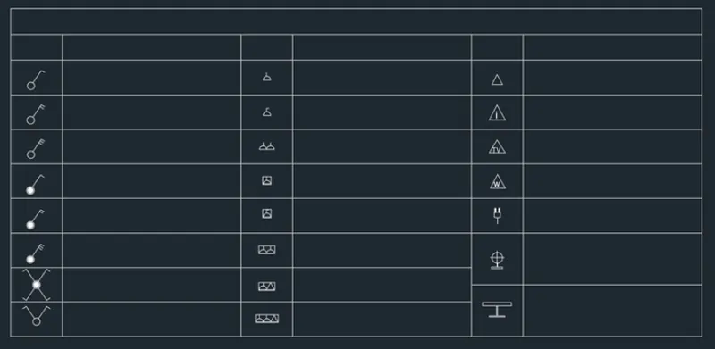
FINAL RESULT
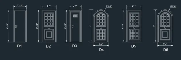
Q.4 Creating door types for residential building as a block in Auto cad
Ans. D1
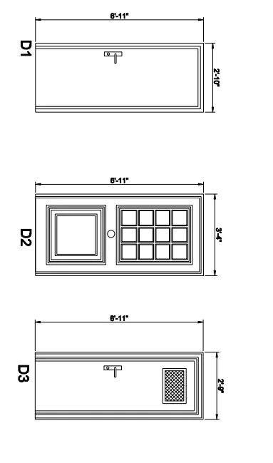
AIM: To create each door types for resisdential building as a block using AUto cad
Introduction:- The doors are created in AutoCad using Rectangle,Circle and line tools.
Procedure:-
D1
STEP 1
- Open Auto cad and set UNITS
- Select the Rectangle tool by entering 'REC' command tab
- Specify the start point ,enter @2'10", 6'11"
- Specify the offset distance of 2" and then offset the three sides of the smaller inner rectangle
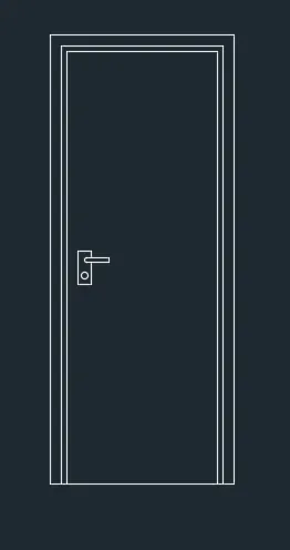
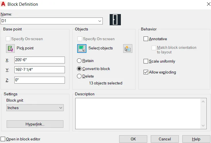
- Enter the 'B' in the command promt.
- In the Block Definition dialogue box, type in the name of the block as D1,pick the bottom right corner of the door ,select the object created and press Enter
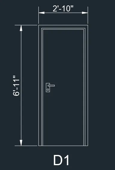
STEP 2
- Select the Dimension tool by entering 'DIM' in command promt
- Select first point and second point of object to be measured
- Enter 'MTEXT' command
- Specify the start point of text required
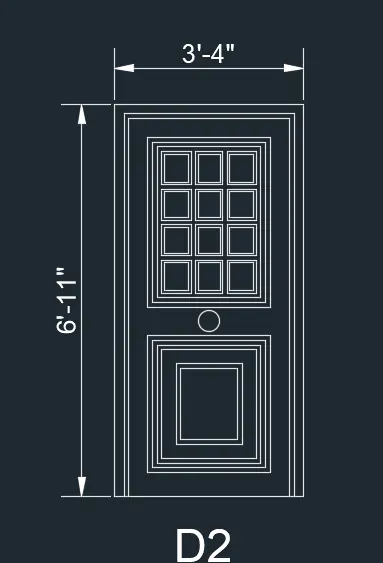
D2
STEP 1
- Select the rectangle tool
- Specify the start point, enter @3'4" , 6'11"
- Select the offset tool by entering 'O' in command tab
- Specify an offset distance of 2"
- Repeat offset distance as 1"
- Use offset the lines to create the pattern
- Select the trim and erase command to erase unwanted lines
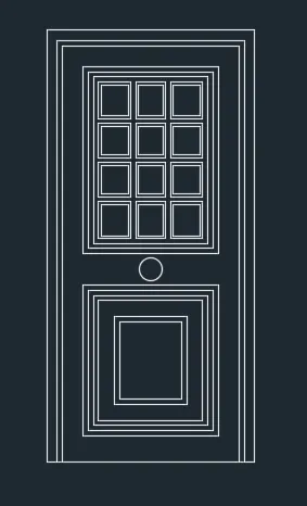
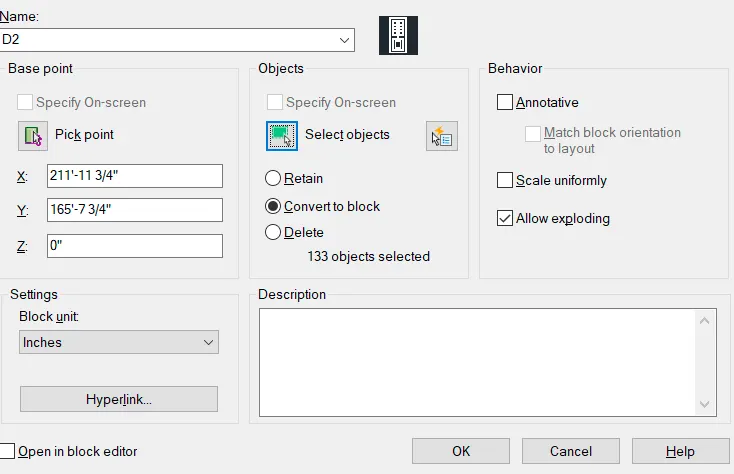
- Enter the 'B' in the command promt.
- In the Block Definition dialogue box, type in the name of the block as D2,pick the bottom right corner of the door ,select the object created and press Enter
STEP 2
- Select the Dimension tool by entering 'DIM' in command promt
- Select first point and second point of object to be measured
- Enter 'MTEXT' command
- Specify the start point of text required
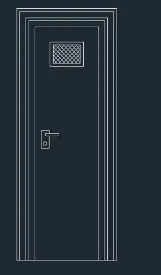
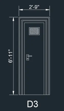
D3
STEP 1
- Select the rectangle tool
- Specify the start point, enter @2'9" , 6'11"
- Select the offset tool by entering 'O' in command tab
- Specify an offset distance of 2"
- Repeat offset distance as 1"
- Use offset the lines to create the pattern
- Select the trim and erase command to erase unwanted lines
- Enter the 'B' in the command promt.
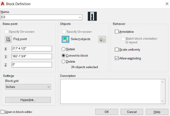
- In the Block Definition dialogue box, type in the name of the block as D3,pick the bottom right corner of the door ,select the object created and press Enter
STEP 2
- Select the Dimension tool by entering 'DIM' in command promt
- Select first point and second point of object to be measured
- Enter 'MTEXT' command
- Specify the start point of text required
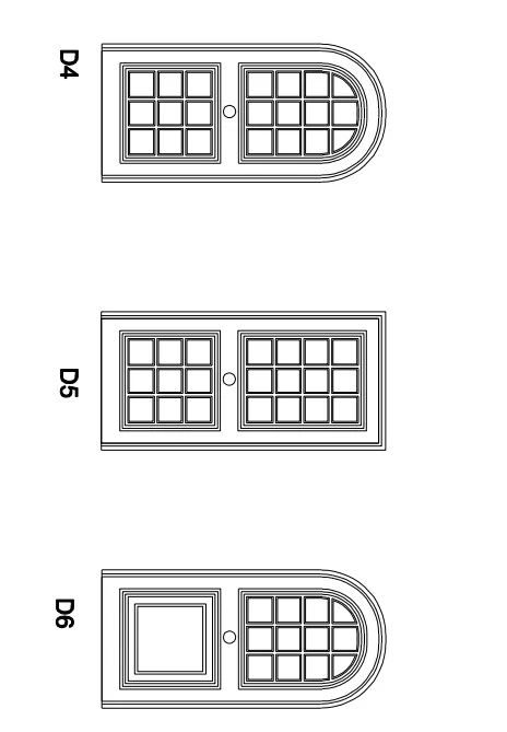
D4
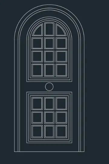
STEP 1
- Select the rectangle tool
- Specify the start point, enter @3'4" , 7'
- Select the offset tool by entering 'O' in command tab
- Specify an offset distance of 2"
- Repeat offset distance as 1"
- Use offset the lines to create the pattern
- Draw the door handle
- Select the ARC tool from Ribbon ,select the Start ,End and Direction option and draw an arc at the top of the door
- Select the trim and erase command to erase unwanted lines
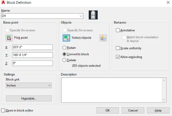
- Enter the 'B' in the command promt.
- In the Block Definition dialogue box, type in the name of the block as D4,pick the bottom right corner of the door ,select the object created and press Enter
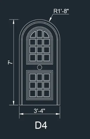
STEP 2
- Select the Dimension tool by entering 'DIM' in command promt
- Select first point and second point of object to be measured
- Enter 'MTEXT' command
- Specify the start point of text required
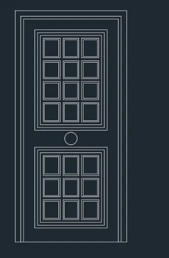
D5
STEP 1
- Select the rectangle tool
- Specify the start point, enter @3'4" , 6'11"
- Select the offset tool by entering 'O' in command tab
- Specify an offset distance of 2"
- Repeat offset distance as 1"
- Use offset the lines to create the pattern
- Select the trim and erase command to erase unwanted lines
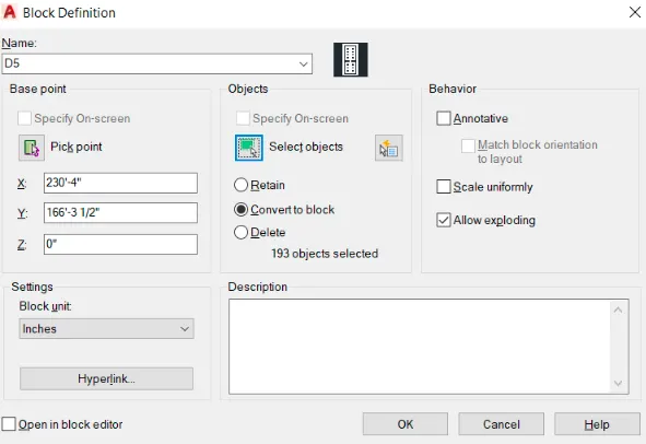
- Enter the 'B' in the command promt.
- In the Block Definition dialogue box, type in the name of the block as D5,pick the bottom right corner of the door ,select the object created and press Enter
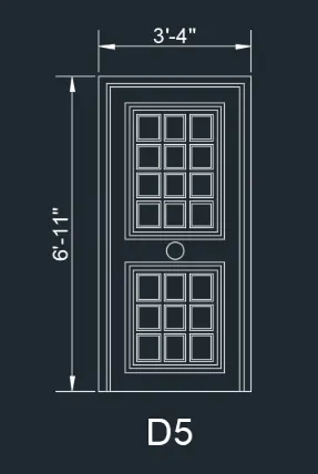
STEP 2
- Select the Dimension tool by entering 'DIM' in command promt
- Select first point and second point of object to be measured
- Enter 'MTEXT' command
- Specify the start point of text required
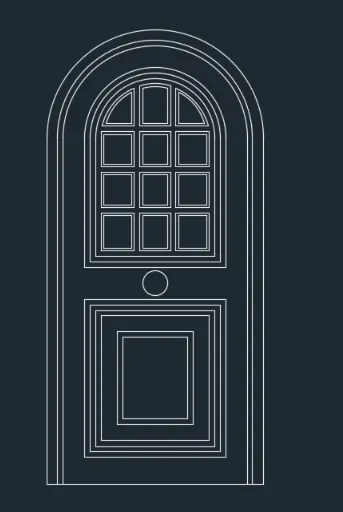
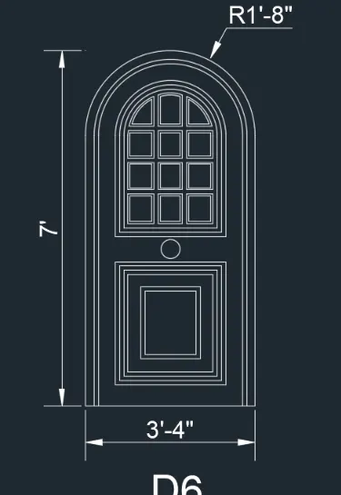
D6
STEP 1
- Select the rectangle tool
- Specify the start point, enter @2'9" , 6'11"
- Select the offset tool by entering 'O' in command tab
- Specify an offset distance of 2"
- Repeat offset distance as 1"
- Use offset the lines to create the pattern
- Select the ARC tool from Ribbon ,select the Start ,End and Direction option and draw an arc at the top of the door
- Select the trim and erase command to erase unwanted lines
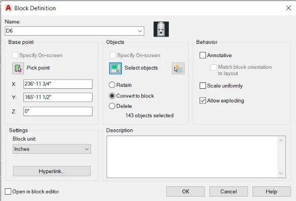
- Enter the 'B' in the command promt.
- In the Block Definition dialogue box, type in the name of the block as D6,pick the bottom right corner of the door ,select the object created and press Enter
STEP 2
- Select the Dimension tool by entering 'DIM' in command promt
- Select first point and second point of object to be measured
- Enter 'MTEXT' command
- Specify the start point of text required
FINAL RESULT
Q.5
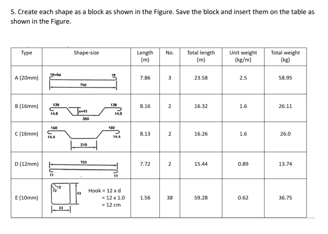
Ans. To create each bar as a block and inserting them on the table a shown in the figure in Autocad
Introduction:- The bar details are created using Rectangle and line tools
Procedure:-
step 1
- Open the Auto Cad
- Enter the UNITS and LIMITS
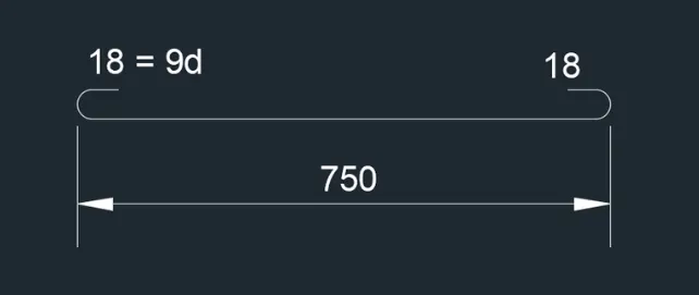
- Select the line command length of 750
- Select the ARC tool from Ribbon ,select the Start ,End and Direction option and draw an arc on both end of line
- Select Dimension tool and measure the required length
- Enter MTEXT command in command line
- Specify the start point of text required
- Enter the 'B' in the command promt.
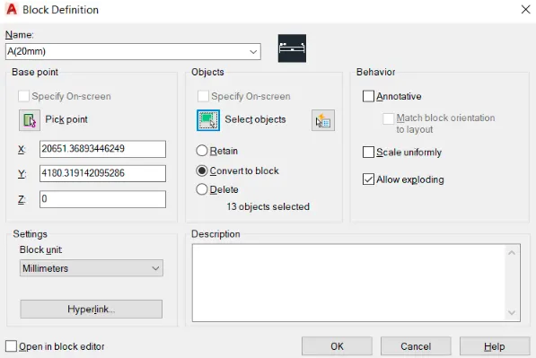
- In the Block Definition dialogue box, type in the name of the block as A(20mm),pick the bottom right corner of the door ,select the object created and press Enter
Step 2
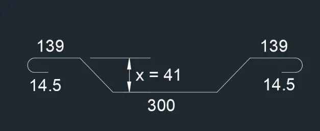
- Select the line command length of 300
- Select the ARC tool from Ribbon ,select the Start ,End and Direction option and draw an arc on both end of line
- Select Dimension tool and measure the required length
- Enter MTEXT command in command line
- Specify the start point of text required
- Enter the 'B' in the command promt.
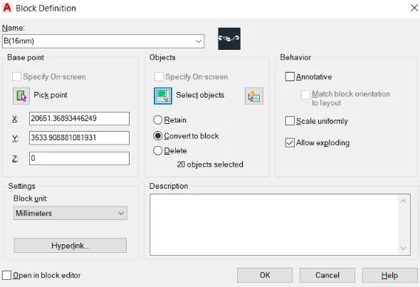
- In the Block Definition dialogue box, type in the name of the block as B(16mm),pick the bottom right corner of the door ,select the object created and press Enter
Step 3
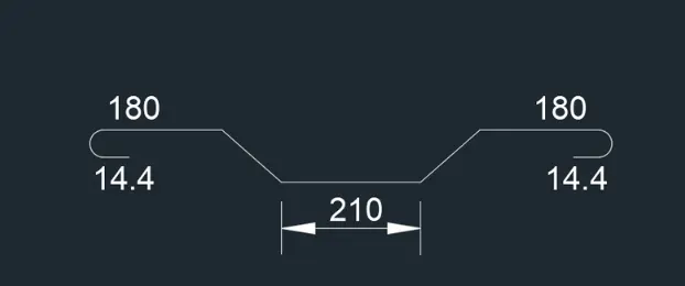
- Select the line command length of 210
- Select the ARC tool from Ribbon ,select the Start ,End and Direction option and draw an arc on both end of line
- Select Dimension tool and measure the required length
- Enter MTEXT command in command line
- Specify the start point of text required
- Enter the 'B' in the command promt.
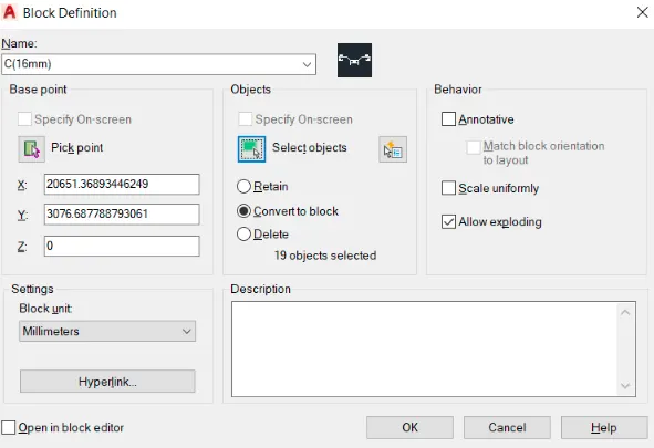
- In the Block Definition dialogue box, type in the name of the block as C(16mm),pick the bottom right corner of the door ,select the object created and press Enter
step 4
- Open the Auto Cad
- Enter the UNITS and LIMITS
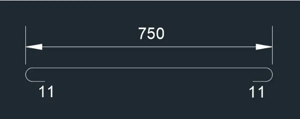
- Select the line command length of 750
- Select the ARC tool from Ribbon ,select the Start ,End and Direction option and draw an arc on both end of line
- Select Dimension tool and measure the required length
- Enter MTEXT command in command line
- Specify the start point of text required
- Enter the 'B' in the command promt.
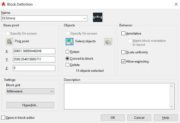
- In the Block Definition dialogue box, type in the name of the block as D(12mm),pick the bottom right corner of the door ,select the object created and press Enter
Step 5
- Select the rectangle tool
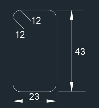
- Specify the start point, enter @230,430
- Draw the hook by the line command length of 12cm
- Select the ARC tool from Ribbon ,select the Start ,End and Direction option and draw an arc on both end of line
- Select Dimension tool and measure the required length
- Enter MTEXT command in command line
- Specify the start point of text required
- Enter the 'B' in the command promt.
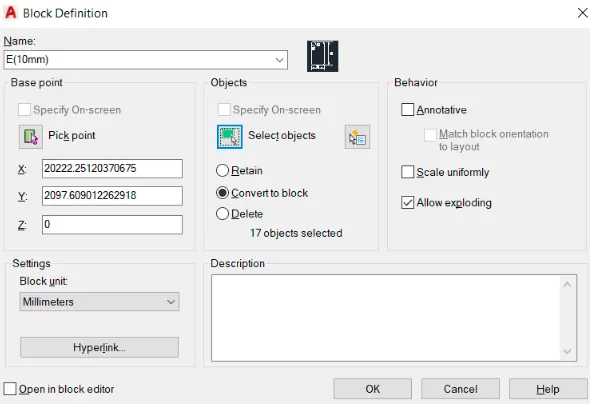
- In the Block Definition dialogue box, type in the name of the block as E(10mm),pick the bottom right corner of the door ,select the object created and press Enter
Step 6
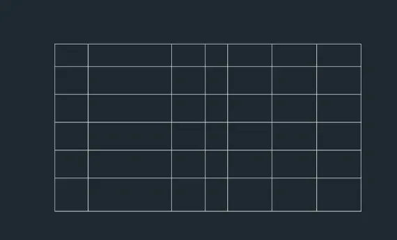
- Select the rectangle tool
- Specify the start point, enter @5500, 3000
- Select the offset tool by entering 'O' in command tab
- Specify an offset distance of 400
- Repeat offset specify distance as 500
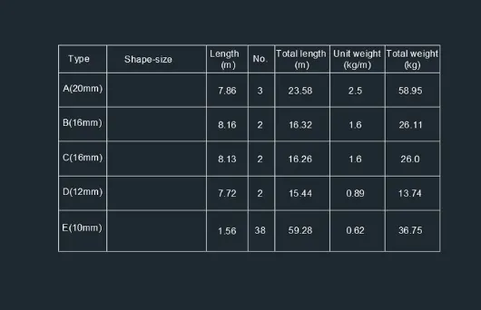
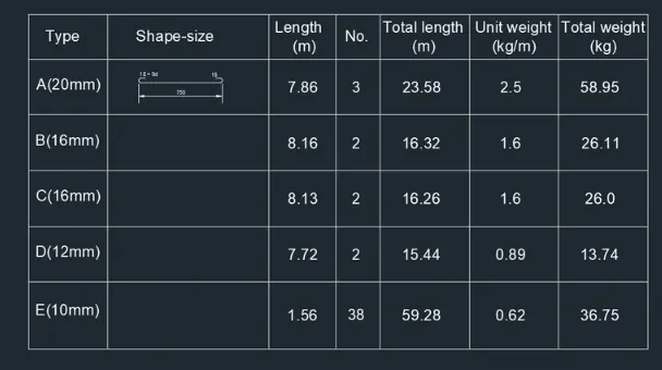
- Similarly by repeating above process create the table as shown in fig.
- Enter MTEXT command in command line
- Specify the start point of text required
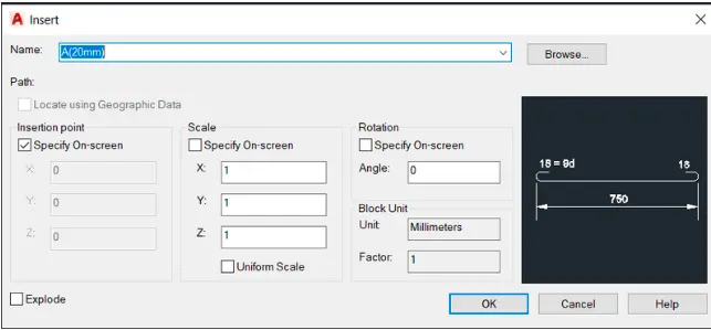
- Enter the 'i' in the command promt.
- In the dialogue box, select created symbol and insert them into Bar Bending Schedule table
FINAL RESULT