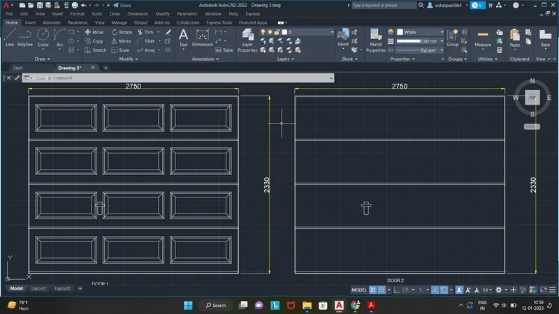
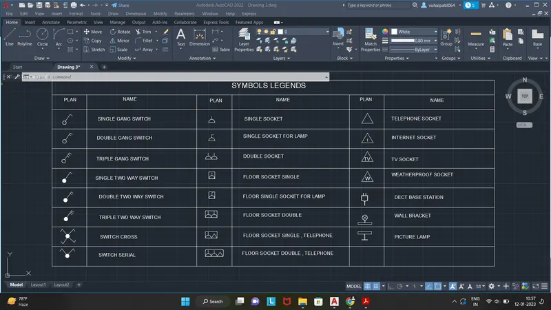
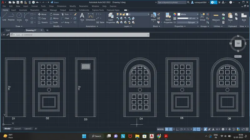
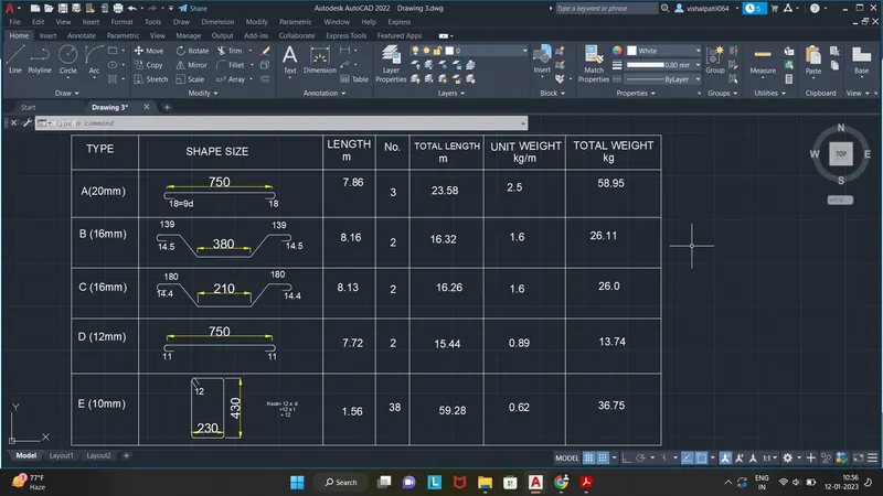
Creating Bar Bending schedule, Different Door types, and Creation of standard drawing templates using AutoCad
AIM- To Create the Legend details, doors elevation and bar bending schedule from given drawings using proper dimension techniques and dimension styles to document the project and assuming the sizes of the doors and windows as per construction standards.
INTRODUCTION- From the reference of the given attached document,Drawing the autocad Drawing in similar manner by considering industry standard dimensions for creating this report.
PROCEDURE-
- first create new file, set units in mm , dim-style and limit as per suitability of planned drawing to be draw in autocad.
- Since there was no clear distances were mentioned in drawing and many assumption were to be done with respect to construction practices or standards.
- Calculate the distances of wall to wall and check in section for references and if any dimensions are omitted than, missing data is taken out and along with wall dimensions column distances are also found out.
- Than using coordinate system draw line along width and length of plan and then creating a mirror along diagonal create a rectangular plot.
- using Array some block within doors are set with appropriate spacing.
- Again, using the TRIM lines for door locations, with reference doc.
- Using DTEXT command specifying text height to -1.5 and justifying it to left. Labelling to doors.
- Similarly using window block of respective dimension are placed using MOVE and COPY tools following to Using DTEXT command specifying text height to -1.5 and justifying it to left. Labelling to windows.
- Again using DTEXT tool keeping all text reference mentioned above used for labelling the rooms as per given in Drawing.
- Using DIMLINEAR tool dimension of each room are shown. In this way plan view is completed
- Proceeding to Section A-A then initially a copy of plan is taken out than , using Dot line section line is drawn with in the plan .
- Next using the TRIM option , trimming the portion of plan and limiting plan view up to Dot line.
- Later using XLINE horizontal a refence line is drawn which will at distance of height of building in elevation .
- Later all line of wall are projected towards the horizontal line using EXTEND command.
- Using beam and column dimension from table are drawn at respective location From visible section A-A.
- Next using the TRIM option , trimming the portion of plan and limiting plan view up to Dot line.
- Later using XLINE horizontal a refence line is drawn which will at distance of height of building in elevation .
- Later all line of wall are projected towards the horizontal line using EXTEND command,
- Using the dimensional references from the plan view for stairs are drawn using POLYLINE later HACTHED with solid colour.
- DIMLINEAR is used for showing the dimension.
RESULTS – This exercise provides to create legends for Drawing sheets with various details described into it, creating Door's blocks as per specified dimensions and schedule for bar bending table -which provides information about different bars that are to be used at exceution.