Creating Bar Bending schedule, Different Door types, and Creation of standard drawing templates using AutoCad
Aim : Creating Bar Bending schedule, Different Door types, and Creation of standard drawing templates using AutoCad
Introduction :
- Open autocad application
- Type Qnew and open new drawing
- Set units according to drawing
- Switch on object snap and object snap modes : Endpoint, Midpoint, Center, Nearest, Intersection, Perpendicular and Node
- Ortho mode is ON
Problem 1
Aim : To create two templates using Autocad
Procedure:
- Set units to decimal, precision zero and units to scale as "mm"
- Procedure for dimensions setting : Enter command dimstyle
Click on new and create a new style "STYLE 1"
1. Now go to Lines section and set the following:
Color, linetype and lineweight remians "ByBlock"
Extend beyong dimlines as 0.18
Offset from origin as 0.063
2. Next go to symbols and arrow section and set the following:
Arrow size 2
3. Next go to Text and set the following:
Text style : Standard : Font style - Arial, Font name regular
Text color : Byblock
Text height : 20
Text placement both vertical and horizontal as centered, View direction as left to right
Offset from dimline : 1
Text aligment : Aligned with dimension
4. Next go to Fit and set the following:
Use overall scale of 1
5. Next go to Primary units and set the following:
Unit format : Decimal
Precision : 0
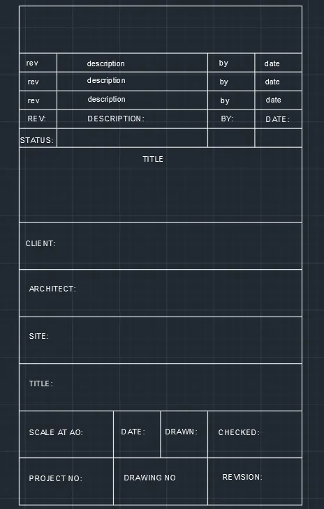
TEMPLATE 1
- Now draw a rectangle of size 1500 x 2650mm using line tool.
- Take offset of horizontal line of rectangle (at top) to a distance 250mm and there continue creating 5 horizontal lines using off set at a distance 100mm, 1 horizontal line at a distance 400mm and 5 horizontal lines at a distance 250mm.
- Draw three vertical lines perpendicular to first five lines ata distance 200mm, 300mm, 250mm
- Similarly draw two vertical lines perpendicular to last two lines at a distance 500mm, 500mm
- Draw a vertical line of 200mm lenth at a distance 750mm from left
- Now enter "ATTDEF" in the command box and enter following details in attribute definition tab
TAG : 1
PROMPT : WHAT IS REV?
DEFAULT : REV
(All attribute has Text style : standard, Text height : 30 and Justification : left
and text resulted is placed accordingly to given diagram) - Similary create following attributes
TAG : 2
PROMPT : WHAT IS DESCRIPTION?
DEFAULT : DESCRIPTION
TAG : 3
PROMPT : WHAT IS THE DATE?
DEFAULT : DATE
TAG : 4
PROMPT : WHAT IS STATUS?
DEFAULT : STATUS:
TAG : 5
PROMPT : WHAT IS TITLE?
DEFAULT : TITLE
TAG : 6
PROMPT : WHAT IS CLIENT?
DEFAULT : CLIENT:
TAG : 7
PROMPT : WHAT IS ARCHITECT?
DEFAULT : ARCHITECT:
TAG : 8
PROMPT : WHAT IS SITE?
DEFAULT : SITE:
TAG : 9
PROMPT : WHAT IS TITLE?
DEFAULT : TITLE
TAG : 10
PROMPT : WHAT IS SCALE AT AO?
DEFAULT : SCALE AT AO:
TAG : 11
PROMPT : WHAT IS THE DATE?
DEFAULT : DATE
TAG : 12
PROMPT : DRAWN BY?
DEFAULT : DRAWN:
TAG : 13
PROMPT : CHECKED OR NOT?
DEFAULT : CHECKED:
TAG : 14
PROMPT : WHAT IS PROJECT NO?
DEFAULT : PROJECT NO
TAG : 15
PROMPT : WHAT IS DRAWING_NO?
DEFAULT : DRAWING NO
TAG : 16
PROMPT : WHAT IS REVISION?
DEFAULT : REVISION - Now enter command "BLOCK" and enter name as "Custom1_titleblock
- Select "pick a point" option and pick a point on the table
- Now select objects table along with attributes and press okay
- Thus block is created
RESULT :
TEMPLATE 2
- Draw a rectangle 1 of size 2500 x 400mm using line tool.
- Draw vertical lines at a distance 700mm, 550mm, 350mm, 250mm, 650mm from left
- Draw a rectangle 2 of size 600 x 500mm above rectangle 1 using line tool
- Divide rectangle into 5parts horizontally and draw horizontal lines
- Draw vertical lines to the first four horizontal lines in the rectangle 2 at a distances 100mm, 350mm, 50mm, 100mm
- Now enter "ATTDEF" in the command box and enter following details in attribute definition tab
TAG : 1
PROMPT : WHAT IS SITE?
DEFAULT : SITE
Text style : standard, Text height : 30 and Justification : left
and text resulted is placed accordingly to given diagram
TAG : 2
PROMPT : NAME OF THE SITE
DEFAULT : SKILL LYNC
Text style : standard, Text height : 50 and Justification : left
and text resulted is placed accordingly to given diagram
TAG : 3
PROMPT : WHAT IS TITLE?
DEFAULT : TITLE
Text style : standard, Text height : 30 and Justification : left
and text resulted is placed accordingly to given diagram
TAG : 4
PROMPT : DESCRIPTION OF TITLE
DEFAULT : <TITLE>
Text style : standard, Text height : 50 and Justification : left
and text resulted is placed accordingly to given diagram
TAG : 5
PROMPT : WHAT IS PROJECT NO?
DEFAULT : PROJECT NO
Text style : standard, Text height : 30 and Justification : left
and text resulted is placed accordingly to given diagram
TAG : 6
PROMPT : WHAT IS DRAWING NO?
DEFAULT : DRAWING NO
Text style : standard, Text height : 30 and Justification : left
and text resulted is placed accordingly to given diagram
TAG : 7
PROMPT : WHAT IS THE DATE?
DEFAULT : DATE
Text style : standard, Text height : 30 and Justification : left
and text resulted is placed accordingly to given diagram
TAG : 8
PROMPT : WHAT IS THE NAME?
DEFAULT : NAME:
Text style : standard, Text height : 30 and Justification : left
and text resulted is placed accordingly to given diagram
TAG : 9
PROMPT : DRAWN BY?
DEFAULT : DRAWN:
Text style : standard, Text height : 20 and Justification : left
and text resulted is placed accordingly to given diagram
TAG : 10
PROMPT : CHECKED OR NOT?
DEFAULT : CHECKED:
Text style : standard, Text height : 20 and Justification : left
and text resulted is placed accordingly to given diagram
TAG : 11
PROMPT : WHAT IS REVISION?
DEFAULT : REVISION
Text style : standard, Text height : 30 and Justification : left
and text resulted is placed accordingly to given diagram
TAG : 12
PROMPT : WHAT IS REVISION?
DEFAULT : REVISIONText style : standard, Text height : 20 and Justification : left
and text resulted is placed accordingly to given diagram
TAG : 13
PROMPT : WHAT IS THE SCALE?
DEFAULT : SCALE A4
Text style : standard, Text height : 20 and Justification : left
and text resulted is placed accordingly to given diagram
TAG : 14
PROMPT : WHAT IS RF?
DEFAULT : 1:50
Text style : standard, Text height : 30 and Justification : left
and text resulted is placed accordingly to given diagram
TAG : 15
PROMPT : WHAT IS RF2?
DEFAULT : 1:100
Text style : standard, Text height : 30 and Justification : left
and text resulted is placed accordingly to given diagram
TAG : 16
PROMPT : WHAT IS ADDRESS?
DEFAULT : ADDRESS
Text style : standard, Text height : 30 and Justification : left
and text resulted is placed accordingly to given diagram
TAG : 17
PROMPT : WHAT IS REV?
DEFAULT : REV
Text style : standard, Text height : 20 and Justification : left
and text resulted is placed accordingly to given diagram
TAG : 18
PROMPT : WHAT IS DESCRIPTION?
DEFAULT : DESCRIPTION
Text style : standard, Text height : 20 and Justification : left
and text resulted is placed accordingly to given diagram
TAG : 19
PROMPT : WHAT IS BY?
DEFAULT : BY
Text style : standard, Text height : 20 and Justification : left
and text resulted is placed accordingly to given diagram
TAG : 20
PROMPT : WHAT IS THE DATE?
DEFAULT : DATE
Text style : standard, Text height : 20 and Justification : left
and text resulted is placed accordingly to given diagram
TAG : 21
PROMPT : WHAT IS AMENDMENT?
DEFAULT : AMENDMENT
Text style : standard, Text height : 30 and Justification : left
and text resulted is placed accordingly to given diagram
TAG : 23
PROMPT : WHAT IS A?
DEFAULT : A
Text style : standard, Text height : 20 and Justification : left
and text resulted is placed accordingly to given diagram
TAG : 24
PROMPT : WHAT IS B?
DEFAULT : B
Text style : standard, Text height : 20 and Justification : left
and text resulted is placed accordingly to given diagram
TAG : 25
PROMPT : WHAT IS C?
DEFAULT : C
Text style : standard, Text height : 20 and Justification : left
and text resulted is placed accordingly to given diagram
TAG : 26
PROMPT : WHAT IS THE YEAR?
DEFAULT : 2021
Text style : standard, Text height : 20 and Justification : left
and text resulted is placed accordingly to given diagram
TAG : 27
PROMPT : WHAT IS THE YEAR?
DEFAULT : 2020
Text style : standard, Text height : 20 and Justification : left
and text resulted is placed accordingly to given diagram
TAG : 28
PROMPT : WHAT IS THE YEAR?
DEFAULT : 2019
Text style : standard, Text height : 20 and Justification : left
and text resulted is placed accordingly to given diagram
Enter text symbol "<>" according to the digaram - Now enter command "BLOCK" and enter name as "Custom2_titleblock
- Select "pick a point" option and pick a point on the table
- Now select objects table along with attributes and press okay
- Thus block is created
RESULT :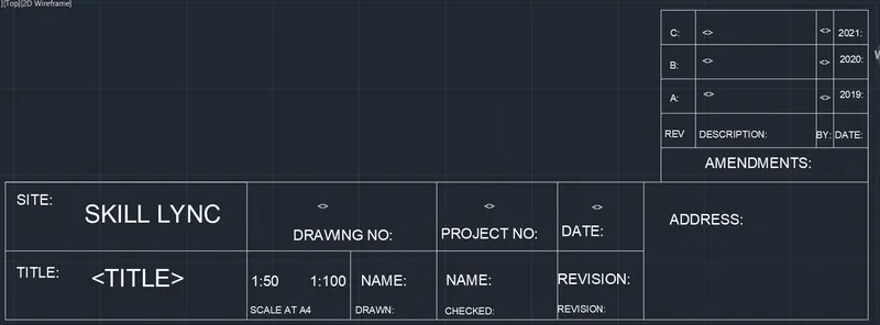
Problem 2:
AIM : To create the doors type for warehouse using Autocad
Procedure :
- Set units to decimal, precision zero and units to scale as "mm"
- Procedure for dimensions setting : Enter command dimstyle
Click on new and create a new style "STYLE 1"
1. Now go to Lines section and set the following:
Color, linetype and lineweight remians "ByBlock"
Extend beyong dimlines as 0.18
Offset from origin as 0.063
2. Next go to symbols and arrow section and set the following:
Arrow size 20
3. Next go to Text and set the following:
Text style : Standard : Font style - Arial, Font name regular
Text color : Byblock
Text height : 50
Text placement both vertical and horizontal as centered, View direction as left to right
Offset from dimline : 1
Text aligment : Horizontal
4. Next go to Fit and set the following:
Use overall scale of 1
5. Next go to Primary units and set the following:
Unit format : Decimal
Precision : 0
DOOR 1
- Draw a rectangle of size 2330 x 2750 using line tool
- Take offset of 75mm and create a rectangle
- Take offset of 25mm and create another rectangle
- Draw vertical lines inside above rectangle at distances 455, 500, 545, 1000, 1045, 1090, 1545, 1590, 1635 taken from left
- Draw Horizontal lines inside above rectangle at distances 25, 625, 975, 1575, 1925, 2525
- Draw a two rectangles perpendicular to each other as shown below
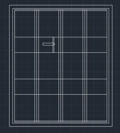
- Draw a rectangle of size 455 x 600
- Draw two more rectangle inside rectangle by take offset at a distance 25 and 75
- Now connect these rectangles diagonally as shown below
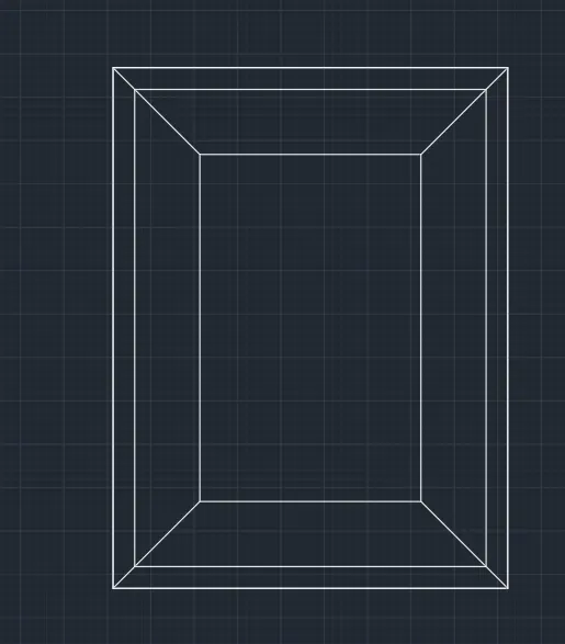
- Now enter command "BLOCK" and enter name as BLOCK
- Select "pick a point" option and pick a point on rectangle
- Now select object and press okay
- Thus block of this rectangular object is created
- Double click on this block to open block editor
- Go to parameter set and select linear array
- Specify start and end point
- Confirm the location of parameter
- Now go to actions and select array
- Select the parameter created
- Select the entire block
- Enter the distance as 545 and thus array for block is formed
- Save and close the block editor
- Place this block as shown below
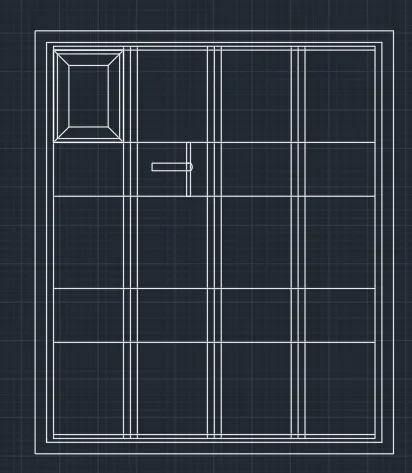
- Click on the block and press on arrow symbol and create 3 more block
- Using mirror tool 2 more row of blocks are created
- Trim off extra lines
- Now enter command "BLOCK" and enter name as DOOR1
- Select "pick a point" option and pick a point on door
- Now select all objects and press okay
- Thus block of entire door created
- Using dim linear mark the dimensions
- Draw a text DOOR1 with text height 100
RESULT :
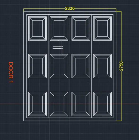
DOOR 2
- Draw a rectangle of size 2330 x 2750 using line tool
- Take offset of 75mm and create a rectangle
- Draw vertical lines inside above rectangle at distances 545, 1090, 1635 taken from left
- Draw a two rectangles perpendicular as drawn before
- Now enter command "BLOCK" and enter name as DOOR2
- Select "pick a point" option and pick a point on door
- Now select all objects and press okay
- Thus block of entire door created
- Using dim linear mark the dimensions
- Draw a text DOOR2 with text height 100
RESULT :
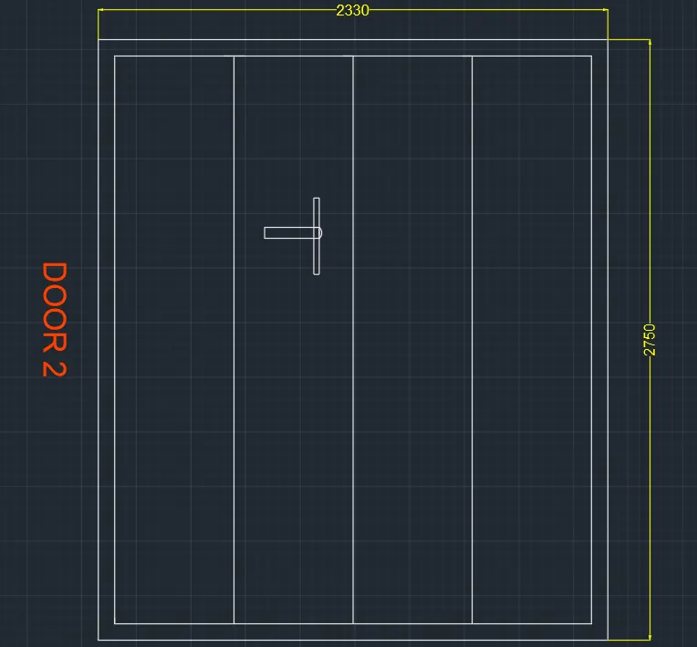
Problem 3:
Aim : To convert symbols into blocks and placing them in the legend using AutoCad
Procedure :
- Set units to decimal, precision zero and units to scale as "mm"
- Draw following diagrams
1. SINGLE GANG SWITCH
- Circle of radius 300mm is drawn and a line of length 700mm is drawn from centre at an angle 75 degree
- A 100 mm line (100<-15degree) is drawn at the end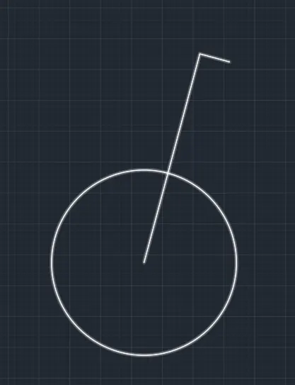
2. DOUBLE GANG SWITCH
- Circle of radius 300mm is drawn and a line of length 700mm is drawn from centre at an angle 75 degree
- A 100 mm line (100<-15degree) is drawn at the end
- 100mm line is drawn by taking offset 100mm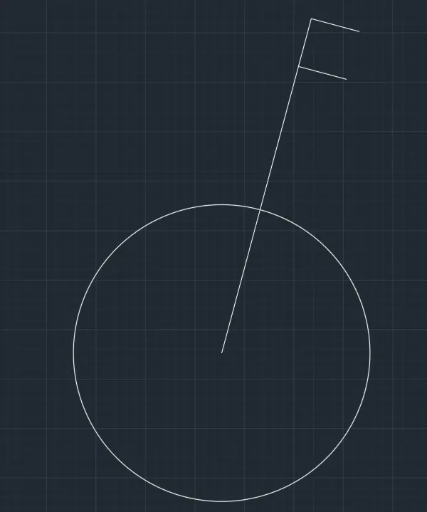
3. TRIPLE GANG SWITCH
- Circle of radius 300mm is drawn and a line of length 700mm is drawn from centre at an angle 75 degree
- A 100 mm line (100<-15degree) is drawn at the end
- Two 100mm line is drawn by taking offset 100mm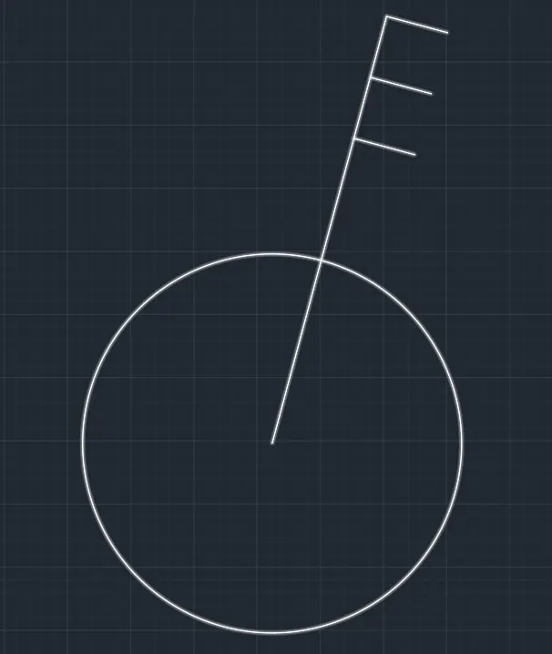
4. SINGLE TWO WAY SWITCH
- Circle of radius 300mm is drawn and a line of length 700mm is drawn from centre at an angle 75 degree
- A 100 mm line (100<-15degree) is drawn at the end
- Hatch the circle using solid hatch pattern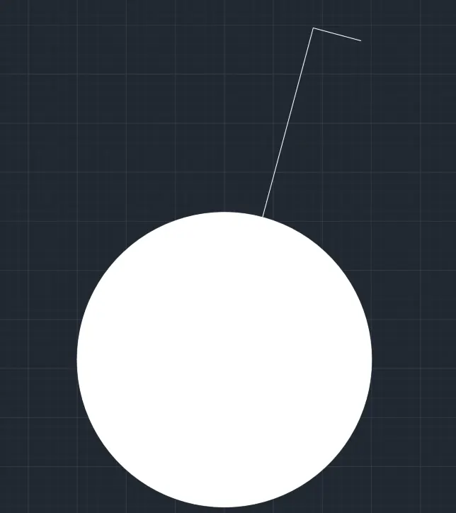
5. DOUBLE TWO WAY SWITCH
- Circle of radius 300mm is drawn and a line of length 700mm is drawn from centre at an angle 75 degree
- A 100 mm line (100<-15degree) is drawn at the end
- A 100mm line is drawn by taking offset 100mm
- Hatch the circle using solid hatch pattern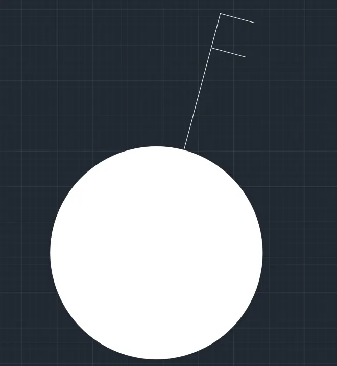
6. TRIPLE TWO WAY SWITCH
- Circle of radius 300mm is drawn and a line of length 700mm is drawn from centre at an angle 75 degree
- A 100 mm line (100<-15degree) is drawn at the end
- Two 100mm line is drawn by taking offset 100mm
- Hatch the circle using solid hatch pattern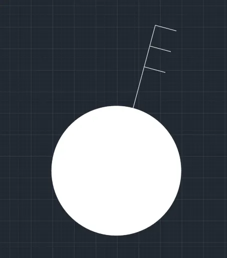
7. SWITCH CROSS
- Circle of radius 300mm is drawn and a line of length 700mm is drawn from centre at an angle 75 degree
- A 100 mm line (100<-15degree) is drawn at the end
- Mirror these two lines to left side and towards downward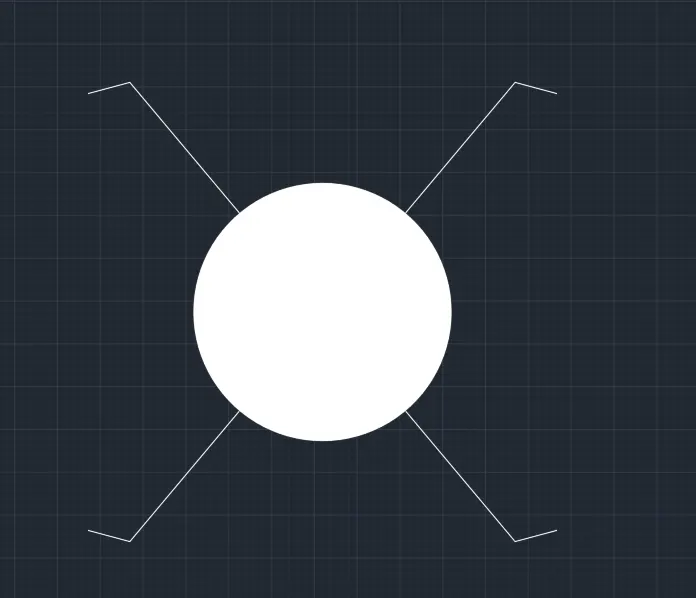
8. SWITCH SERIAL
- Circle of radius 300mm is drawn and a line of length 700mm is drawn from centre at an angle 75 degree
- A 100 mm line (100<-15degree) is drawn at the end
- Mirror these two lines to left side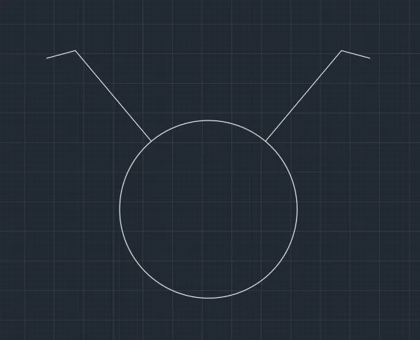
9. SINGLE SOCKET
- Draw a hemisphere with radius 300mm and draw a line of 100mm perpendicular to it
- Base line has line weight of 0.40mm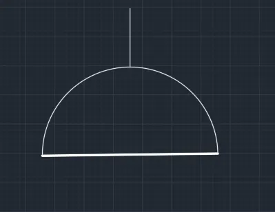
10. SINGLE SOCKET FOR LAMP
- Draw a hemisphere with radius 300mm and draw a line of 100mm perpendicular to it
- And then continue the line by drawing 100mm towards right
- Base line has line weight of 0.40mm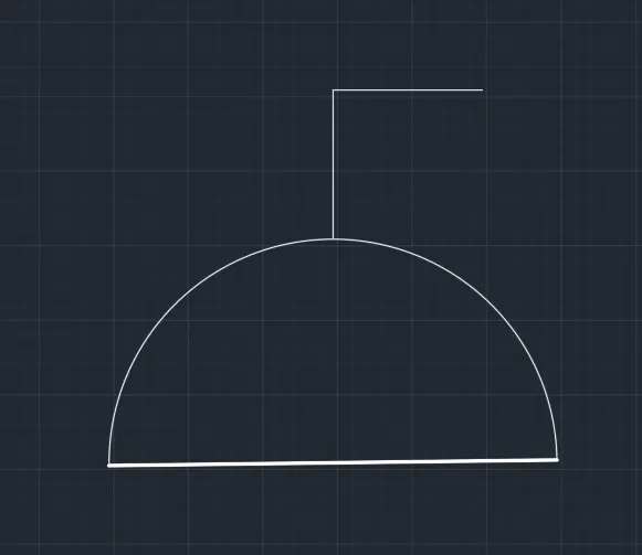
11. DOUBLE SOCKET
- Draw a two hemisphere with radius 300mm and draw a line of 100mm perpendicular to each
- Base line has line weight of 0.40mm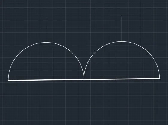
12. FLOOR SOCKET SINGLE
- Draw a hemisphere with radius 300mm and draw a line of 100mm perpendicular to it
- Base line has line weight of 0.40mm
- Draw lines of length 624mm around the hemisphere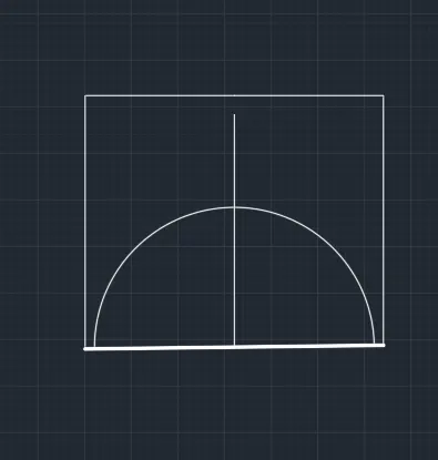
13. FLOOR SINGLE SOCKET FOR LAMP
- Draw a hemisphere with radius 300mm and draw a line of 100mm perpendicular to it
- And then continue the line by drawing 100mm towards right
- Base line has line weight of 0.40mm
- Draw lines of length 624mm around the hemisphere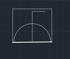
14. FLOOR SOCKET DOUBLE
- Draw a two hemisphere with radius 300mm and draw a line of 100mm perpendicular to it
- Base line has line weight of 0.40mm
- Draw lines of length 1224mm around the hemisphere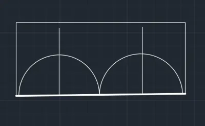
15. FLOOR SOCKET SINGLE TELEPHONE
- Draw a hemisphere with radius 300mm and draw a line of 100mm perpendicular to it
- And then draw a rectangle of height 400mm and base 600mm
- Base line has line weight of 0.40mm
- Draw lines of length 1224mm around the diagram
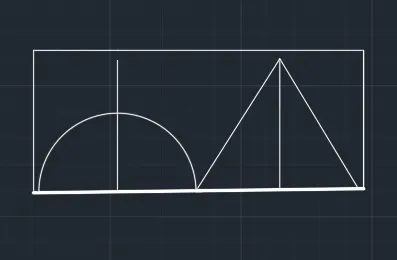
16. FLOOR SOCKET DOUBLE TELEPHONE
- Draw a two hemisphere with radius 300mm and draw a line of 100mm perpendicular to it
- And then draw a rectangle of height 400mm and base 600mm
- Base line has line weight of 0.40mm
- Draw lines of length 1824mm around the diagram
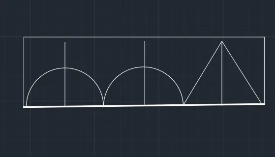
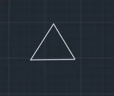
17. TELEPHONE SOCKET
- Draw a equilateral triangle
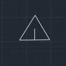
18. INTERNET SOCKET
- Draw a equilateral triangle and draw a line at base midpoint
19. TV SOCKET
- Draw a equilateral triangle and write a text "TV" inside it

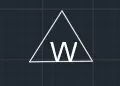
20. WEATHER PROOF SOCKET
- Draw a equilateral triangle and write a text "W" inside it
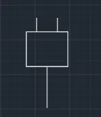
21. DECT BASE STATION
- Draw a rectangle 200 x 200 and draw lines two 50mm vertical lines perpendicular to it
- Draw a vertical line at midpoint of length 300mm
22. WALL BRACKET
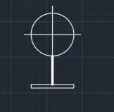
- Draw a circle of radius 600mm and draw cross lines to it
- Draw a vertical line 600 mm below circle perpendicularly with line weight 0.40 mm
- Draw a rectangle 200 x 20 mm
23. PICTURE LAMP
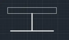
- Draw a rectangle 200 x 20 mm
- Draw a vertical line 50 mm below perpendicularly with line weight 0.40 mm
- And then draw a horizontal line of 200mm
- All these diagrams are converted to blocks using block command and names are given accordingly as shown below
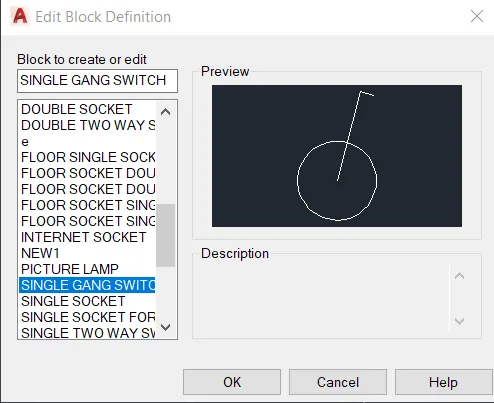
- Similarly name all blocks according to their names
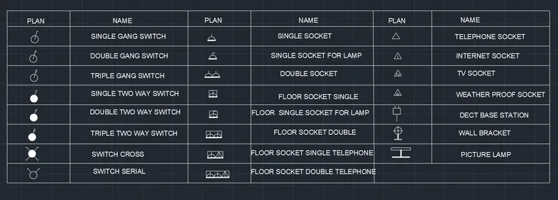
- Create a table with 6 columns and 9 rows
- In 2nd column write the names given below using text with height 200
SINGLE GANG SWITCH
DOUBLE GANG SWITCH
TRIPLE GANG SWITCH
SINGLE TWO WAY SWITCH
DOUBLE TWO WAY SWITCH
TRIPLE TWO WAY SWITCH
SWITCH CROSS
SWITCH SERIAL - In 4th column write the names given below using text with height 200
SINGLE SOCKET
SINGLE SOCKET FOR LAMP
DOUBLE SOCKET
FLOOR SOCKET SINGLE
FLOOR SOCKET SINGLE FOR LAMP
FLOOR SOCKET DOUBLE
FLOOR SOCKET SINGLE TELEPHONE
FLOOR DOUBLE SINGLE FOR LAMP - In 6th column write the names given below using text with height 200
TELEPHONE SOCKET
INTERNET SOCKET
TV SOCKET
WEATHER PROOF SOCKET
DECT BASE STATION
WALL BRACKET
PICTURE LAMP - Using insert command, insert blocks accordingly in the table under plan columns
RESULT :
Problem 4:
Aim : To create six doors and converting doors into blocks using Autocad
Procedure :
- Set units to engineering and units to scale as "inches"
- Procedure for dimensions setting : Enter command dimstyle
Click on new and create a new style "STYLE 1"
1. Now go to Lines section and set the following:
Color, linetype and lineweight remians "ByBlock"
Extend beyong dimlines as 0.18"
Offset from origin as 0.063"
2. Next go to symbols and arrow section and set the following:
Arrow size 3.68"
3. Next go to Text and set the following:
Text style : Standard : Font style - Arial, Font name regular
Text color : Byblock
Text height : 6.18"
Text placement both vertical and horizontal as centered, View direction as left to right
Offset from dimline : 1
Text aligment : Horizontal
4. Next go to Fit and set the following:
Use overall scale of 1
5. Next go to Primary units and set the following:
Unit format : Decimal
Precision : 0
DOOR 1
- Draw a rectangle of size 6'-11" x 2'-10" using line tool
- Take offset with distance 2" and draw lines on 3 sides
- Again take offset with distance 0.5" and draw lines on 3 sides
- Draw a door handle at a distance 4"
- Now enter command "BLOCK" and enter name as DOOR1
- Select "pick a point" option and pick a point on door
- Now select all objects and press okay
- Thus block of entire door created
- Using dim linear mark the dimensions
- Draw a text D1 with text height 3"
RESULT :

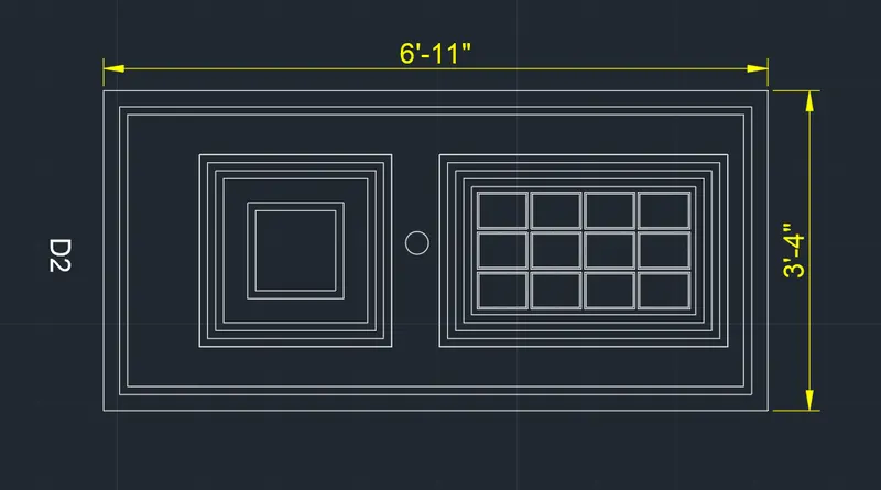
DOOR 2
- Draw a rectangle of size 6'-11" x 3'-4" using line tool
- Take offset of 2" and create a rectangle
- Take offset of 1" and create another rectangle
- Draw a rectangle of size 3' x 2' from a distance 2" as shown below
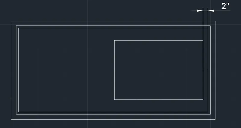
- Taking offset distance 1" create 4 more rectangle towards inside
- Taking offset distance 0.5" create 1 more rectangle towards inside
- Divide this rectangle into 4 columns and 3 rows which makes 12 rectangle
- In this 12 rectangles create 2 more rectangles each by taking offset distance 0.2" as shown below
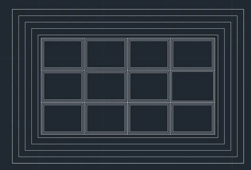
- Now remove outer most rectangle of these 12 rectangles which gives some space between each rectangle as shown below

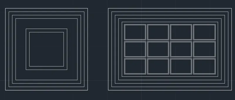
- Now a at distance 6" from above rectangles draw another rectangle of size 2' x 2' (towards left)
- Take offset of 1" and create 3 rectangles towards inside
- Take offset of 3" and create 1 rectangle towards inside
- Take offset of 1" and create 1 rectangle towards inside as shown below
- Draw a circle in between
- Now enter command "BLOCK" and enter name as DOOR2
- Select "pick a point" option and pick a point on door
- Now select all objects and press okay
- Thus block of entire door created
- Using dim linear mark the dimensions
- Draw a text D2 with text height 3"
RESULT :
DOOR 3
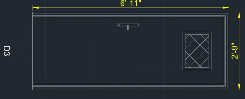
- Draw a rectangle of size 6'-11" x 2'-9" using line tool
- Take offset with distance 0.5" and draw a lines on 3 sides
- Take offset with distance 1" and draw lines on 3 sides towards inside
- Again take offset with distance 0.5" and draw 2 lines on 3 sides
- Draw a door handle at a distance 4"
- Draw a rectangle of size 1' x 1'-4" at a distance 4" from right side
- Take offset 1" and draw a rectangle towards inside
- Hatch this rectangle using hatch pattern ANS137 and hatch scale 1
- Now enter command "BLOCK" and enter name as DOOR3
- Select "pick a point" option and pick a point on door
- Now select all objects and press okay
- Thus block of entire door created
- Using dim linear mark the dimensions
- Draw a text D3 with text height 3"
RESULT :
DOOR 4
- Draw a rectangle of size 6'-11" x 3'-4" using line tool
- Take offset of 2" and draw a lines on 3 sides
- Take offset of 1" and draw a lines on 3 sides
- Draw a vertical line at a distance 1'-8" from right side and draw arcs as shown below
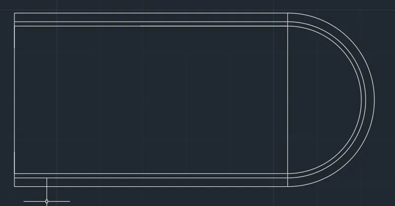
- Extra lines has been trimmed off
- Draw 2 horizontal lines at a distance 5" above and below which perpendicular to this vertical line
- Now draw a rectangle 2' x 2' at vertical line
- Taking offset distance 1" create 4 more rectangle towards inside
- Divide last rectangle into 4 columns and 3 rows which makes 12 rectangle
- In this 12 rectangles create 2 more rectangles each by taking offset distance 0.2"
- Now remove outer most rectangle of these 12 rectangles which gives some space between each rectangle
- Arcs are drawn as shown below
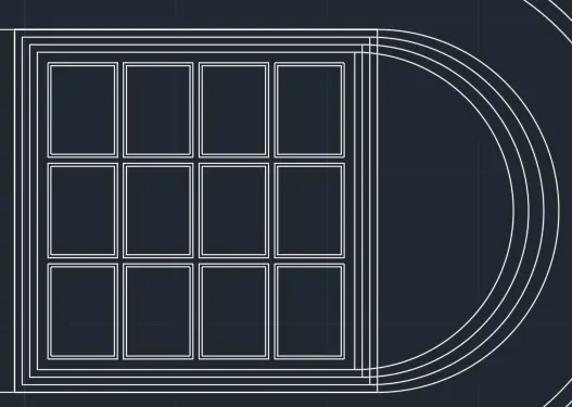
- Some adjustments are made by moving the objects towards right and trimmed off extra lines as shown below
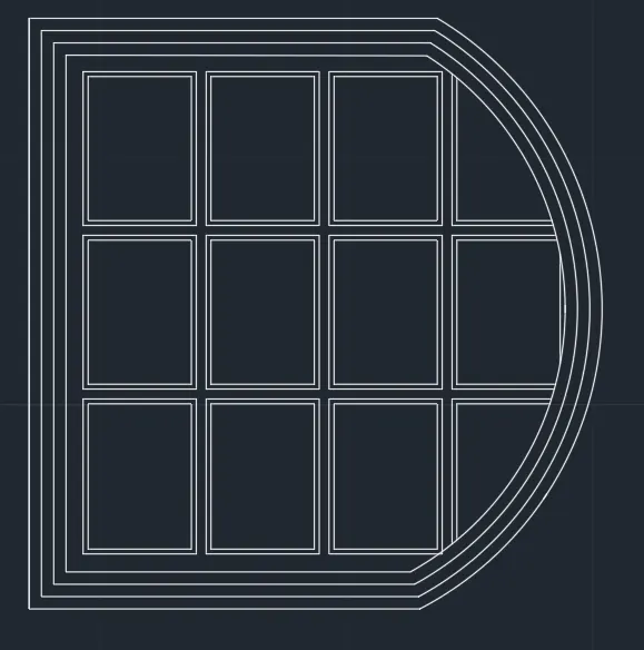
- Draw a rectangle of size 1'-4" x 2' at a distance 1'-4" from above rectangle
- Taking offset distance 0.5" create 3 more rectangle towards inside
- Taking offset distance 0.2" create 1 more rectangle
- Divide last rectangle into 3 columns and 3 rows which makes 9 rectangle
- In this 12 rectangles create 2 more rectangles each by taking offset distance 0.2"
- Now remove outer most rectangle of these 12 rectangles which gives some space between each rectangle
- Now enter command "BLOCK" and enter name as DOOR4
- Select "pick a point" option and pick a point on door
- Now select all objects and press okay
- Thus block of entire door created
- Using dim linear mark the dimensions
- Draw a text D4 with text height 3"
RESULT :
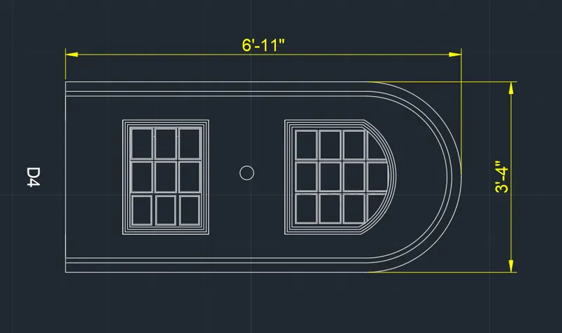
DOOR 5
- Draw a rectangle of size 6'-11" x 3'-4" using line tool
- Take offset of 2" and draw a lines on 3 sides
- Take offset of 1" and draw a lines on 3 sides
- Draw a rectangle of size 2' x 2' from a distance 9"
- Taking offset distance 0.5" create 5 more rectangle towards inside
- Divide last rectangle into 4 columns and 3 rows which makes 12 rectangle
- In this 12 rectangles create 2 more rectangles each by taking offset distance 0.2"
- Now remove outer most rectangle of these 12 rectangles which gives some space between each rectangle
- Draw a rectangle of size 1'-6" x 2' at a distance 1'-5" from above rectangle
- Taking offset distance 0.5" create 3 more rectangle towards inside
- Taking offset distance 0.2" create 1 more rectangle
- Divide last rectangle into 3 columns and 3 rows which makes 9 rectangle
- In this 12 rectangles create 2 more rectangles each by taking offset distance 0.2"
- Now remove outer most rectangle of these 12 rectangles which gives some space between each rectangle
- Draw a circle in between these rectangles
- Now enter command "BLOCK" and enter name as DOOR5
- Select "pick a point" option and pick a point on door
- Now select all objects and press okay
- Thus block of entire door created
- Using dim linear mark the dimensions
- Draw a text D5 with text height 3"
RESULT :
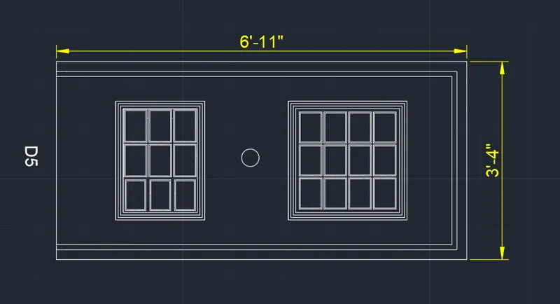
DOOR 6
- Draw a rectangle of size 6'-11" x 3'-4" using line tool
- Take offset of 2" and draw a lines on 3 sides
- Take offset of 1" and draw a lines on 3 sides
- Draw a vertical line at a distance 1'-8" from right side and draw arcs as shown below
- Extra lines has been trimmed off
- Draw 2 horizontal lines at a distance 5" above and below which perpendicular to this vertical line
- Now draw a rectangle 2' x 2' at vertical line
- Taking offset distance 1" create 4 more rectangle towards inside
- Divide last rectangle into 4 columns and 3 rows which makes 12 rectangle
- In this 12 rectangles create 2 more rectangles each by taking offset distance 0.2"
- Now remove outer most rectangle of these 12 rectangles which gives some space between each rectangle
- Arcs are drawn as shown below
- Some adjustments are made by moving the objects towards right and trimmed off extra lines as shown below
- Draw a circle in between
- Draw a rectangle of size 1'-6" x 2' at a distance 1'-4" from above rectangle
- Taking offset distance 0.5" create 3 more rectangle towards inside
- Taking offset distance 2" create a rectangle towards inside
- Taking offset distance 0.2" create a rectangle towards inside
- Now enter command "BLOCK" and enter name as DOOR6
- Select "pick a point" option and pick a point on door
- Now select all objects and press okay
- Thus block of entire door created
- Using dim linear mark the dimensions
- Draw a text D6 with text height 3
RESULT :
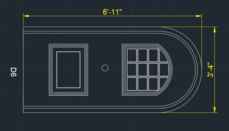
PROBLEM 5:
AIM : To create blocks and insert them in the table using AutoCad
PROCEDURE :
- Set units to decimal, precision zero and units to scale as "mm"
- Procedure for dimensions setting : Enter command dimstyle
Click on new and create a new style "STYLE 1"
1. Now go to Lines section and set the following:
Color, linetype and lineweight remians "ByBlock"
Extend beyong dimlines as 0.18
Offset from origin as 0.063
2. Next go to symbols and arrow section and set the following:
Arrow size 20
3. Next go to Text and set the following:
Text style : Standard : Font style - Arial, Font name regular
Text color : Byblock
Text height : 50
Text placement both vertical and horizontal as centered, View direction as left to right
Offset from dimline : 1
Text aligment : Horizontal
4. Next go to Fit and set the following:
Use overall scale of 1
5. Next go to Primary units and set the following:
Unit format : Decimal
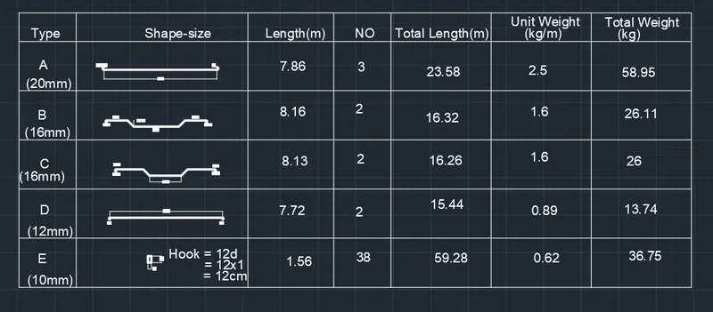
Precision : 0 - Draw a rectangle of with 7 columns and 6 rows
- Fill the table as given information below with text height 64 and text style standard
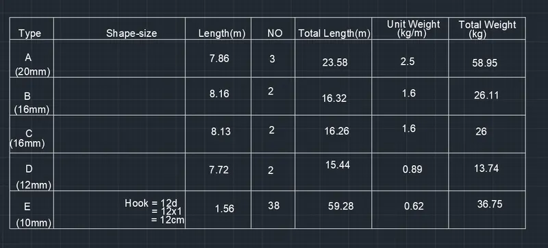
- Now a draw diagrams with dimension as shown below and take line weight as 0.40mm
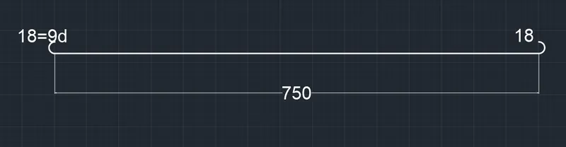
Above diagram is drawn by drawing a line of 750mm and drawing a circle of radius 18mm
Extra lines are trimmed off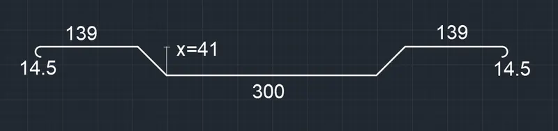
Above diagram is drawn by drawing a line of 300mm and then draw lines of 58mm with an angle 135 degree and 45 degree on both sides
Draw a horizontal line of 139mm on both sides
At the end draw a circle of radius 14.5
Extra lines are trimmed off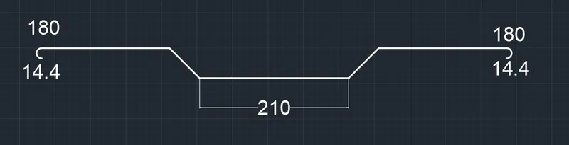
Above diagram is drawn by drawing a line of 210mm and then draw lines of 58mm with an angle 135 degree and 45 degree on both sides
Draw a horizontal line of 180mm on both sides
At the end draw a circle of radius 14.4
Extra lines are trimmed off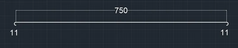
Above diagram is drawn by drawing a line of 750mm and drawing a circle of radius 11mm
Extra lines are trimmed off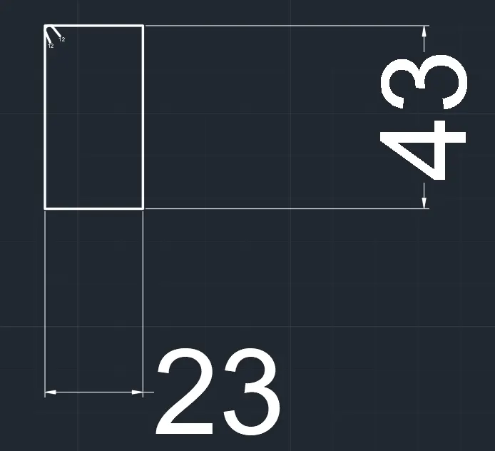
Above diagram is drawn by drawing a rectangle of size 23 x 43mm and draw stirrups of length 12mm - All these diagrams are converted into blocks and named it as
BlockA
BlockB
BlockC
BlockD
BlockE - These blocks are inserted in the table using insert command according to the given diagram
RESULT :