Creating Bar Bending schedule, Different Door types, and Creation of standard drawing templates using AutoCad
1) AIM
to draw the Title bock template and save it as block.
INTRODUCTION
This Titile block template is created using autocad and the procedure is explained in detail in each steps and the commands are used in this drawing are.
COMMANDS USED IN THIS DRAWING
- L- LINE
- F8- ORTHO MODE
- GRIDMODE
- F10 - POLAR TRACKING
- ST - STYLE TEXT
- DT-SINGLE TEXT
- T- MULTITEXT
- C- CIRCLE
- CO-COPY
- M-MOVE
- T- TEXT
- TR- TRIM
- O-OFFSET
- F- FILLET
- D-DIMENSION STYLE
- REC-RECTANGLE
- DIMLINEAR
- DIMCONT
- DIMBASE
- LEADER
- QLEADER
- SC-SCALE
- LA-layers
- ADC-design center
- B-Block
- I-insert
- Xl-xline
- H-hatch
PROCEDURE
- open autocad file in windows desktop.
- a dialog box will open it shows startup from scratch.
- click the radio button imperial to start the project.
- in command box type gridmode to show the gridmode by typing 1 in the command box
- type F8 to get ortho on.
- type limmax to set the maximum layout.
- type llmits to set the layout.
- TYPE UN FOR UNITS and set to decimal.
STEP 1
Type L-Line
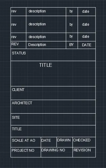
type l for line and draw the title block as shown in fig question 1
draw the title block template.
type t- multitext to text the title block as shown.
use the scale to enlarge and fits into paper drawing sheet.
type o - offset the lines whereever nesessary.
type co-copy the text as shown it easy to arrange and set.
as shown if fig custom_1titleblock and custom_1titleblock done

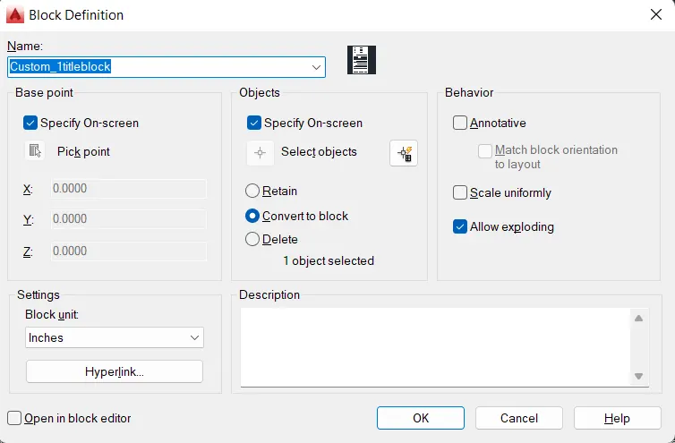
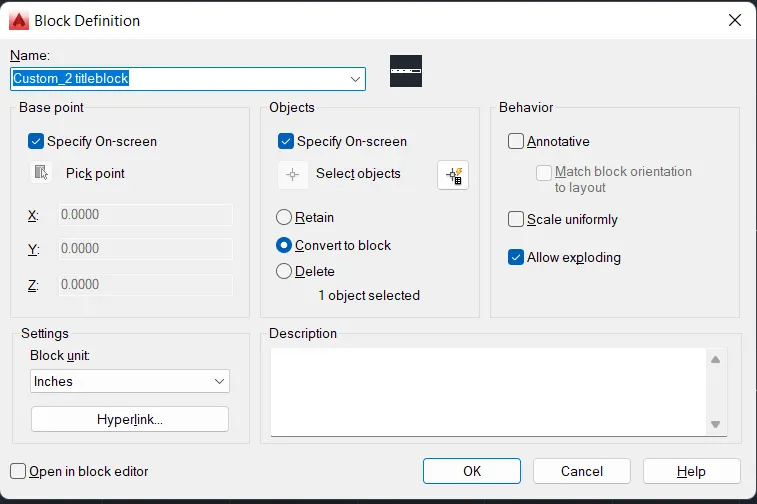
type B-block a dialog box open as shown in the fig below.
after drawn type B- block the title block as one object
select the insertion point of the object.
selct the object on the screen to set as a block
select the convert to block and the drawing will be converted to block.
press ok to convert into a block.
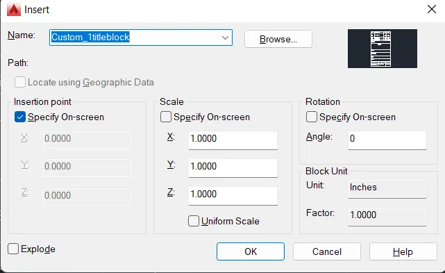
type I-insert the block in the drawing sheet as shown in the fig below.
select the custom_1 title block to insert into the drawing sheet.
select the insertion point to where we needed this block.
Result: The follwing Custuom_1titleblock is completed and converted to block.
2) AIM
to draw the door type as per given dimension and save it as block.
INTRODUCTION
This door type is created using autocad and the procedure is explained in detail in each steps and the commands are used in this drawing are.
COMMANDS USED IN THIS DRAWING
- L- LINE
- F8- ORTHO MODE
- GRIDMODE
- F10 - POLAR TRACKING
- ST - STYLE TEXT
- DT-SINGLE TEXT
- T- MULTITEXT
- C- CIRCLE
- CO-COPY
- M-MOVE
- T- TEXT
- TR- TRIM
- O-OFFSET
- F- FILLET
- D-DIMENSION STYLE
- REC-RECTANGLE
- DIMLINEAR
- DIMCONT
- DIMBASE
- LEADER
- QLEADER
- SC-SCALE
- LA-layers
- ADC-design center
- B-Block
- I-insert
- Xl-xline
- H-hatch
PROCEDURE
- open autocad file in windows desktop.
- a dialog box will open it shows startup from scratch.
- click the radio button imperial to start the project.
- in command box type gridmode to show the gridmode by typing 1 in the command box
- type F8 to get ortho on.
- type limmax to set the maximum layout.
- type llmits to set the layout.
- TYPE UN FOR UNITS and set to decimal.
STEP 1
Type L-Line
type l for line and draw the door as shown in fig question 2
type rec- rectangle to easly draw as shown in qusetion.
type d- dimension style to set the dimensions as per the door format,
type dimlinear-to align the dimension the door.
type dt- single text to text the doors in the center of the door.
type o- offset to offset the line as per the reqirement.
type B-block a dialog box open as shown in the fig below.
after drawn type B- block the title block as one object
select the insertion point of the object.
selct the object on the screen to set as a block
select the convert to block and the drawing will be converted to block.
press ok to convert into a block.
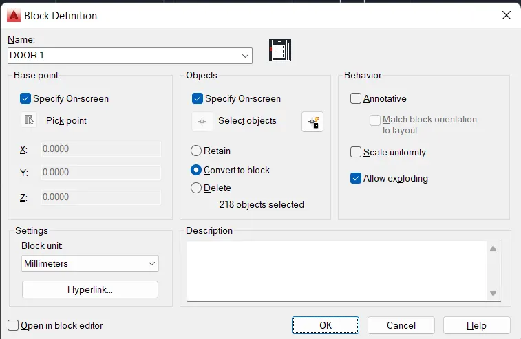
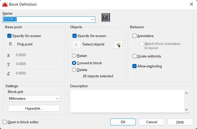
type I-insert the block in the drawing sheet as shown in the fig below.
select the custom_1 title block to insert into the drawing sheet.
select the insertion point to where we have to insert this block.
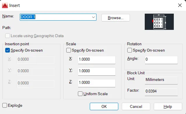
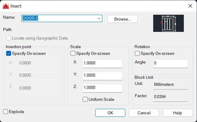
Result: The follwing door 1 & door 2 is completed and converted to block.
3)AIM
to draw the symbol legend and save it as block.
INTRODUCTION
This symbol legend is created using autocad and the procedure is explained in detail in each steps and the commands are used in this drawing are.
COMMANDS USED IN THIS DRAWING
- L- LINE
- F8- ORTHO MODE
- GRIDMODE
- F10 - POLAR TRACKING
- ST - STYLE TEXT
- DT-SINGLE TEXT
- T- MULTITEXT
- C- CIRCLE
- CO-COPY
- M-MOVE
- T- TEXT
- TR- TRIM
- O-OFFSET
- F- FILLET
- D-DIMENSION STYLE
- REC-RECTANGLE
- DIMLINEAR
- DIMCONT
- DIMBASE
- LEADER
- QLEADER
- SC-SCALE
- LA-layers
- ADC-design center
- B-Block
- I-insert
- Xl-xline
- H-hatch
PROCEDURE
- open autocad file in windows desktop.
- a dialog box will open it shows startup from scratch.
- click the radio button imperial to start the project.
- in command box type gridmode to show the gridmode by typing 1 in the command box
- type F8 to get ortho on.
- type limmax to set the maximum layout.
- type llmits to set the layout.
- TYPE UN FOR UNITS and set to decimal.
STEP 1
Type L-Line
type l for line and draw the symbol legend as shown in fig question 3
draw the switches as shown in legend as set as block.
draw the seperate switches and set a block as shown.
after drawn the switches in sperate block set the table as in block
in each drawing we can easily set the block into the drawing.
type o - offset the line as shown and seprate table is done using this.
type t-mulitiline text to text the switches.
type co- copy the text wherever needed.
after sepratiing each one as block complete this legend and set as block.
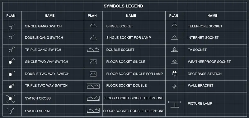
type B-block a dialog box open as shown in the fig below.
after drawn type B- block the title block as one object
select the insertion point of the object.
selct the object on the screen to set as a block
select the convert to block and the drawing will be converted to block.
press ok to convert into a block.
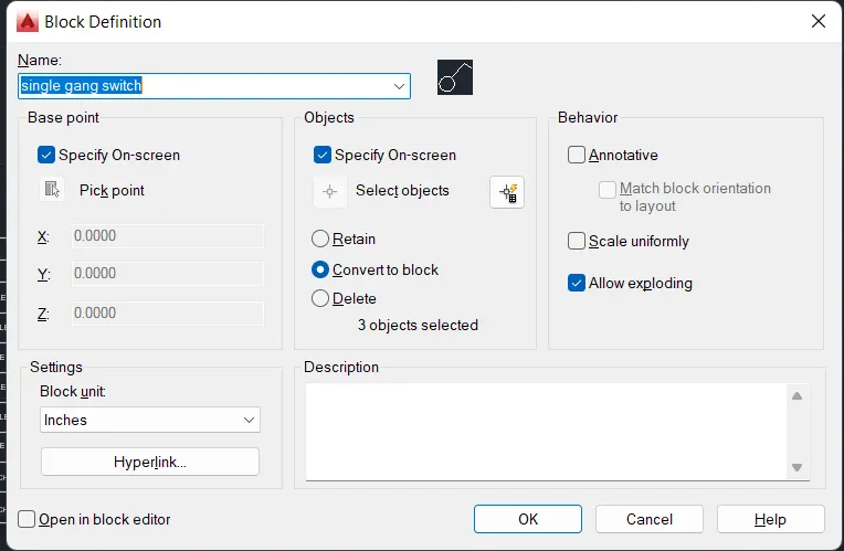
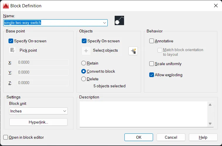
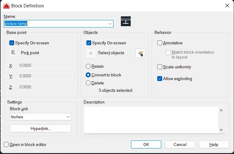
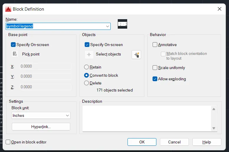
type I-insert the block in the drawing sheet as shown in the fig below.
select the custom_1 title block to insert into the drawing sheet.
select the insertion point to where we needed this block.
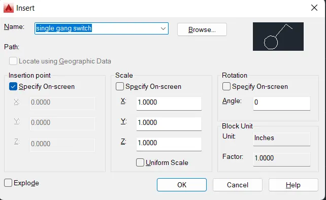
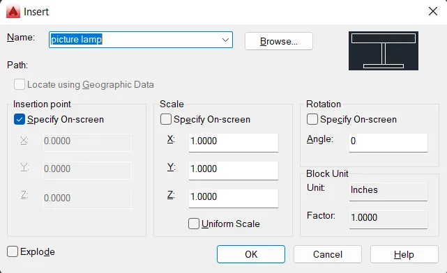
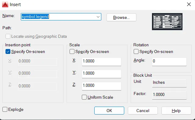
Result: The follwing symbol legend is completed and converted to block.
4)AIM
to draw the door type for residential building as per given dimension and save it as block.
INTRODUCTION
This door type for residential building is created using autocad and the procedure is explained in detail in each steps and the commands are used in this drawing are.
COMMANDS USED IN THIS DRAWING
- L- LINE
- F8- ORTHO MODE
- GRIDMODE
- F10 - POLAR TRACKING
- ST - STYLE TEXT
- DT-SINGLE TEXT
- T- MULTITEXT
- C- CIRCLE
- CO-COPY
- M-MOVE
- T- TEXT
- TR- TRIM
- O-OFFSET
- F- FILLET
- D-DIMENSION STYLE
- REC-RECTANGLE
- DIMLINEAR
- DIMCONT
- DIMBASE
- LEADER
- QLEADER
- SC-SCALE
- LA-layers
- ADC-design center
- B-Block
- I-insert
- Xl-xline
- H-hatch
PROCEDURE
- open autocad file in windows desktop.
- a dialog box will open it shows startup from scratch.
- click the radio button imperial to start the project.
- in command box type gridmode to show the gridmode by typing 1 in the command box
- type F8 to get ortho on.
- type limmax to set the maximum layout.
- type llmits to set the layout.
- TYPE UN FOR UNITS and set to engineering.
STEP 1
Type L-Line
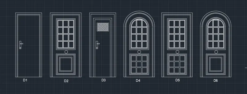
type l for line and draw the door as shown in fig question 4
type rec- rectangle to easly draw as shown in qusetion.
type d- dimension style to set the dimensions as per the door format,
type dimlinear-to align the dimension the door.
type dt- single text to text the doors in the center of the door.
type o- offset to offset the line as per the reqirement.
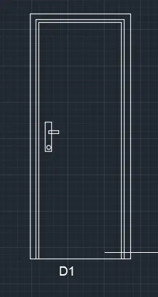
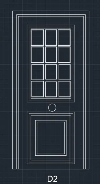
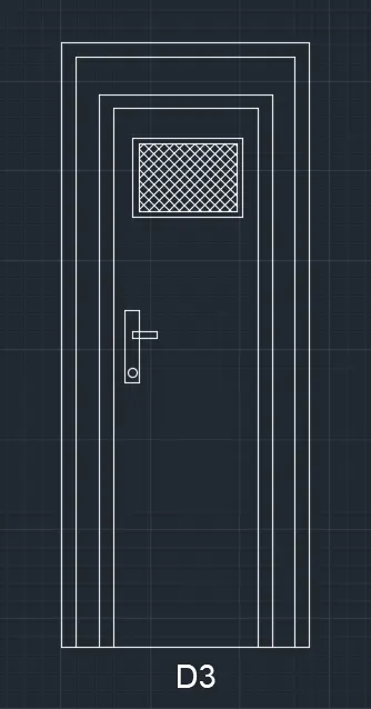
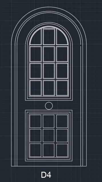
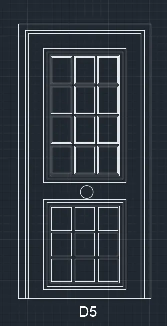
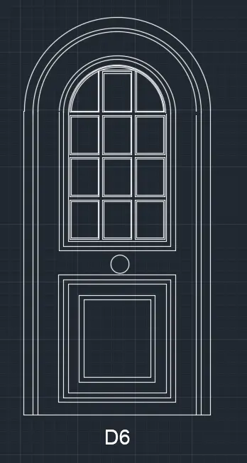
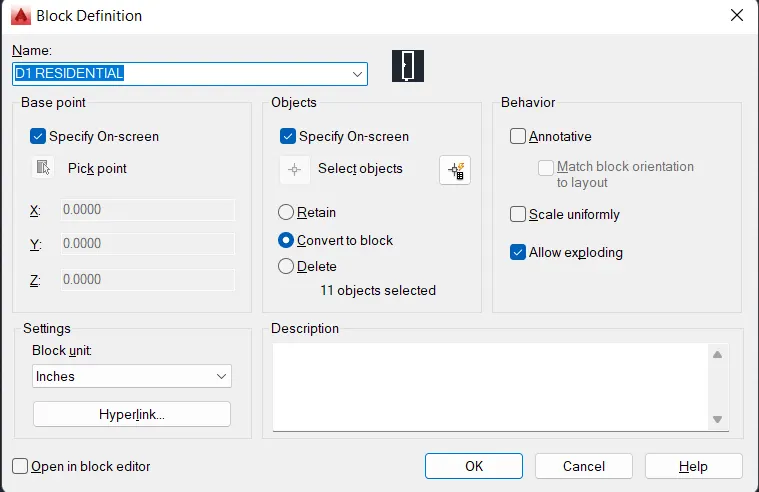
type B-block a dialog box open as shown in the fig below.
after drawn type B- block the title block as one object
select the insertion point of the object.
selct the object on the screen to set as a block
select the convert to block and the drawing will be converted to block.
press ok to convert into a block.
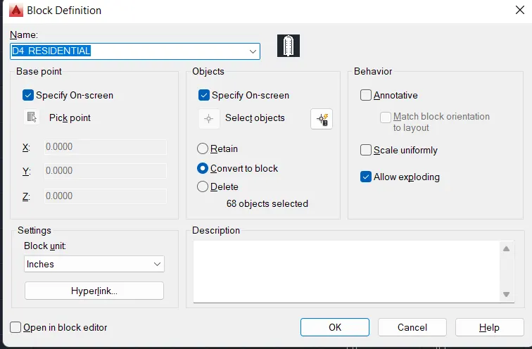
type I-insert the block in the drawing sheet as shown in the fig below.
select the custom_1 title block to insert into the drawing sheet.
select the insertion point to where we needed this block.
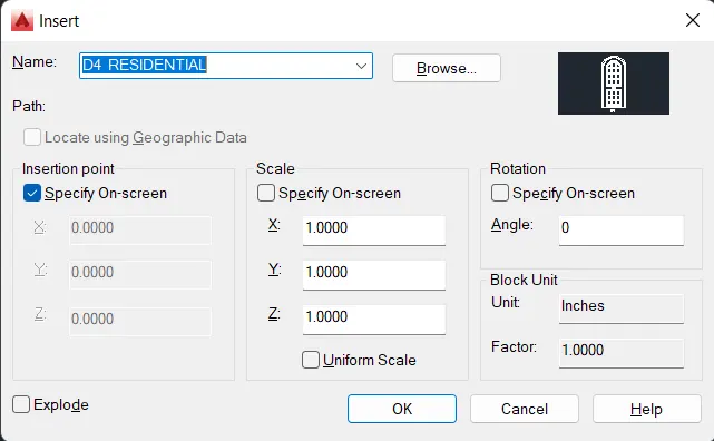
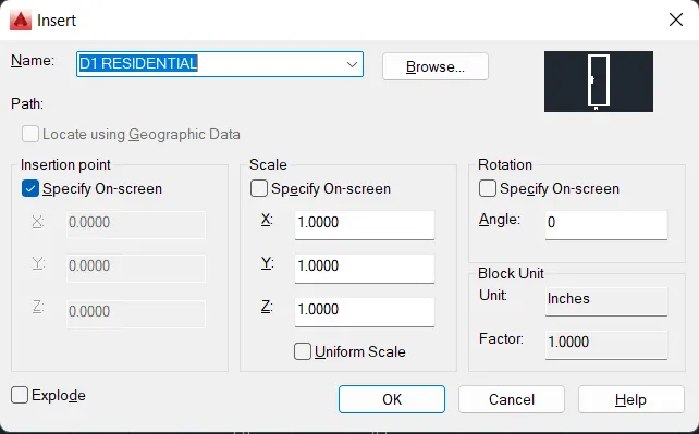
Result: The follwing symbol legend is completed and converted to block.
5)AIM
to draw the symbol legend and save it as block.
INTRODUCTION
This symbol legend is created using autocad and the procedure is explained in detail in each steps and the commands are used in this drawing are.
COMMANDS USED IN THIS DRAWING
- L- LINE
- F8- ORTHO MODE
- GRIDMODE
- F10 - POLAR TRACKING
- ST - STYLE TEXT
- DT-SINGLE TEXT
- T- MULTITEXT
- C- CIRCLE
- CO-COPY
- M-MOVE
- T- TEXT
- TR- TRIM
- O-OFFSET
- F- FILLET
- D-DIMENSION STYLE
- REC-RECTANGLE
- DIMLINEAR
- DIMCONT
- DIMBASE
- LEADER
- QLEADER
- SC-SCALE
- LA-layers
- ADC-design center
- B-Block
- I-insert
- Xl-xline
- H-hatch
PROCEDURE
- open autocad file in windows desktop.
- a dialog box will open it shows startup from scratch.
- click the radio button imperial to start the project.
- in command box type gridmode to show the gridmode by typing 1 in the command box
- type F8 to get ortho on.
- type limmax to set the maximum layout.
- type llmits to set the layout.
- TYPE UN FOR UNITS and set to decimal.
STEP 1
Type L-Line
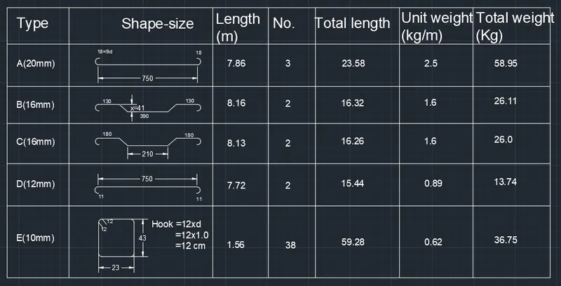
type l for line and draw the symbol legend as shown in fig question 5
draw the reabar shapes as shown in legend as set as block.
each drawing we can easily set the block into the drawing.
type o - offset the line as shown and seprate table is done using this.
type t-mulitiline text to text the switches.
type co- copy the text wherever needed.
after sepratiing each one as block complete this rebar legend and set as block.
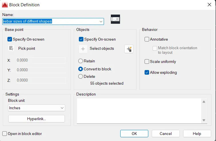
type B-block a dialog box open as shown in the fig below.
after drawn type B- block the title block as one object
select the insertion point of the object.
selct the object on the screen to set as a block
select the convert to block and the drawing will be converted to block.
press ok to convert into a block.
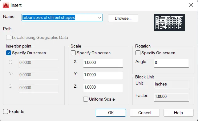
type I-insert the block in the drawing sheet as shown in the fig below.
select the custom_1 title block to insert into the drawing sheet.
select the insertion point to where we needed this block.
Result: The follwing Rebar Shapes is completed and converted to block.