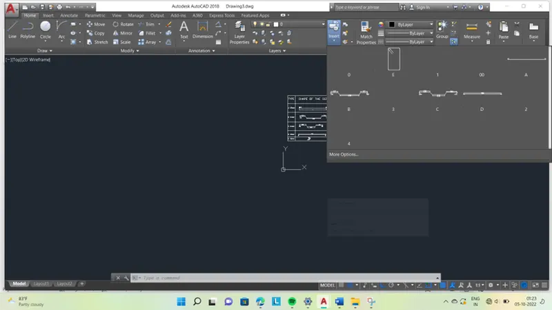
Creating Bar Bending schedule, Different Door types, and Creation of standard drawing templates using AutoCad
Aim:
To create the title block named custom1_titleblock(1.a) and custom2_titleblock (1.b)using block attributes command in AutoCAD .
Introduction :
Various command used while Sketching :
- Line command
- Unit command
- Lim max command
- XL command
- Zoom command
- Arc command
- Trim command
- Text command
- Extent command
- Fillet command
- Rectangle command
- Circle command
- Copy command
- LT command
- Dimension command
- Layer command
- Offset command
- Limits command
- Block command
- Inset command
- Move command
PRODUCTRE :
STEP 1 :
- GO to START MENU ,select AutoCAD 2018.
- Enter “UNITS” command in the command tab.
- Open “ Drawing units “ dialogue box , Type as “Decimal ” and precision as 00
- Then click units scale to “ millimetres ”
- Click “OK”.
- Enter “ LIM MAX” command in the command tab.
- Enter new value for Lim max as 200’.
- Enter “zoom” command in the command box.
- Enter “All” command in the command box.
- Enter “LIMITS” command in the command box.
- Specify lower left corner as
- Enter “zoom “ command in the command box.
- Enter “ALL” command in the command box.
Step 2:
Custom1_titleblock :
- Enter “XL “ (OR) “ X line” command in the command box.
- Specific a point as “Vertical” command in the command box.
- Move the line to somewhere , where you want
- Than click “ESC” command in the command box.
- Enter “XL “ (OR) “ X line” command in the command box.
- Specific a point as “Horizontal” command in the command box.
- Move the horizontal line to close to the vertical line.
- Than click “ESC” command in the command box.
- Create table as per the drawing .
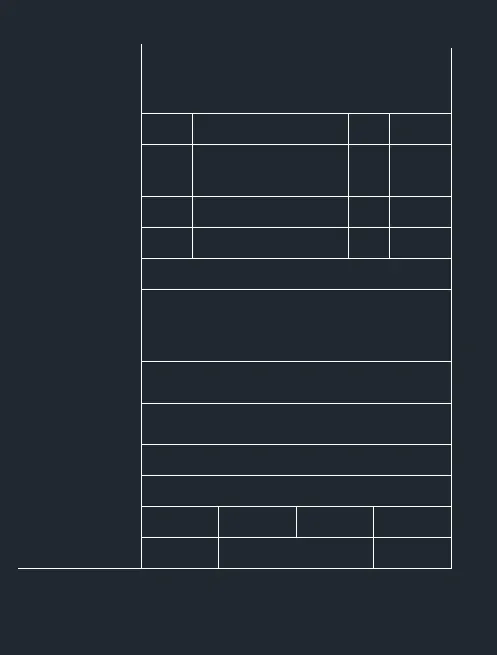
- Enter “TEXT” command in the command box.
- Specify the point of text , inside of the table
- Give text height as “70mm” some place give text hight as “40mm”
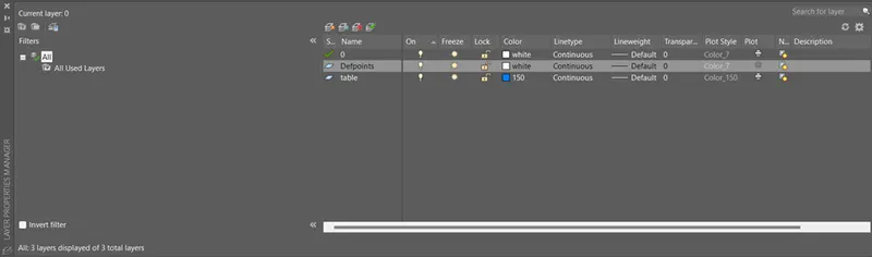
- Go to the “HOME” Then Double click “PROPRTY LAYOUR”
- U will get dialoge box
- Click “NEW LAYOUR “ and give a name as “TABLE”
- And select the “BLUE” colour
- Apply the colour in the table and texts.
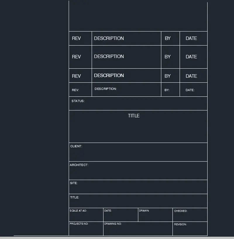
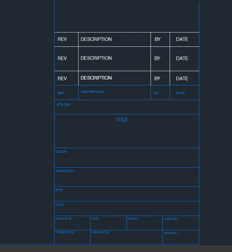
- Enter “BLOCK” command in the command box.
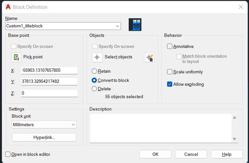
- U will “BLOCK DEFINITION “ dialoge box.
- Give a name as “Custom1_titleblock”
- Then click “SELECT OBJECTS”
- Then click “CONVERT TO BLOCK”
- Select “PICK PIONT “
- Give a description if you want to note .
- Click “OK”
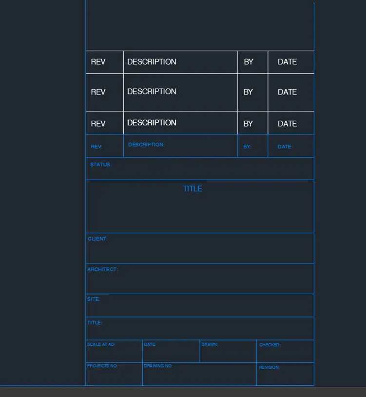
- Finally convert the table as block and show the result .
RESULT : CUSTOME1_TITLEBLOCK
CREATING CUSTOM2_TITLEBLOCK :
- Enter “XL “ (OR) “ X line” command in the command box.
- Specific a point as “Vertical” command in the command box.
- Move the line to somewhere , where you want
- Than click “ESC” command in the command box.
- Enter “XL “ (OR) “ X line” command in the command box.
- Specific a point as “Horizontal” command in the command box.
- Move the horizontal line to close to the vertical line.
- Than click “ESC” command in the command box.
- Create table as per the drawing .
- Create a table as per the question
- Enter “TEXT” command in the command box.
- Specify the point of text , inside of the table
- Give text height as “70mm” some place give text hight as “40mm”
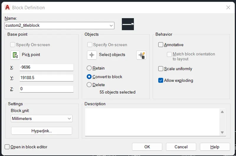
- Enter “BLOCK” command in the command box.
- U will “BLOCK DEFINITION “ dialoge box.
- Give a name as “Custom1_titleblock”
- Then click “SELECT OBJECTS”
- Then click “CONVERT TO BLOCK”
- Select “PICK PIONT “
- Give a description if you want to note .
- Click “OK”
- Finally convert the table as block and show the result .
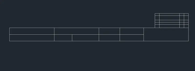
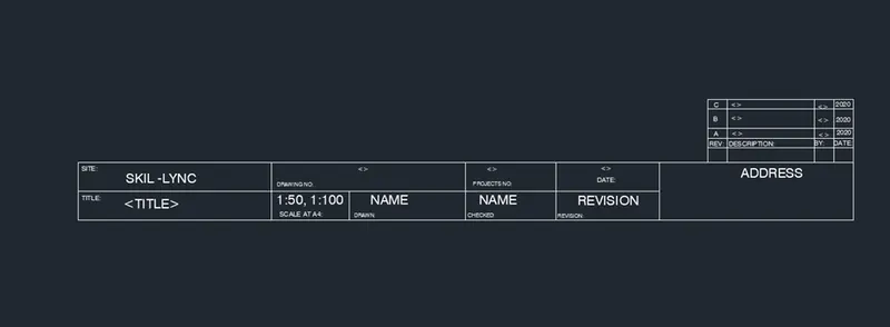
RESULT : CUSTOM2_TITLEBLOCK
Aim:
To create the door types for warehouse and convert the same into blocks .
Introduction :
Various command used while Sketching :
- Line command
- Unit command
- Lim max command
- XL command
- Zoom command
- Arc command
- Trim command
- Text command
- Extent command
- Fillet command
- Rectangle command
- Circle command
- Copy command
- LT command
- Dimension command
- Layer command
- Offset command
- Limits command
- Block command
- Inset command
- Move command
PRODUCTRE :
STEP 1 :
- GO to START MENU ,select AutoCAD 2018.
- Enter “UNITS” command in the command tab.
- Open “ Drawing units “ dialogue box , Type as “Decimal ” and precision as 00
- Then click units scale to “ millimetres ”
- Click “OK”.
- Enter “ LIM MAX” command in the command tab.
- Enter new value for Lim max as
- Enter “zoom” command in the command box.
- Enter “All” command in the command box.
- Enter “LIMITS” command in the command box.
- Specify lower left corner as
- Enter “zoom “ command in the command box.
- Enter “ALL” command in the command box.
Step 2:
Creating DOOR 1
- Enter “XL “ (OR) “ X line” command in the command box.
- Specific a point as “Vertical” command in the command box.
- Move the line to somewhere , where you want
- Than click “ESC” command in the command box.
- Enter “XL “ (OR) “ X line” command in the command box.
- Specific a point as “Horizontal” command in the command box.
- Move the horizontal line to close to the vertical line.
- Than click “ESC” command in the command box.
- Enter “OFFSET” command in the command box .
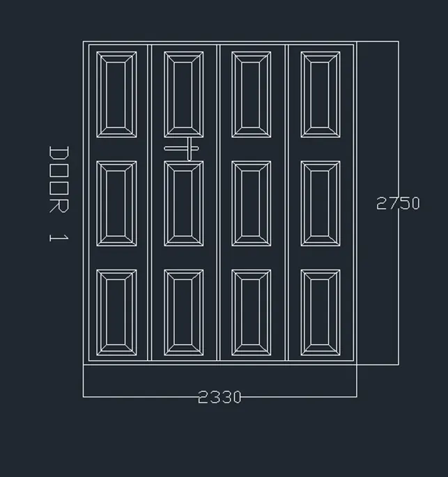
- Give a value of “2330mm” in X axis
- Enter “OFFSET” command in the command box .
- Give a value of “2750mm” in Y axis
- Enter “TRIM” command in the command box .
- Trimmed unwanted lines in the drawing .
- Enter “REC” command in the command box.
- Create a rectangle box inside of the door.
- Enter “DIMLINER” command in the command box.
- Give a name as “DOOR 1”
- Enter “BLOCK” command in the command box.
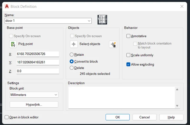
- U will “BLOCK DEFINITION “ dialoge box.
- Give a name as “DOOR 1”
- Then click “SELECT OBJECTS”
- Then click “CONVERT TO BLOCK”
- Select “PICK PIONT “
- Give a description if you want to note .
- Click “OK”
- Finally convert the table as block and show the result .
RESULT:
DOOR 1
CREATING DOOR 2
Step 3:
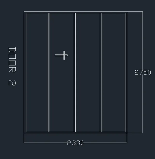
Creating DOOR 2
- Enter “XL “ (OR) “ X line” command in the command box.
- Specific a point as “Vertical” command in the command box.
- Move the line to somewhere , where you want
- Than click “ESC” command in the command box.
- Enter “XL “ (OR) “ X line” command in the command box.
- Specific a point as “Horizontal” command in the command box.
- Move the horizontal line to close to the vertical line.
- Than click “ESC” command in the command box.
- Enter “OFFSET” command in the command box .
- Give a value of “2330mm” in X axis
- Enter “OFFSET” command in the command box .
- Give a value of “2750mm” in Y axis
- Enter “TRIM” command in the command box .
- Trimmed unwanted lines in the drawing .
- Enter “OFFSET” command in the command box.
- Create a rectangle box inside of the door.
- Enter “DIMLINER” command in the command box.
- Give a name as “DOOR 2”
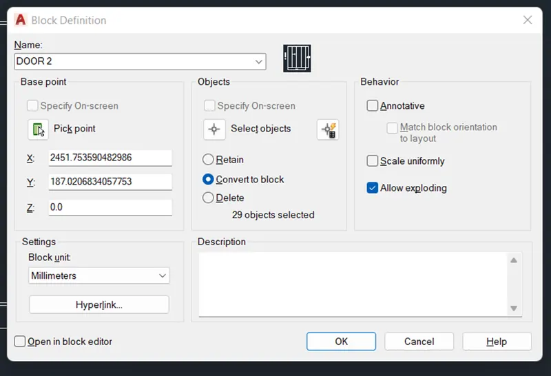
- Enter “BLOCK” command in the command box.
- U will “BLOCK DEFINITION “ dialoge box.
- Give a name as “DOOR 2”
- Then click “SELECT OBJECTS”
- Then click “CONVERT TO BLOCK”
- Select “PICK PIONT “
- Give a description if you want to note .
- Click “OK”
- Finally convert the table as block and show the result .
RESULT:
DOOR 2
AIM :
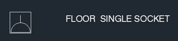
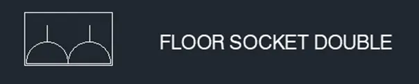
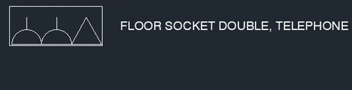
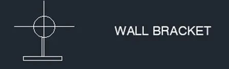
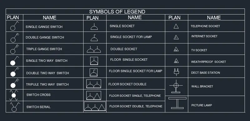
TO Create a symbol legend with each symbol as block with the name .
Introduction :
Various command used while Sketching :
- Line command
- Unit command
- Lim max command
- XL command
- Zoom command
- Arc command
- Trim command
- Text command
- Extent command
- Fillet command
- Rectangle command
- Circle command
- Copy command
- LT command
- Dimension command
- Layer command
- Offset command
- Limits command
- Block command
- Inset command
- Move command
PRODUCTRE :
STEP 1 :
- GO to START MENU ,select AutoCAD 2018.
- Enter “UNITS” command in the command tab.
- Open “ Drawing units “ dialogue box , Type as “Decimal ” and precision as 00
- Then click units scale to “ millimetres ”
- Click “OK”.
- Enter “ LIM MAX” command in the command tab.
- Enter new value for Lim max as 10000’.
- Enter “zoom” command in the command box.
- Enter “All” command in the command box.
- Enter “LIMITS” command in the command box.
- Specify lower left corner as
- Enter “zoom “ command in the command box.
- Enter “ALL” command in the command box.
STEP 2:
- First will create symbol using CIRCLE , REC, LINE ,ARC command in the command
- Create symbol as per the question .
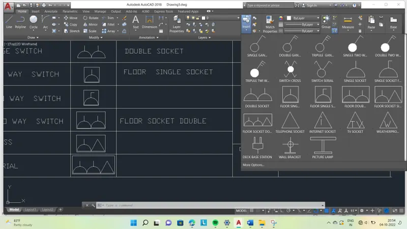
- Create a blocks each symbols
- Enter “BLOCK” command in the command box.
- U will “BLOCK DEFINITION “ dialoge box.
- Give a name as “DOOR 2”
- Then click “SELECT OBJECTS”
- Then click “CONVERT TO BLOCK”
- Select “PICK PIONT “
- Give a description if you want to note .
- Click “OK”
- Finally convert the table as block and show the result .
RESULT:



















Aim:
To create the door types for residential building as block
Introduction :
Various command used while Sketching :
- Line command
- Unit command
- Lim max command
- XL command
- Zoom command
- Arc command
- Trim command
- Text command
- Extent command
- Fillet command
- Rectangle command
- Circle command
- Copy command
- LT command
- Dimension command
- Layer command
- Offset command
- Limits command
- Block command
- Inset command
- Move command
PRODUCTRE :
STEP 1 :
- GO to START MENU ,select AutoCAD 2018.
- Enter “UNITS” command in the command tab.
- Open “ Drawing units “ dialogue box , Type as “ENGINEERING ” and precision as 00
- Then click units scale to “ INCHES ”
- Click “OK”.
- Enter “ LIM MAX” command in the command tab.
- Enter new value for Lim max as 200’.
- Enter “zoom” command in the command box.
- Enter “All” command in the command box.
- Enter “LIMITS” command in the command box.
- Specify lower left corner as
- Enter “zoom “ command in the command box.
- Enter “ALL” command in the command box.
Step 2:
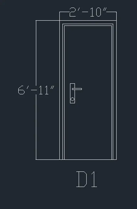
Creating DOOR 1
- Enter “XL “ (OR) “ X line” command in the command box.
- Specific a point as “Vertical” command in the command box.
- Move the line to somewhere , where you want
- Than click “ESC” command in the command box.
- Enter “XL “ (OR) “ X line” command in the command box.
- Specific a point as “Horizontal” command in the command box.
- Move the horizontal line to close to the vertical line.
- Than click “ESC” command in the command box.
- Enter “OFFSET” command in the command box .
- Give a value of 2’-10” in X axis
- Enter “OFFSET” command in the command box .
- Give a value of 6’-11” in Y axis
- Enter “TRIM” command in the command box .
- Trimmed unwanted lines in the drawing .
- Enter “OFFSET” command in the command box.
- Create a rectangle box inside of the door.
- Enter “DIMLINER” command in the command box.
- Give a name as “DOOR 1”
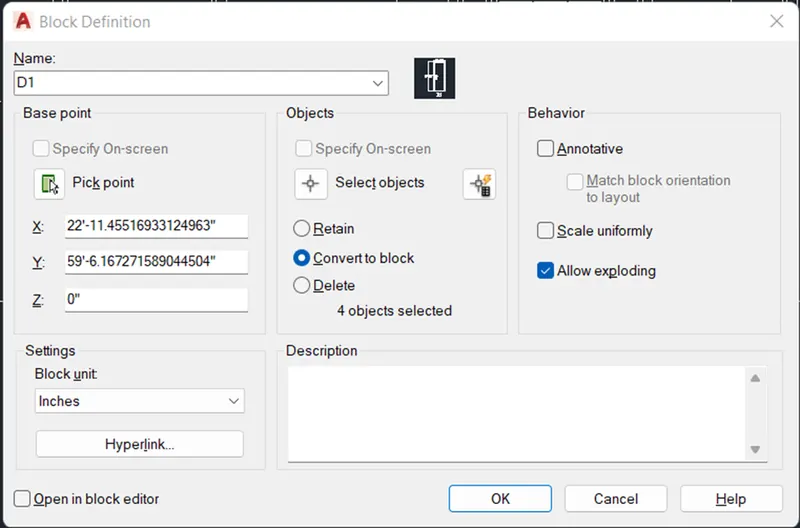
- Enter “BLOCK” command in the command box.
- U will “BLOCK DEFINITION “ dialoge box.
- Give a name as “DOOR 1”
- Then click “SELECT OBJECTS”
- Then click “CONVERT TO BLOCK”
- Select “PICK PIONT “
- Give a description if you want to note .
- Click “OK”
- Finally convert the table as block and show the result .
RESULT:
DOOR 1
Step 2:
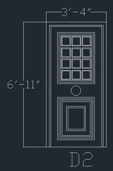
Creating DOOR 2
- Enter “XL “ (OR) “ X line” command in the command box.
- Specific a point as “Vertical” command in the command box.
- Move the line to somewhere , where you want
- Than click “ESC” command in the command box.
- Enter “XL “ (OR) “ X line” command in the command box.
- Specific a point as “Horizontal” command in the command box.
- Move the horizontal line to close to the vertical line.
- Than click “ESC” command in the command box.
- Enter “OFFSET” command in the command box .
- Give a value of 3’-4” in X axis
- Enter “OFFSET” command in the command box .
- Give a value of 6’-11” in Y axis
- Enter “TRIM” command in the command box .
- Trimmed unwanted lines in the drawing .
- Enter “REC” command in the command box.
- Create a rectangle box inside of the door as per the drawing .
- Enter “DIMLINER” command in the command box.
- Give a name as “DOOR 1”
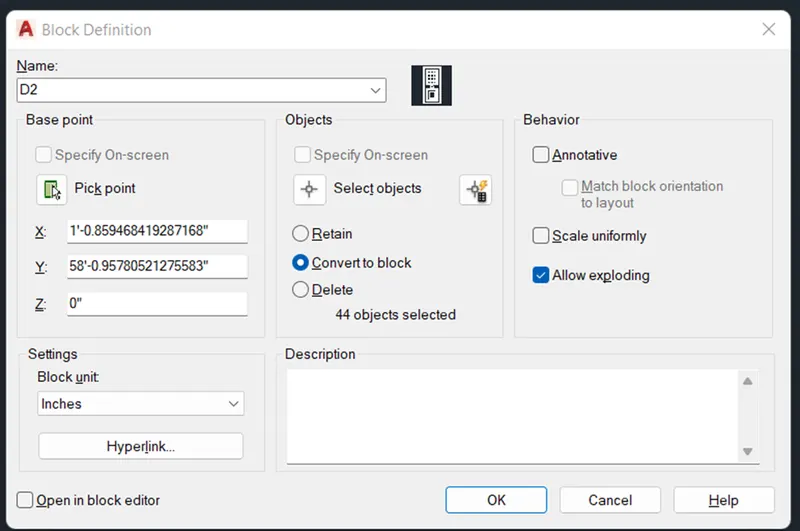
- Enter “BLOCK” command in the command box.
- U will “BLOCK DEFINITION “ dialoge box.
- Give a name as “DOOR 2”
- Then click “SELECT OBJECTS”
- Then click “CONVERT TO BLOCK”
- Select “PICK PIONT “
- Give a description if you want to note .
- Click “OK”
- Finally convert the table as block and show the result .
RESULT :
DOOR 2
Step 3:
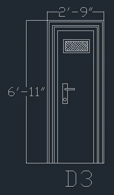
Creating DOOR 3
- Enter “XL “ (OR) “ X line” command in the command box.
- Specific a point as “Vertical” command in the command box.
- Move the line to somewhere , where you want
- Than click “ESC” command in the command box.
- Enter “XL “ (OR) “ X line” command in the command box.
- Specific a point as “Horizontal” command in the command box.
- Move the horizontal line to close to the vertical line.
- Than click “ESC” command in the command box.
- Enter “OFFSET” command in the command box .
- Give a value of 2’-9” in X axis
- Enter “OFFSET” command in the command box .
- Give a value of 6’-11” in Y axis
- Enter “TRIM” command in the command box .
- Trimmed unwanted lines in the drawing .
- Enter “REC” command in the command box.
- Create a rectangle box inside of the door as per the drawing .
- Enter “DIMLINER” command in the command box.
- Give a name as “DOOR 3”
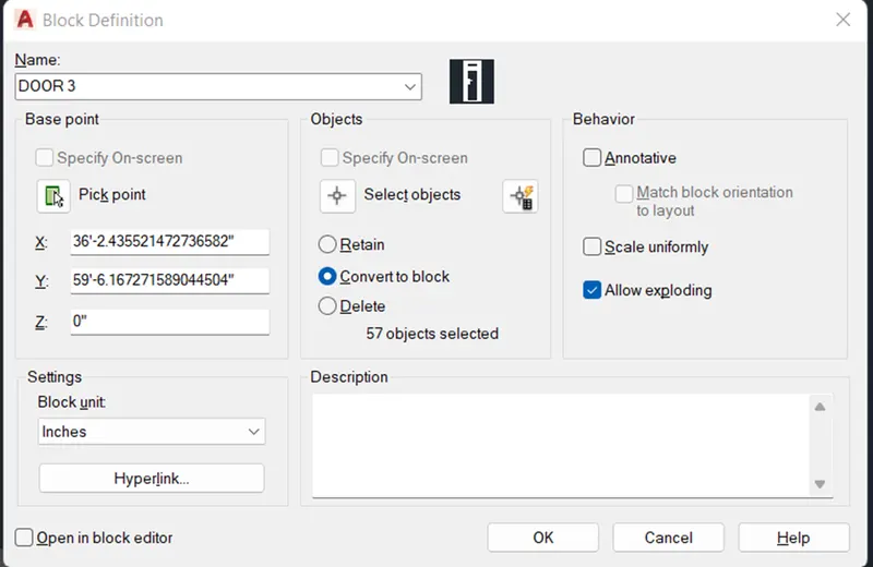
- Enter “BLOCK” command in the command box.
- U will “BLOCK DEFINITION “ dialoge box.
- Give a name as “DOOR 3”
- Then click “SELECT OBJECTS”
- Then click “CONVERT TO BLOCK”
- Select “PICK PIONT “
- Give a description if you want to note .
- Click “OK”
- Finally convert the table as block and show the result .
RESULT :
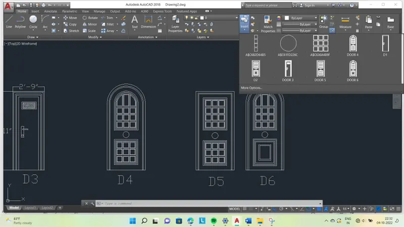
DOOR 3
Step 4:
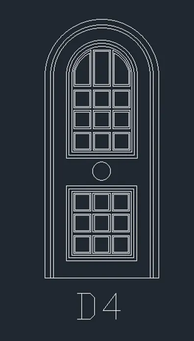
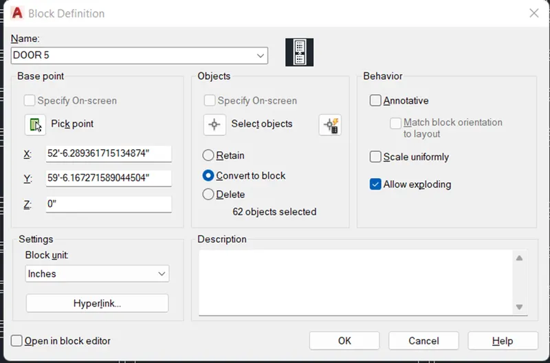
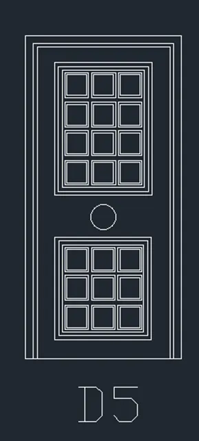
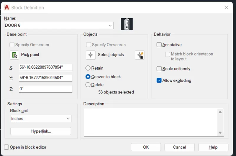
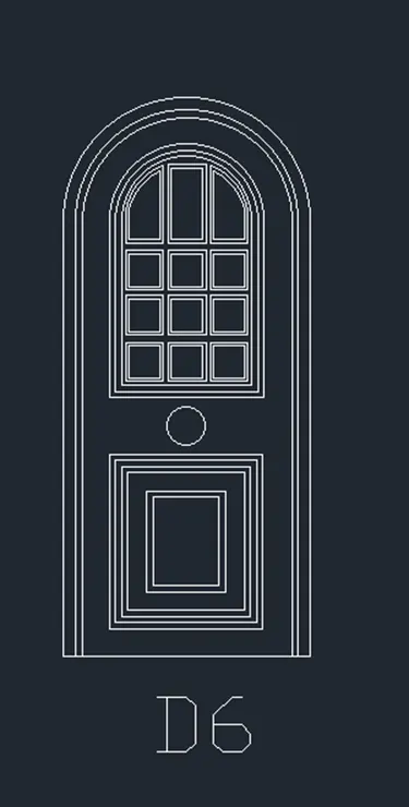
Creating DOOR 4 , DOOR 5 , DOOR6
- Enter “XL “ (OR) “ X line” command in the command box.
- Specific a point as “Vertical” command in the command box.
- Move the line to somewhere , where you want
- Than click “ESC” command in the command box.
- Enter “XL “ (OR) “ X line” command in the command box.
- Specific a point as “Horizontal” command in the command box.
- Move the horizontal line to close to the vertical line.
- Than click “ESC” command in the command box.
- Create a rectangle box inside of the door as per the drawing .
- Will creating three doors at the same time as per the drawing
- Enter “DIMLINER” command in the command box.
- Give a name as “DOOR 4 , DOOR 5, DOOR 6”.
- Create a block each doors as per the drawing
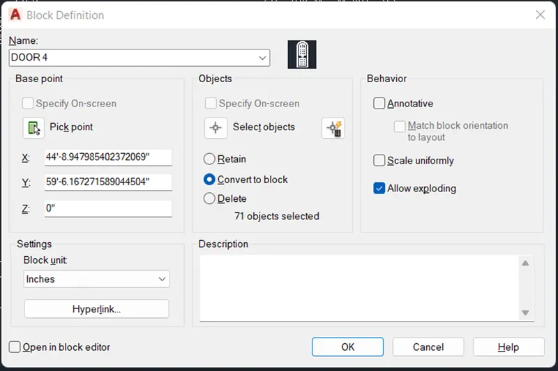
- Enter “BLOCK” command in the command box.
- U will “BLOCK DEFINITION “ dialoge box.
- Give a name as “DOOR 4 , DOOR 5, DOOR6”.
- Then click “SELECT OBJECTS”
- Then click “CONVERT TO BLOCK”
- Select “PICK PIONT “
- Give a description if you want to note .
- Click “OK”
- Finally convert the table as block and show the result .
RESULT :
DOOR 4 , DOOR 5, DOOR 6:
DOOR 5:
DOOR 6:
AIM:
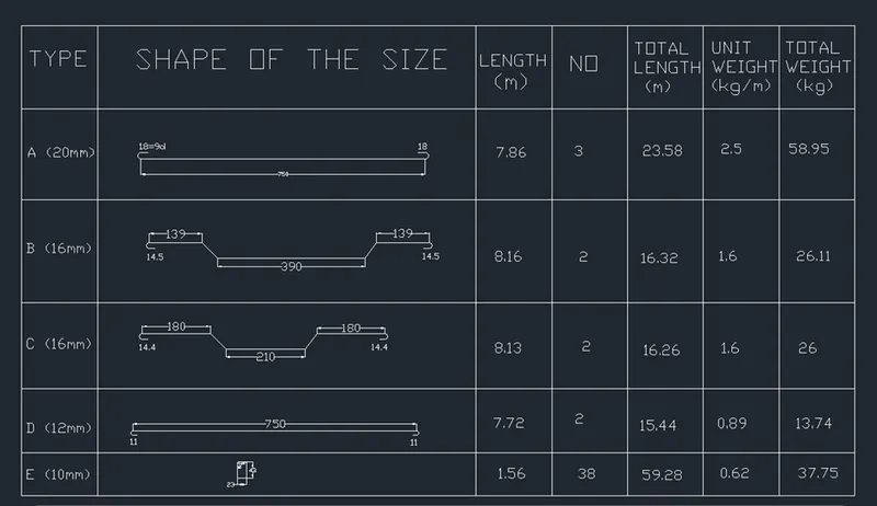
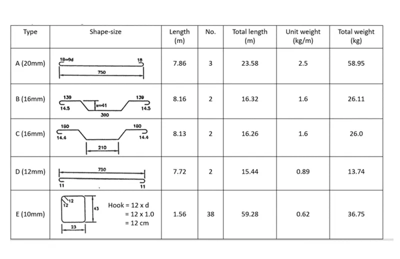
To create each shape as block as shown in the figure and insert the blocks into the table as shown below
Introduction :
Various command used while Sketching :
- Line command
- Unit command
- Lim max command
- XL command
- Zoom command
- Arc command
- Trim command
- Text command
- Extent command
- Fillet command
- Rectangle command
- Circle command
- Copy command
- LT command
- Dimension command
- Layer command
- Offset command
- Limits command
- Block command
- Inset command
- Move command
PRODUCTRE :
STEP 1 :
- GO to START MENU ,select AutoCAD 2018.
- Enter “UNITS” command in the command tab.
- Open “ Drawing units “ dialogue box , Type as “DECIMAL” and precision as 00
- Then click units scale to “ MILLIMETER ”
- Click “OK”.
- Enter “ LIM MAX” command in the command tab.
- Enter new value for Lim max as
- Enter “zoom” command in the command box.
- Enter “All” command in the command box.
- Enter “LIMITS” command in the command box.
- Specify lower left corner as
- Enter “zoom “ command in the command box.
- Enter “ALL” command in the command box.
Step 2:
Creating BLOCKS :
- Enter “LINE” command in the command box .
- Give a value “750mm” and create the line as for the drawing .
- Enter “DIMLINER” command in the command box.
- Give a name as “A”.
- Create a block each doors as per the drawing
- Enter “BLOCK” command in the command box.
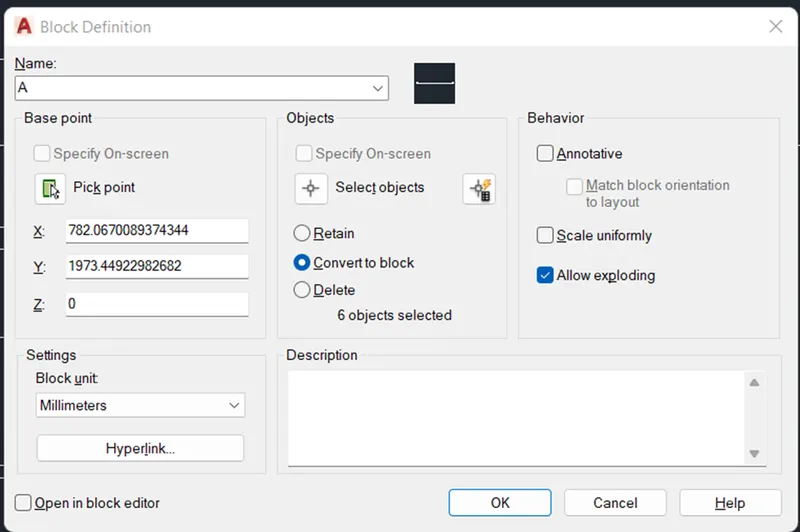
- U will “BLOCK DEFINITION “ dialoge box.
- Give a name as “A”.
- Then click “SELECT OBJECTS”
- Then click “CONVERT TO BLOCK”
- Select “PICK PIONT “
- Give a description if you want to note .
- Click “OK”
- Finally convert the line as block and show the result .
RESULT :


Step 2:
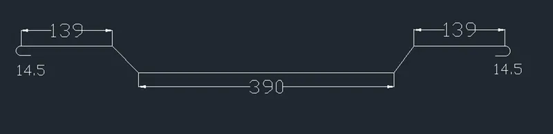
Creating BLOCKS “B” :
- Enter “LINE” command in the command box .
- Give a value “390mm” and “139mm” create the line as for the drawing .
- Enter “DIMLINER” command in the command box.
- Give a name as “B”.
- Create a block each doors as per the drawing
- Enter “BLOCK” command in the command box.
- U will “BLOCK DEFINITION “ dialoge box.
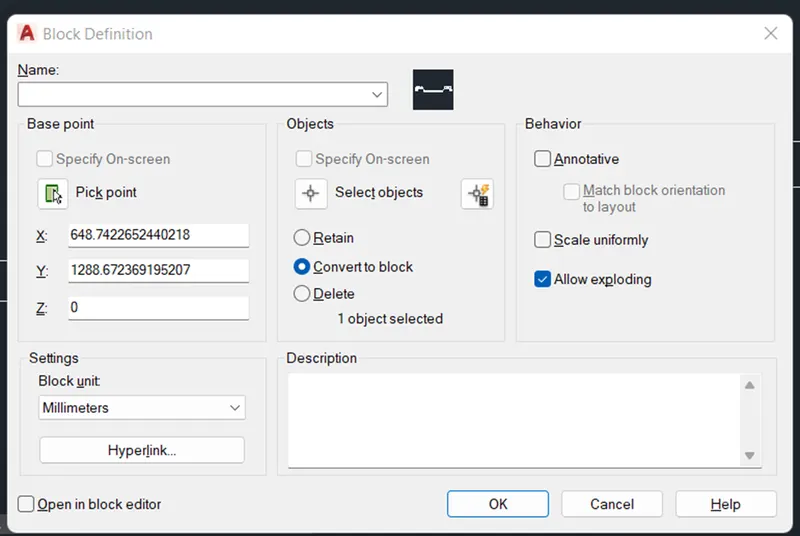
- Give a name as “B”.
- Then click “SELECT OBJECTS”
- Then click “CONVERT TO BLOCK”
- Select “PICK PIONT “
- Give a description if you want to note .
- Click “OK”
- Finally convert the line as block and show the result .
Result :

Step 3:
Creating BLOCKS “C” :
- Enter “LINE” command in the command box .
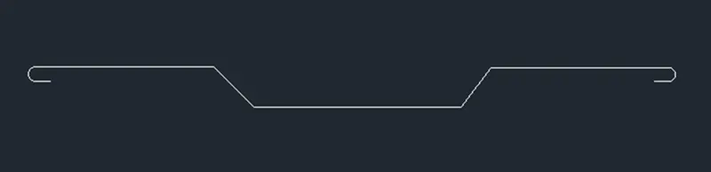
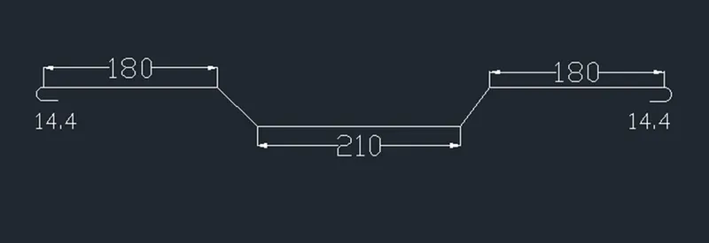
- Give a value “210mm” and “180mm” create the line as for the drawing .
- Enter “DIMLINER” command in the command box.
- Give a name as “C”.
- Create a block each doors as per the drawing
- Enter “BLOCK” command in the command box.
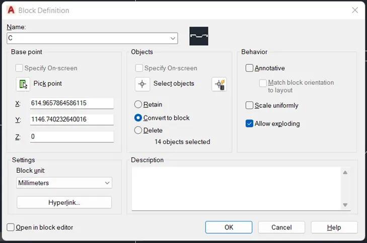
- U will “BLOCK DEFINITION “ dialoge box.
- Give a name as “C”.
- Then click “SELECT OBJECTS”
- Then click “CONVERT TO BLOCK”
- Select “PICK PIONT “
- Give a description if you want to note .
- Click “OK”
- Finally convert the line as block and show the result .
RESULT :
STEP 4:
Creating BLOCKS :
- Enter “LINE” command in the command box .
- Give a value “750mm” and create the line as for the drawing .
- Enter “DIMLINER” command in the command box.
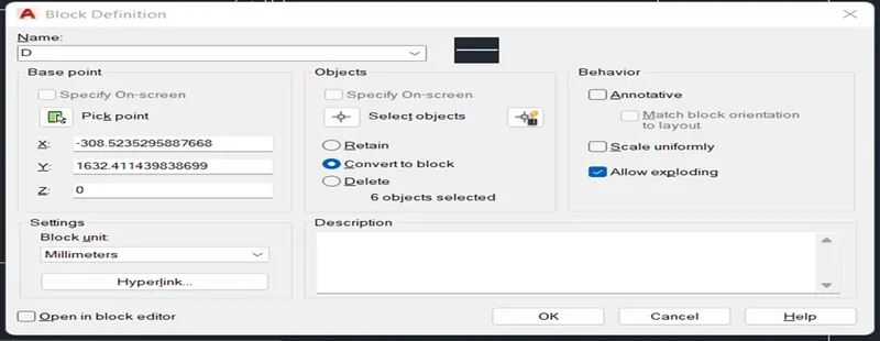
- Give a name as “D”.
- Create a block each doors as per the drawing
- Enter “BLOCK” command in the command box.
- U will “BLOCK DEFINITION “ dialoge box.
- Give a name as “D”.
- Then click “SELECT OBJECTS”
- Then click “CONVERT TO BLOCK”
- Select “PICK PIONT “
- Give a description if you want to note .
- Click “OK”
- Finally convert the line as block and show the result .
RESULT:


Step 5:
Creating BLOCKS “E” :
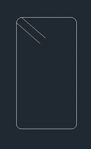
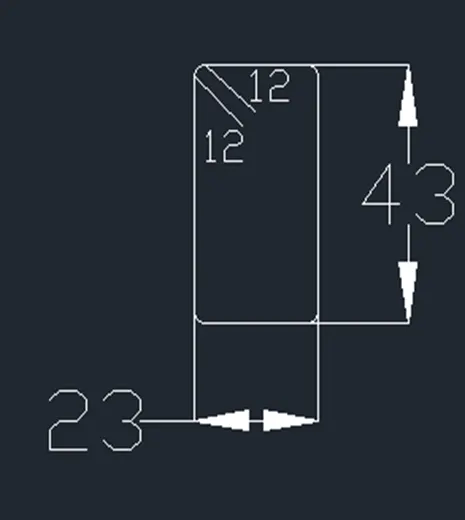
- Enter “LINE” command in the command box .
- Give a value “23mm” Horizontally and “43mm” vertically
- Create a like box .
- Enter “FILLET” command in the command box.
- Apply fillet in each 4 edges
- Enter “DIMLINER” command in the command box.
- Give a name as “E”.
- Enter “TEXT” command in the command box.
- Specify the point of text , inside of the table
- Give text height as “40 mm” some place give text hight as “50mm”
- Create a block each doors as per the drawing
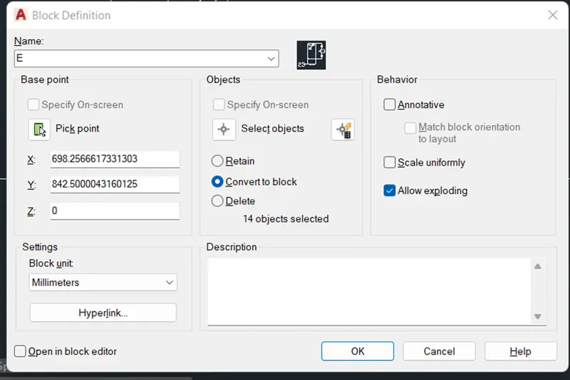
- Enter “BLOCK” command in the command box.
- U will “BLOCK DEFINITION “ dialoge box.
- Give a name as “E”.
- Then click “SELECT OBJECTS”
- Then click “CONVERT TO BLOCK”
- Select “PICK PIONT “
- Give a description if you want to note .
- Click “OK”
- Finally convert the line as block and show the result .
RESULT :