Creating Bar Bending schedule, Different Door types, and Creation of standard drawing templates using AutoCad
AIM: Create the templates as shown in Figures. Take the size of the title block as per industry standards or you can assume it as per the size of the paper. Use text and attributes wherever required. After creating the title block you need to save it as a block with names: Custom1_titleblock and Custom2_titleblock, respectively.
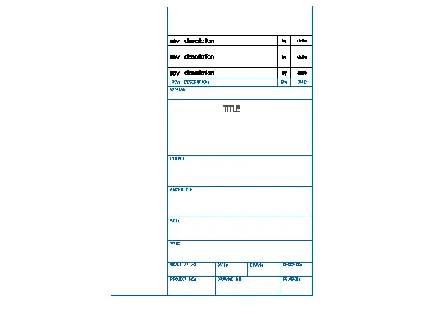
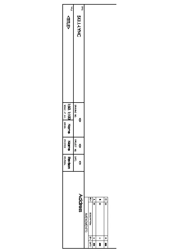
PROCEDURE:
Type UN and press enter
Under Drawing Units, select ENGINEERING
Now the lower limit is set to 0, 0 and upper limit to 50',50'
Type Z enter to zoom and A enter to all
To create a Layer
In the Layer Properties Manager, click New Layer.
A layer name is added to the layer list.
Enter a new layer name as TABLE by typing over the highlighted layer name.
Select a suitable colour for that layer and set this layer as the default layer.
Using the line command a table was drawn as shown in below.
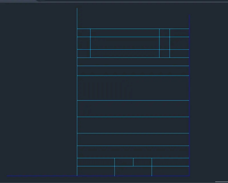
A new layer is now created, named as texts and a suitable colour is selected and this layer is made as the default.
Type ST to open the TEXT STYLE manager.
Now using the MULTI LINE text all the text was entered at the positions as required
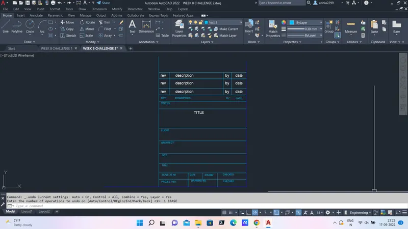
Now create the BLOCK by B command and seclect the object, specify the object point,now NAME the object in the dialogbox, as shown below.
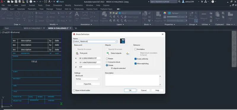
Now again repeat the same for the CUSTOM2_titleblock.
In the Layer Properties Manager, click New Layer.
A layer name is added to the layer list.
Enter a new layer name as TABLE by typing over the highlighted layer name.
Select a suitable colour for that layer and set this layer as the default layer.
Using the line command a table was drawn as shown in below.
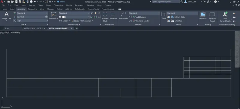
A new layer is now created, named as texts and a suitable colour is selected and this layer is made as the default.
Type ST to open the TEXT STYLE manager.
Now using the MULTI LINE text all the text was entered at the positions as required
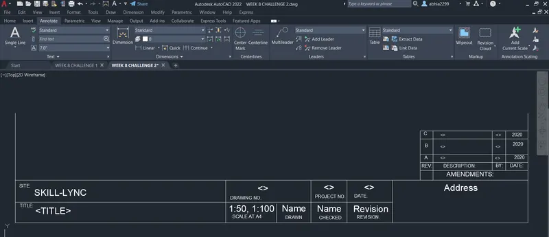
Now create the BLOCK by B command and seclect the object, specify the object point,now NAME the object in the dialogbox, as shown below.
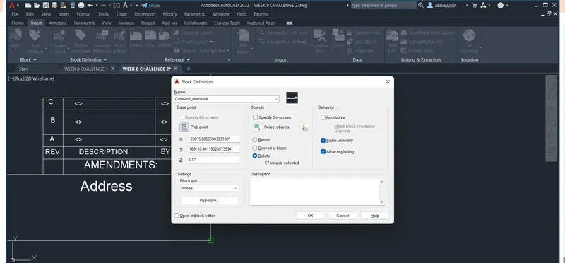
RESULT: Custom1_titleblock and Custom2_titleblock are created.
2Q:
2. Create the doors type for warehouse as shown in the Figure. You need to create each door type as per standard size or given dimensions. Create the blocks of this door type after creating them.
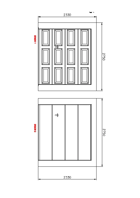
PROCEDURE:
Type UN and press enter
Under Drawing Units, select ENGINEERING
Now the lower limit is set to 0, 0 and upper limit to 50',50'
Type Z enter to zoom and A enter to all.
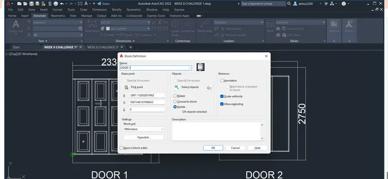
Using the Line command, offset, trim, extend, fillet command and the dimensions given in figure the following portion of door was created.
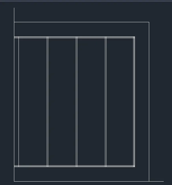
Now using the RECTANGLE command draw a rectangle, give the offset of 20, 40.
Now using the ARRAY command rectengle 4 columns and 3 rows are created, as shown in below.
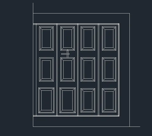
Now give dimensions to the door by DIMLIN command and TEXT by usinng the MTEXT command.
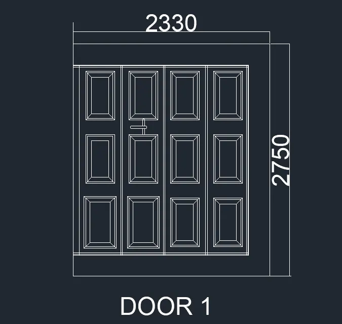
Now create the BLOCK by B command and seclect the object,
specify the object point,
now NAME the object in the dialogbox, as shown below.
DOOR 2:
Draw the rectangle of size 2330 X 2750 mm.
Then offset the lines with 50 mm.
After dividing the line in 4 parts.
Now give dimensions to the door by DIMLIN command and TEXT by usinng the MTEXT command.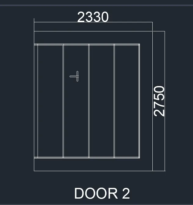
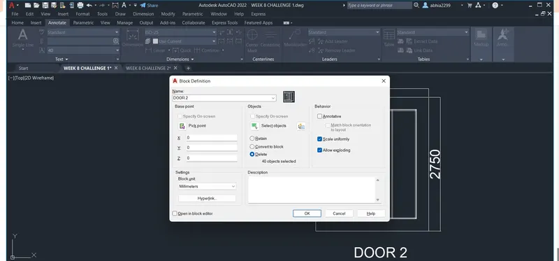
Now create the BLOCK by B command and seclect the object,
specify the object point,
now NAME the object in the dialogbox, as shown below.
RESULT: DOOR1, DOOR2 block are created in te AUTOCAD.
3Q:
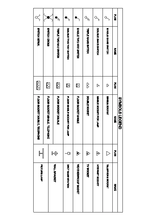
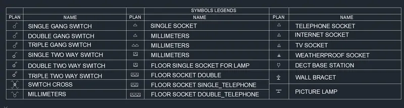
Create each symbol as a block with the name given in the legend. After creating the blocks arrange them in the legend as shown in the Figure.
PROCEDURE:
Now create the symbols for the block and draw the table.
By using the LINE,CIRCLE commands draw a symbol of SINGLE GANG SWITCH.

Now by using the LINE,CIRCLE,TRIM,HATCH, TEXT commands create the all symbols from the table as shown below.
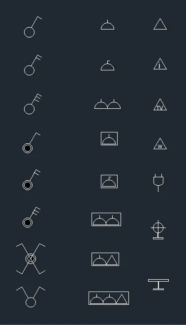
Now create the BLOCK by B command and seclect the object,
specify the object point,
now NAME the object in the dialogbox, as shown below.
Repeat the same process for all the Symbols.
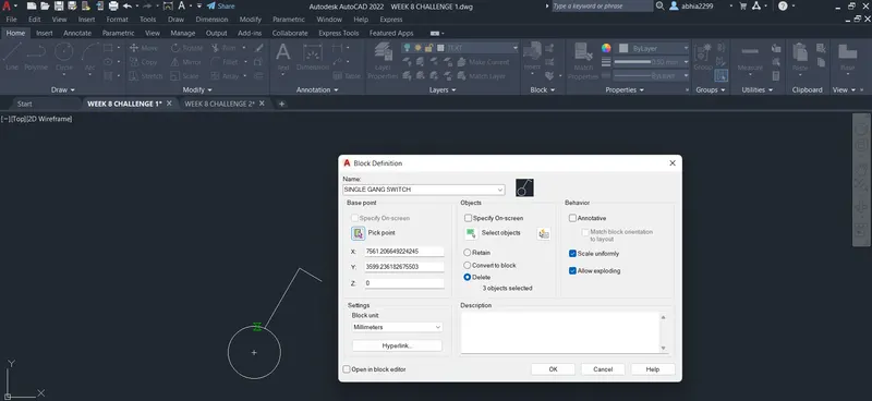
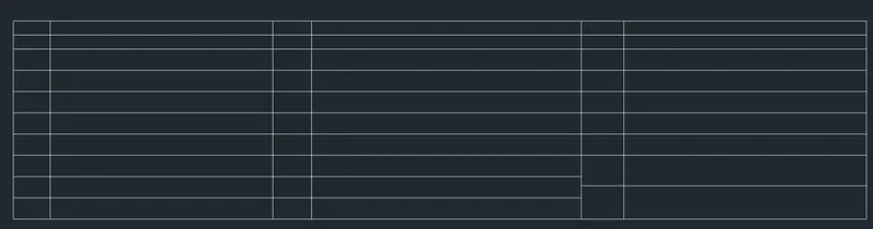
Now draw the table by using the LINE,OFFSET commands.
By using the INSERT command insert the SYMBOLS in the table as shown below.
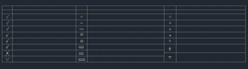
Now in the dialogbox chose INSERT and select the FIELD,
In the field category chose OBJECT,
select the OBJECT and chose the UPPER CASE and insert the TEXT in the TABLE
Now repeat the same procedure for all the symbols.
RESULT:
Created the symbol as a block with the name given in the legend and inserted in the table.
4Q:
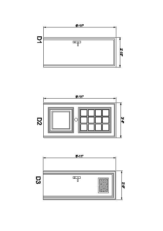
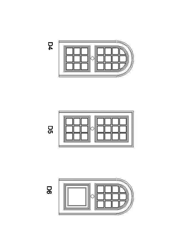
AIM:Create the door type for residential building as a block. Save the name of the blocks as type. Use given dimensions or assume dimensions as per industry standards.
PROCEDURE:
Type UN and press enter
Under Drawing Units, select ENGINEERING
Now the lower limit is set to 0, 0 and upper limit to 50',50'
Type Z enter to zoom and A enter to all.
DOOR 1:
REC command draw a RECTANGLE of 6'1'' height, 2'10" width.
Using OFFSET command offset the line of 1" and and 1.5".
Using MTEXT,DIMLIN commands give the Dimensions and Text to the drawing.
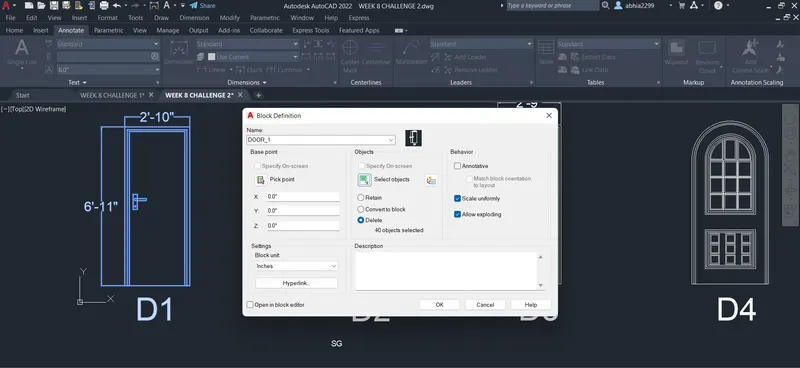
Now create the BLOCK by B command and seclect the object,
specify the object point,
now NAME the object in the dialogbox, as shown below.
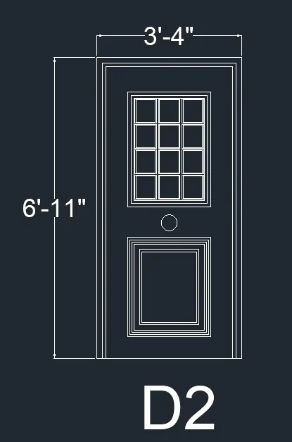
DOOR 2:
REC command draw a RECTANGLE of 6'11'' height, 3'4" width.
Using OFFSET command offset the line of 1" and and 1.5".
draw a rectangle and offfset it 0.6",and using the ARRAY command arraw the rectangle as shown in the plan.
Using MTEXT,DIMLIN commands give the Dimensions and Text to the drawing.
Now create the BLOCK by B command and seclect the object,
specify the object point,
now NAME the object in the dialogbox, as shown below.
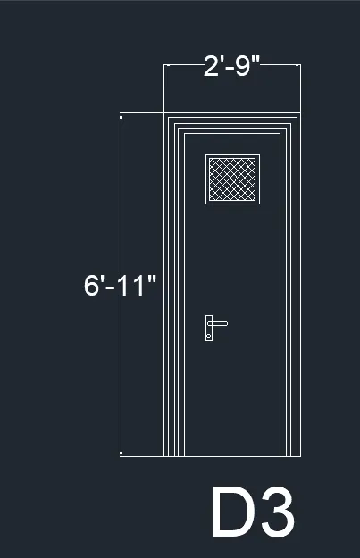
DOOR 3:
REC command draw a RECTANGLE of 6'11'' height, 2'9" width.
Using OFFSET command offset the line of 1" and and 1.5".
Draw a rectanlf and offset it of 0.6" and using HATCH command hatch it .
Using MTEXT,DIMLIN commands give the Dimensions and Text to the drawing.
Now create the BLOCK by B command and seclect the object,
specify the object point,
now NAME the object in the dialogbox, as shown below.
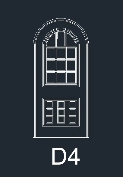
DOOR 4:
REC command draw a RECTANGLE of 6'11'' height, 3'4" width,Using offset command offset it of 1.5"Aand trim it.
Now usinng ARC command draw a arch and JOIN the arch and the lines.
Using OFFSET command offset the line of 0.8" and and 1.5".
draw a rectangle and offfset it 0.6",and using the ARRAY command arraw the rectangle as shown in the plan.
Using MTEXT,DIMLIN commands give the Dimensions and Text to the drawing.
Now create the BLOCK by B command and seclect the object,
specify the object point,
now NAME the object in the dialogbox, as shown below.
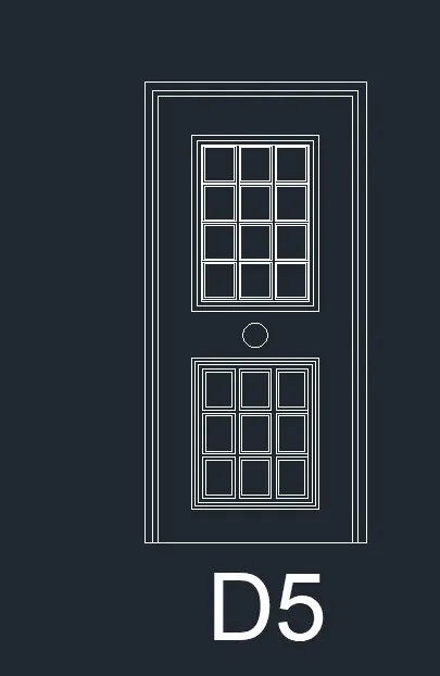
DOOR 5:
REC command draw a RECTANGLE of 6'11'' height, 3'4" width.
Using OFFSET command offset the line of 1" and and 1.5".
draw a rectangle and offfset it 0.6",and using the ARRAY command arraw the rectangle as shown in the plan.
Using MTEXT,DIMLIN commands give the Dimensions and Text to the drawing.
Now create the BLOCK by B command and seclect the object,
specify the object point,
now NAME the object in the dialogbox, as shown below.
DOOR 6:
REC command draw a RECTANGLE of 6'11'' height, 3'4" width,Using offset command offset it of 1.5"Aand trim it.
Now usinng ARC command draw a arch and JOIN the arch and the lines.
Using OFFSET command offset the line of 0.8" and and 1.5".
draw a rectangle and offfset it 0.6",and using the ARRAY command arraw the rectangle as shown in the plan.
Using MTEXT,DIMLIN commands give the Dimensions and Text to the drawing.
Now create the BLOCK by B command and seclect the object,
specify the object point,
now NAME the object in the dialogbox, as shown below.
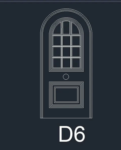
RESULT: Created the door type for residential building as a block
5Q:
AIM:Create each shape as a block as shown in the Figure. Save the block and insert them on the table as shown in the Figure.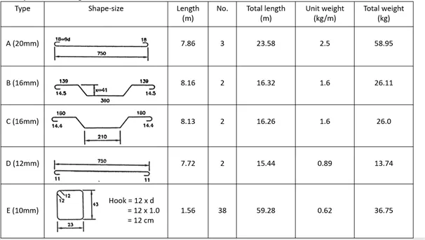
PROCEDURE:
Type UN and press enter
Under Drawing Units, select ENGINEERING
Now the lower limit is set to 0, 0 and upper limit to 50',50'
Type Z enter to zoom and A enter to all
Draw a line of 750 cm.
by using ARCH cmommand draw a arch of 18 dia at the corner end, Using the MIRROR command place it at both the ends.
By DIMLIN command give the DIMENSIONS.
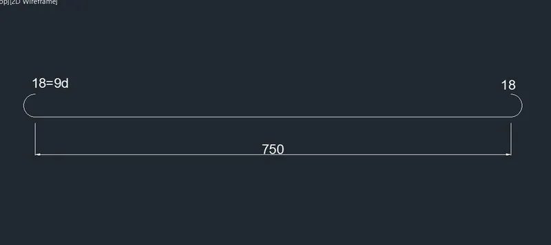
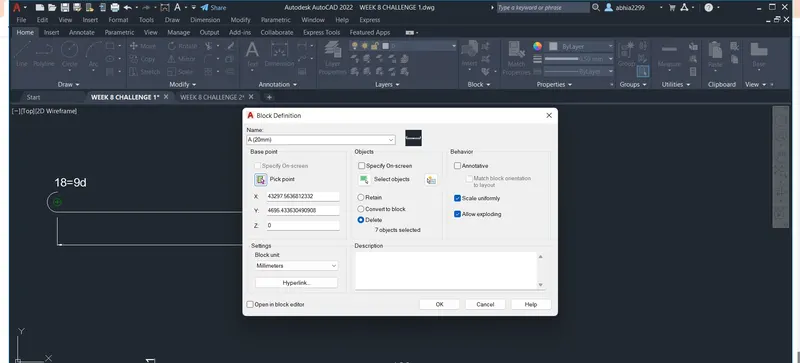
Now create the BLOCK by B command and seclect the object,
specify the object point,
now NAME the object in the dialogbox, as shown below.
B:
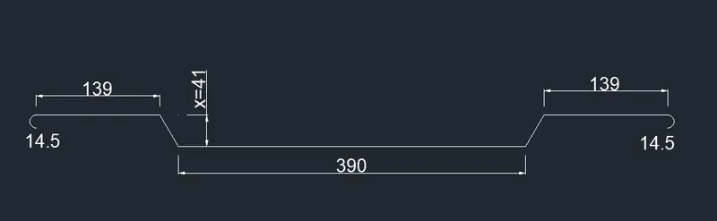
Draw the LINE of 300 cm and using PLOAR TRACKING 45 angle draw A LINE 41 cm and 139 cm horizontal.
by using ARCH cmommand draw a arch of 14.5 dia at the corner end, Using the MIRROR command place it at both the ends.
By DIMLIN command give the DIMENSIONS.
Now create the BLOCK by B command and seclect the object,
specify the object point,
C:
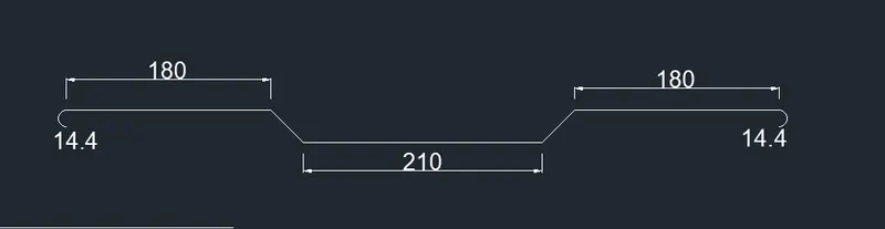
Draw the LINE of 210 cm and using PLOAR TRACKING 45 angle draw A LINE 41 cm and 180 cm horizontal.
by using ARCH cmommand draw a arch of 14.4 dia at the corner end, Using the MIRROR command place it at both the ends.
By DIMLIN command give the DIMENSIONS.
Now create the BLOCK by B command and seclect the object,
specify the object point,
D:
Draw a line of 750 cm.
by using ARCH cmommand draw a arch of 18 dia at the corner end, Using the MIRROR command place it at both the ends.
By DIMLIN command give the DIMENSIONS.
Now create the BLOCK by B command and seclect the object,
specify the object point,

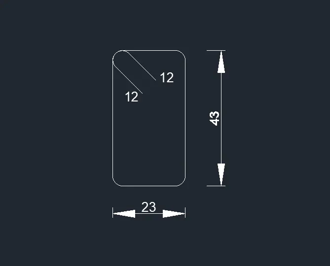
E: Draw a RECTENGLE of height 43, width 23.
draw a hook of 12 by using ARCH.
Using the FILLET Radius Ccurve the rectangle EDGES.
By DIMLIN command give the DIMENSIONS.
Now create the BLOCK by B command and seclect the object,
specify the object point.
Draw a Table by using the LINE, OFFSET commands.
INSERT the symbols in the TABLE.
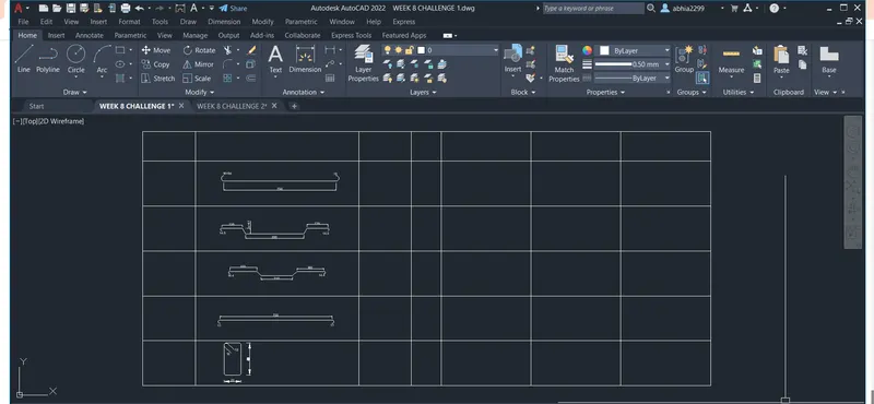
USING the MTEXT command text in the Table as shown in below.
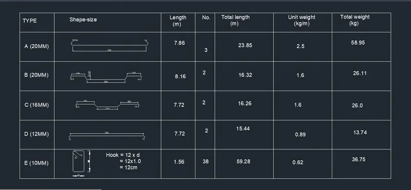
RESULT:Saved the symbols in the block and insert them on the table.