Creating Bar Bending schedule, Different Door types, and Creation of standard drawing templates using AutoCad
1. AIM: To create the templates as shown in Figures.
PROCEDURE:
- Use line command by typing L.
- Draw the schedule as per the illustration.
- Type the texts as indicated in the figure.
- After completing the figure , press B and Enter.
- Select the option pick point.
- Click option select object and name it.
- The second figure is drawn by the same process.
RESULT:
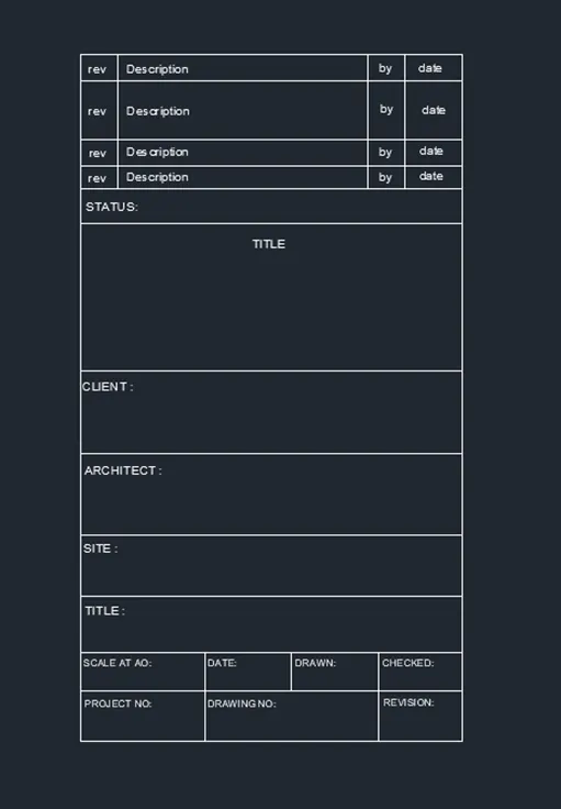
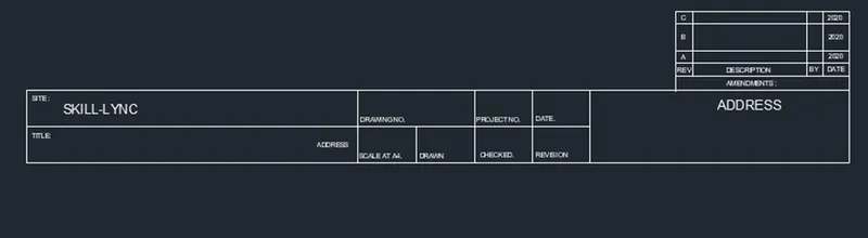
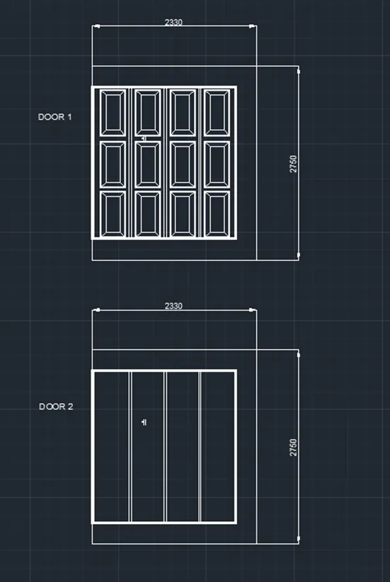
2. AIM: To create the doors type for warehouse as shown in the Figure.
PROCEDURE:
- Open AutoCAD and select Engineering as the measurement unit.
- Draw a rectangle with values 2330,2750.
- Take offsets of 550 units vertically and take the offsets near to it to divide this door into four sections.
- To create the interior panels, simply draw a rectangle, offset it slightly, and then offset it again to the centre.
- Join the lines from all four sides, copy it, and position it wherever it is drawn in the diagram.
- After completing the figure , press B and Enter.
- Select the option pick point.
- Click option select object and name it.
RESULT:
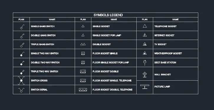
3. AIM: To create each symbol as a block with the name given.
PROCEDURE:
- Open AutoCAD and select Engineering.
- Draw the rows and columns and annotate the texts according to the figure.
- When the figure is finished and B enter is pressed, a dialogue box will open.
- Select the point on the figure by choosing the pick point option.
- Finally choose the item and give it a name by clicking the option pick object.
RESULT:
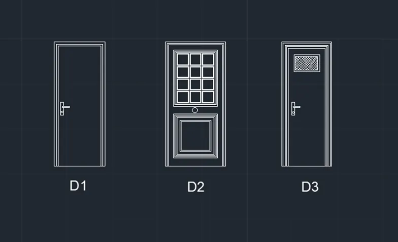
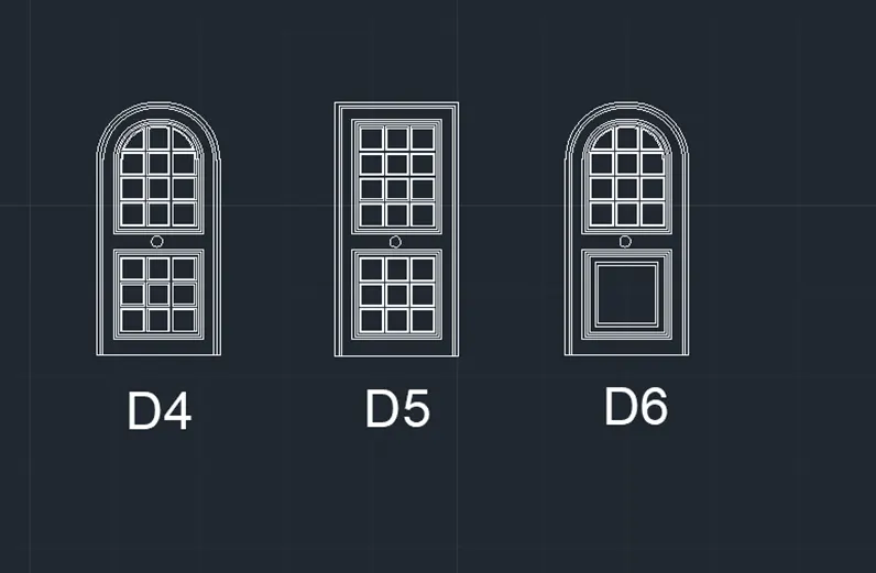
4. AIM: To create the door type for residential building as a block.
PROCEDURE:
- Open AutoCAD and select Engineering.
- Draw a rectangle measuring 6'11" by 2'10".
- Take the offsets of the suppositional dimensions near the top three sides.
- The door latch can be drawn using the rectangle and circle commands.
- For second door, use the rectangle command to draw a 6'11*3'4 rectangle.
- On the top side, draw a second set of rectangles that are closely spaced.
- For the third door, draw a 6'11" by 2'9" rectangle.
- When the figure is finished and B enter is pressed, a dialogue box will open.
- Select the point on the figure by choosing the pick point option.
- Finally choose the item and give it a name by clicking the option pick object.
RESULT:
5. AIM: To create each shape as a block as shown in the Figure.
PROCEDURE:
- Open AutoCAD and, make the units to feet and engineering.
- Use the rec command to draw a rectangle.
- Create the rows and columns as per the illustration.
- Type the texts into the rows and columns you've drawn, as indicated in the figure.
- Using the line command, draw the figures as seen in the shape size column.
- When the figure is finished, press B Enter, and a dialogue box will display.
- Choose the point on the figure by clicking the pick point option.
- After which choose the option to select an object and give it a name.
- When we use the I enter command, the block will be saved.