Creating Bar Bending schedule, Different Door types, and Creation of standard drawing templates using AutoCad
Question1-
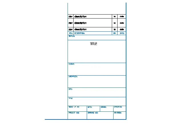
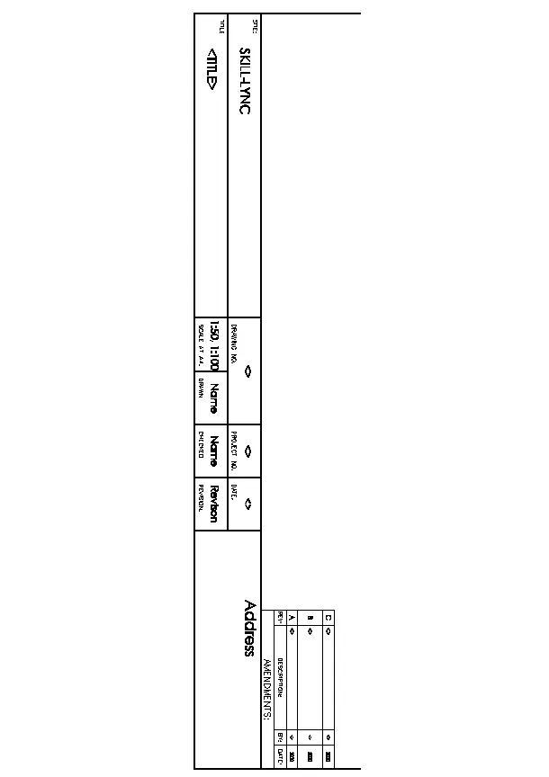
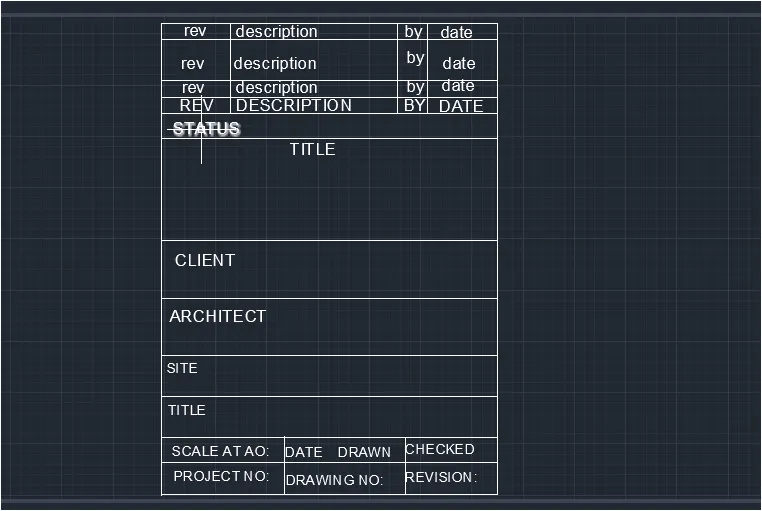
Create the templates as shown in figures.Take the size of the title block as per industry standards or you can assume it as per the size of the paper.Use text and attributes wherever required .After creating the title block you need to save it as a block with names :Custom1-titleblock and Custom2-titleblock,respectively.
ANSWER:
AIM: To create Templets Custom1-titleblock and Custom2-titleblock using attributes and block command from Autocad Software.
INTRODUCTION:
- AUTOCAD- AUTOCAD stands for computer aided designs.
- Autocad is software developed by the company Autodesk.
- It allows you to draw and edit digital 2D and 3d designmore quickly easily than you could byhand.
- This software is used for designing and darfting.
- Autocad is 2D and 3d computer aided drafting software application.
- Autocad software save a huge time ,saving tmie is eaqual to earn more income by more output it is a simple enough software with real user friendly interface.It is easy to grasp and it can provide you the basic exposure it is very benefical in designing 3D.
COMMAND IN AUTOCAD:-
LINE:
Start line command by clickin the line button on the draw panel on the ribbon,or by entering L and then pressing enter.Draw line segments by picking several random points Terminate the command by pressing enterESC or spacebar,Press enter or the spacebar to repeat line command.
DIMENSIONS:
You can select objects or points to dimension,and then click to place the dimesion line.Fim command automtically generates a preview of a suitable dimension type insludes vertical horizontal and aligned linear dimension.
TEXT :
Select tet command frm the annotation menu of the home tab of this software.We have two types of text command in autocad .One is multiline text and other is single line text .You can use any one text command according to requirements.
FILLET
Select the fillet command from the ribbon panel or type F on the command line or commnad promt and press enter.
Trim:
Click home tab modify panel trim find select the objects to serve as cutting edges .Press enter when you finish selecting the cutting edge.press enter when you finish selecting the cutting egdes.
OFFSET:
We can offset any object through a point or at a specified diatnce.we can creates as many parallel lines and curver with the help of offset command.
HACH COMMAND:
Go to draw panel on home tab> You will see a hatch creation tab>Further specify the pattern on pattern panel> choose your desired method>pick point or select boundary objects> After filling the area ,Hit enter to apply the hach.
Block command
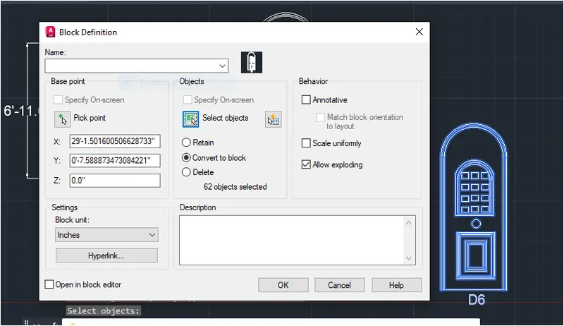
Choose Home tab>Block panel>create to start the block command.
The block defination dialog box opens.
PROCEDURE:
- OPEN AUTOCAD>
- In startup setting start from scrach select metric(meter).
- Setup limits.
- Type UN in command box nad press enter.
- Change unit type decimal and precision to 0.00 and insertion scale to milimeters.
FOR 1ST TEMPLATE:
STEP-1:
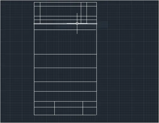
- Assume dimension to create table of template>
- In the command prompt type L to draw.
- By using line command line start the line command by clicking the line button on the draw panel on the ribbon,or by entering L and then pressing enter.
- Draw line segments by picking several random points.
- Terminate the commnad by pressing enter.Draw line segments by picking several random points.Terminate the command by pressing enter,ESC or spacebar.Press enter or spacebar to repeat the line command.
STEP-2:
- Enter all text in template which is drawed.
- In ribbon tab> Annotate > Mtline ( to draft the next)
- Assume font Arial with 70 size to make it visible.
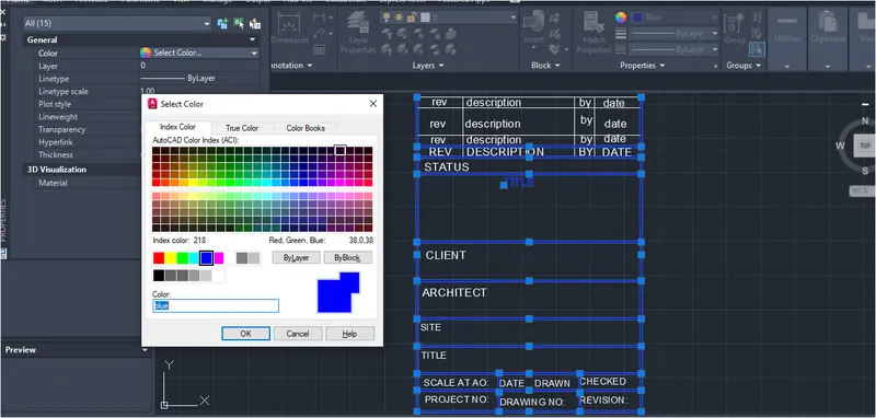
- Go to properties tab change colour ( 150 blue).
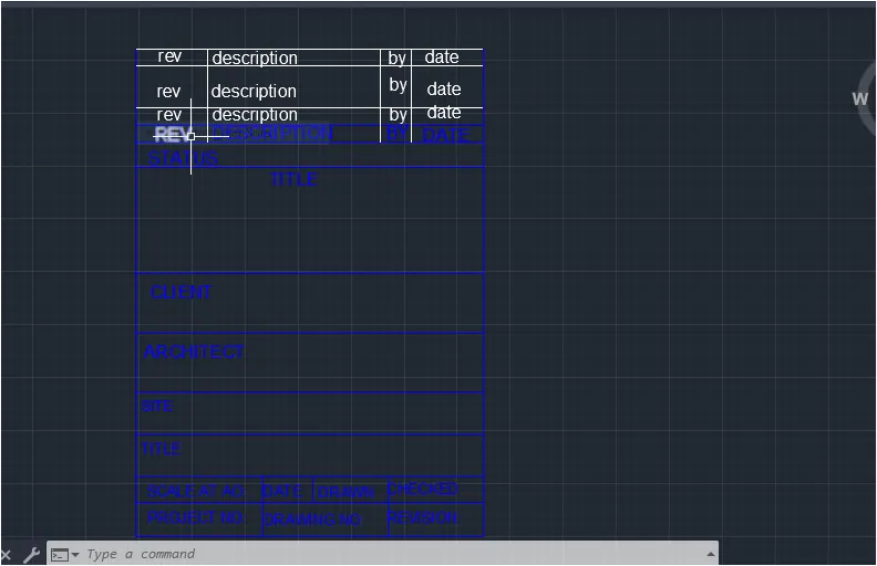
STEP-3:
- Create block
- Select object
- In ribbon bar> Block> create block and name it Custom 1- titleblock.Therefore block is created.
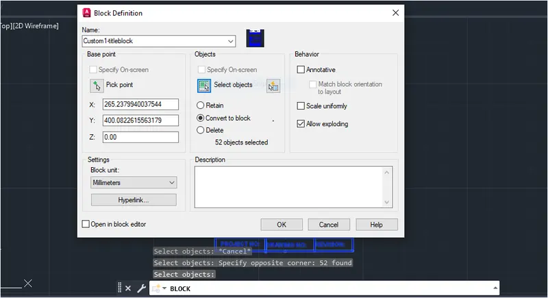
BY using insert command we can add existing block in drawing.
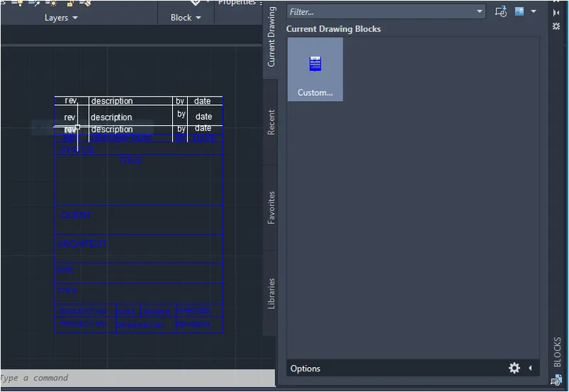
RESULT:
FOR 2nd TEMPLATE:
STEP-1:
- In command prompt type L to draw the lines and crete a template as per given.
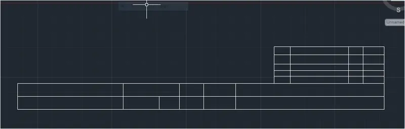
STEP-2:
- Add text
- In ribbon tab> Annotate>Mtline ( to draft the next)
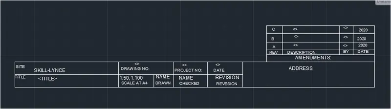
STEP-3:
- Create a block from templete.
- Block command-Choose home tab > Block panel> Create to start block command.
- The block defination dialog box opens.
- Make required setting and press enter.
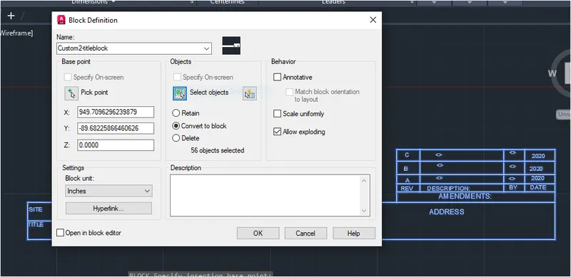
By using insert command we can add exsiting block in drawing.
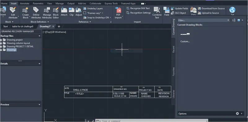
RESULT:
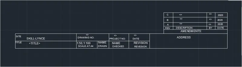
FINAL RESULT:
QUESTION-2:
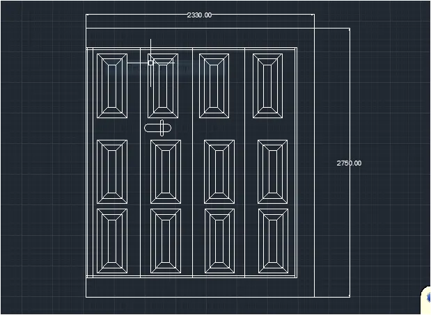
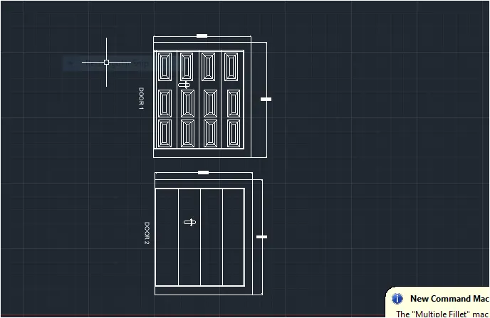
Create the doors type for warehouse as shown in the figure.You need to create each door type as per standard size or given dimensions.Create the blocks of this door type after creating them.
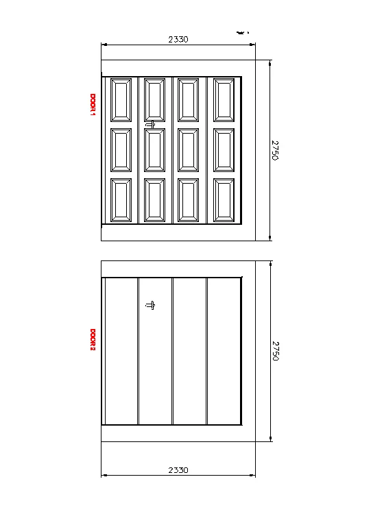
ANSWER:
AIM: To create the doors type for warehouse and to also create the block of this door them type after creating them using AUTCAD.
INTRODUCTION:
- Create door as given in figure using line offset trim, block,circle or arc command.
- LINE:- Start the line command by clicking the line command on draw panel on ribbon or by entering L and then pressing enter.Terminate the command by pressing enter ESC or spacebar .we can press enter to repeat the line command.
- REC:- By using rec command we can create recatngle.
- TRIM:- Click home tab modify panel trim.select extra lines after creating object.
- OFFSET:- We can offset any object through a point or t a specified distance.we can creates as many parallel lines and curves with the help of the offset command.
PROCEDURE:
- Open AUTOCAD
- In startup setting start from scratch select metric (meter).
- Setup limits.
- Type UN in command box and press ente.
- Change unit type decimal and precision to 0.00 and insertion scale to milimeters.
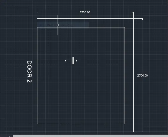
STEP-1:
CREATING DOOR BOX-
- Use rec command to create rectangle box.
- Select dimension: D
- Specify length & width 2330 and 2750.
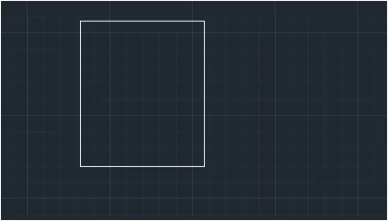
STEP-2:
OFFSET TO CREATE DOOR FRONT PANEL.
- Give offset o by assuming distance.
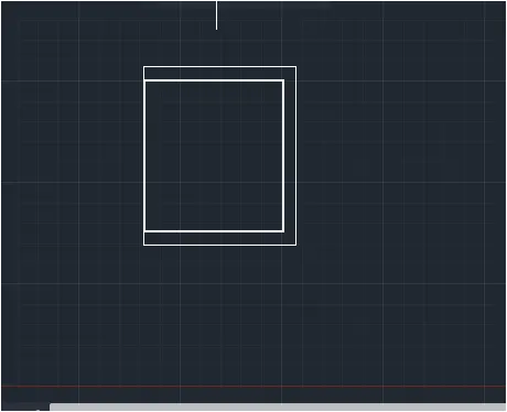
- Divide panel into 4 section by giving offset command.
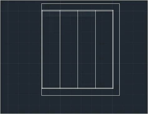
STEP-3: MAKE OBJECT
MAKE A NOTCH FOR DOOR OPENING.
- Open line command and give it to horizontal then given offset line to existing line.
- Give L line command in command tab upward with distance and given offset line to existing line.
- Give arc command > Start- center -End
- Start from 1 point of line mid point consideed as center and end or we can create half circle.
- Make object using rec,line
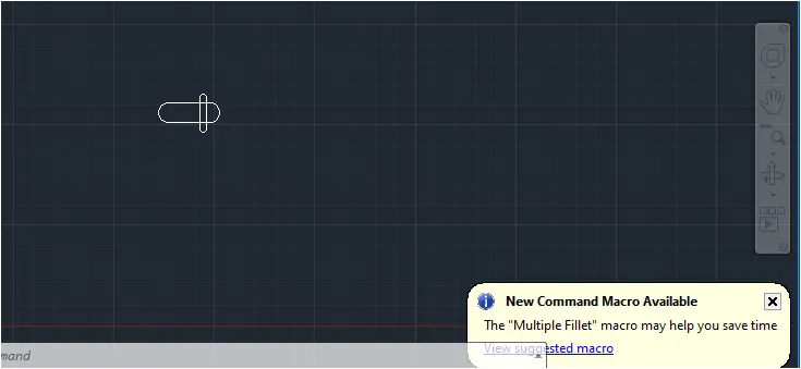
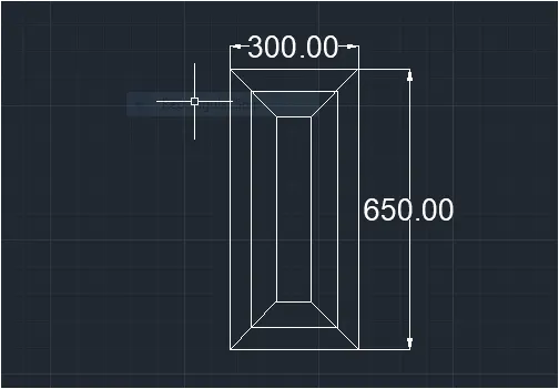
STEP-4: PLACE CREATED OBJECT
- Place oject in door panel.
- Take copy of created object and placed as per given in figure.
- In ribbon bar> dimensions ( to give the dimension of the door)
- In ribbon bar> annotation text ( to give text for door).
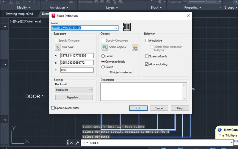
STEP-5: CREATE BLOCK.
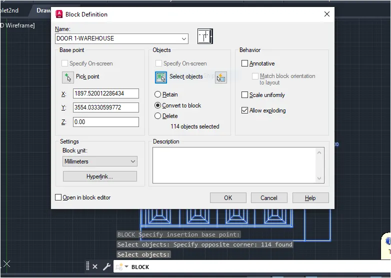
- Go to block> create block.
- Select object them make it as block.
FOR 2ND DRAWING-
STEP-1: CREATING DOOR BOX
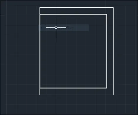
- Use rec command to create rectangle box.
- Select dimension: D
- Specify length & width 2330 and 2750
STEP-2: OFFSET TO CREATE DOOR FRONT PANEL.
- Give offset o by assuming distnace>
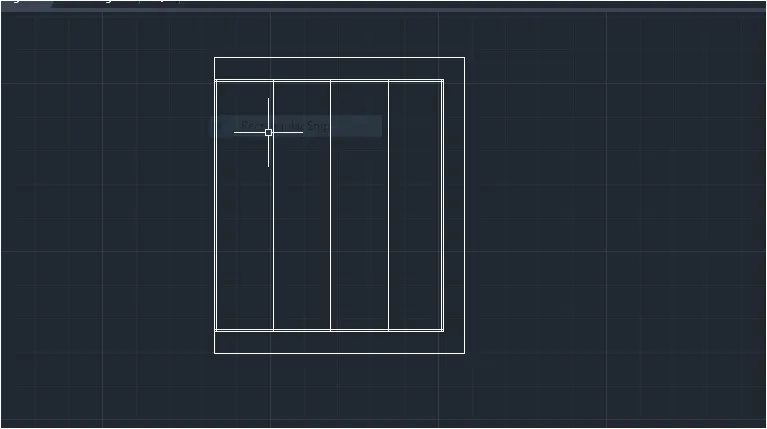
- Divide panel into 4 section by giving offset command.
STEP-3 PLACE CREATED OBJECT.
- Place object in door panel.
- Take copy of created object and placed as per given in figure.
- In ribbon bar> dimensions ( to give the dimension of the door)
- In ribbon bar > annotation text ( to gice text for door).
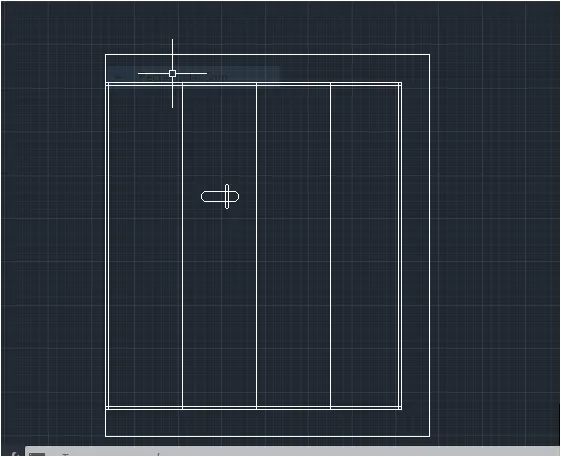
STEP-4: CREATE BLOCK
- Go to block> create block.
- Select object then make it as block.
RESULT:
QUESTION-3
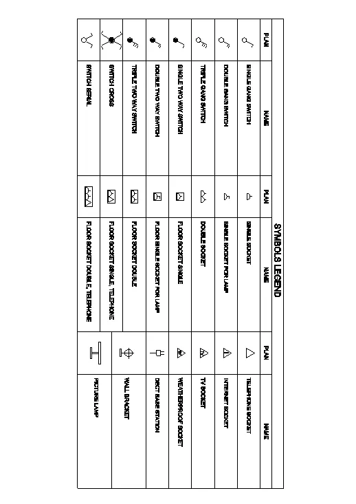
Create each symbols as a block with the name given in the legend.After creating the blocks arrange them in the legend as shown in the figure.
ANSWER:
AIM: To Create each symbols as a block with the name and arrange them legend.
- Create each electrical symbol
- Creating them as block
- Arranging them in legends.
INTRODICTION:
- The symbol legend given consist plan of electrical component along with the name of each components.
- First blocks are created using plan views and srepective names.
- Then the legned is prepared using field box command in which object and object name are selected.
PROCEDURE:
- Open AUTOCAD.
- In startup setting start from scrach select metric ( meter)
- Setup limits
- Type UN in coomand box and press entaer
- Change unit type decimal and precision to 0.00 and insertion scale to milimeters.
CREATING ELECTRICAL SYMBOLS:
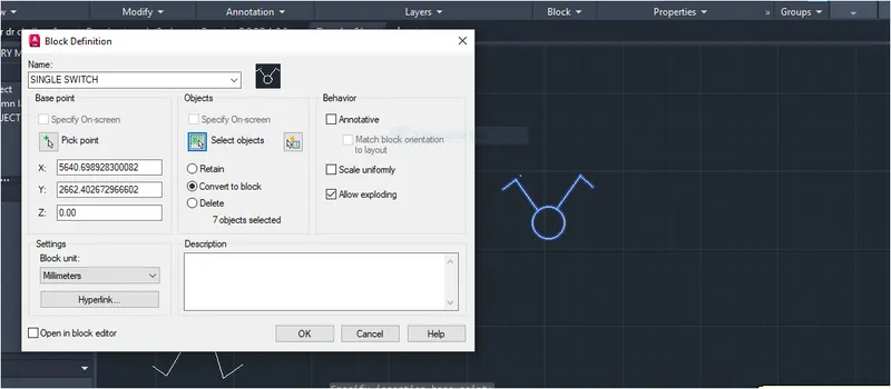
SINGLE GANG SWITCH:
STEP-1:
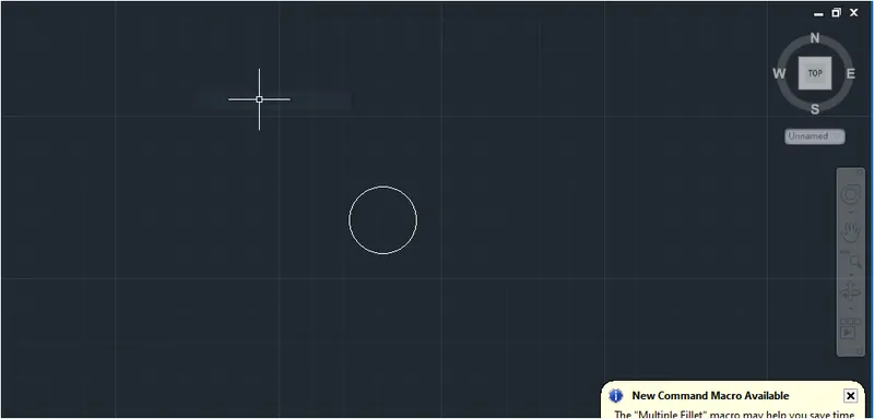
- In coomand tab type C ( circle) and press enter.
- Specify circle radius 64mm.
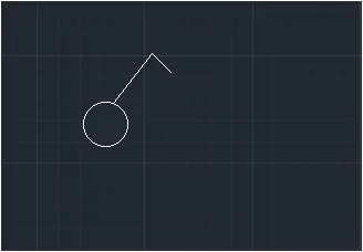
- In command tab type L( line) and press enter.
- Draw inclined line as per given.
STEP-2 CREATE BLOCK-
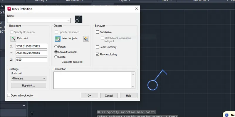
- Write block in command tab - create block- select object and pick point press enter.
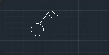
 DOUBLE GANG SWITCH:
STEP-1 :
- In command tab type C Circle and press enter.
- Specify circle radius 64mm.
- In command tab type L( line) and press enter.
- Draw inclined line as per given and draw two lines at top perpendicular to prior line.
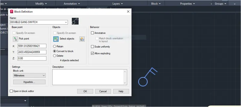
STEP-2:
- Write block in command tab - create block- select object and pick point press enter.
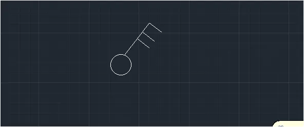
TRIPLE GANG SWITCH:
STEP-1:
- In command tab type C Circle and press enter.
- Specify circle radius 64mm.
- In command tab type L( line) and press enter.
- Draw inclined line as per given and draw three lines at top perpendicular to prior line.
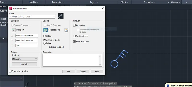
STEP-2:
- Write block in command tab - create block- select object and pick point press enter.
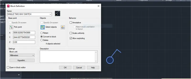
SINGLE TWO WAY SWITCH:
STEP-1:
- In command tab type C( Circle) and press enter.
- Specify circle radius 64mm
- In command tab type l ( Line) and press enetr.
- Draw inclined line as per given and draw one lines at top perpendicular to prior linbe
- Use HATCH command go to match hatch and color it as black.

STEP-2: CREATE BLOCK
- Give block command in command tab.
- Select object and give command to object
- Block is created.
 DOUBLE TWO WAY SWITCH:
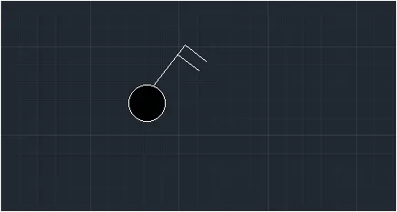
STEP-1:
- In command tab type C( Circle) and press enter.
- Specify circle radius 64mm
- In command tab type l ( Line) and press enetr.
- Draw inclined line as per given and draw two lines at top perpendicular to prior linbe
- Use HATCH command go to match hatch and color it as black.
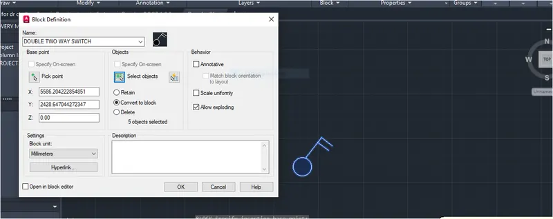
STEP-2:
- Give block command in command tab.
- Select object and give command to object
- Block is created.
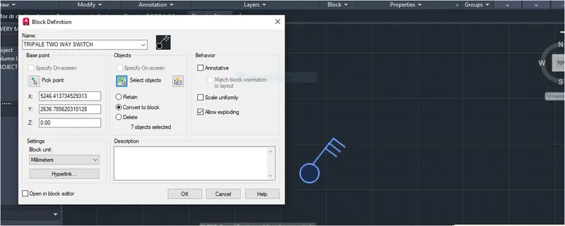
TRIPLE TWO WAY SWITCH:
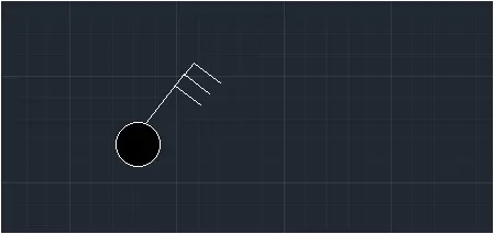
STEP-1:
- In command tab type C( Circle) and press enter.
- Specify circle radius 64mm
- In command tab type l ( Line) and press enetr.
- Draw inclined line as per given and draw three lines at top perpendicular to prior linbe
- Use HATCH command go to match hatch and color it as black.
STEP-2:
- Give block command in command tab.
- Select object and give command to object
- Block is created.
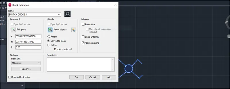
SWITCH CROSS:
STEP-1:
- Copy the above object .
- Type trim and erase 2 short lines which is parellal
- Use mirror command to mirror the line section
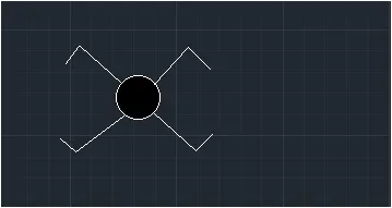
STEP-2:
- Give block command in command tab.
- Select object and give command to object
- Block is created.
SWITCH SERIAL:
STEP-1:
- Copy the above object.
- Trim the bottom lines of the circles.
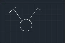
STEP-2:
- Give block command in command tab.
- Select object and give command to object
- Block is created.
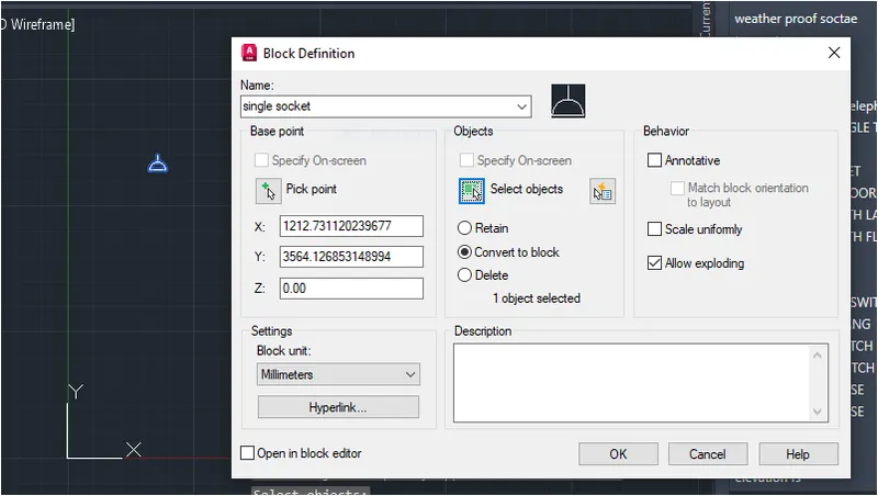
SINGLE SOCKET:
STEP-1:
- Type line command make horizontal line.
- Make semicircle using circle and then trim command.
- Mkae top line using line command.
STEP-2:
- Give block command in command tab.
- Select object and give command to object
- Block is created.
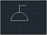
SINGLE SOCKET FOR LAMP
STEP-1:
- Copy the above object
- Type line command
- Make horizontal line to top corner of top line at right side.
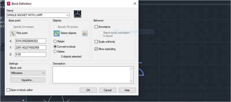
STEP-2:
- Give block command in command tab.
- Select object and give command to object
- Block is created.
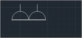
DOUBLE SOCKET :
STEP-1
- Copy the above object.
- Use mirror command and mirror the object.
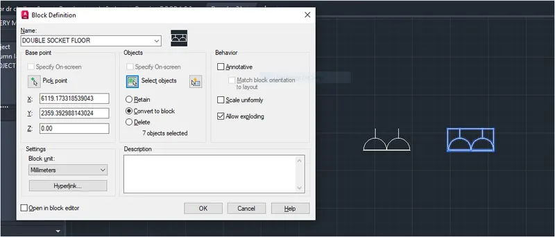
STEP-2
- Give block command in command tab.
- Select object and give command to object
- Block is created.
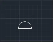
FLOOR SOCKET SINGLE:
STEP-1:
- Copy the object
- Type rec command and make rec outside the object.
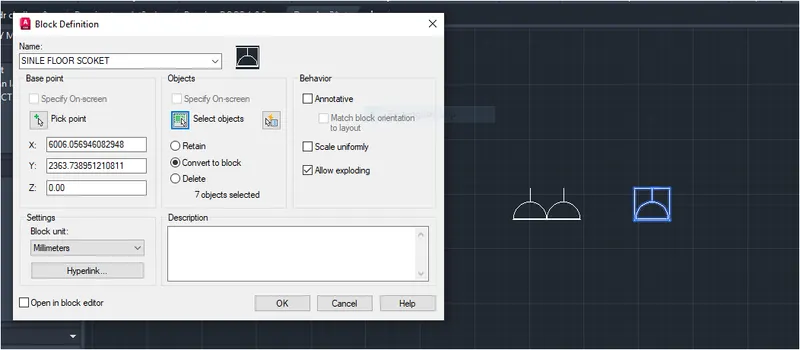
STEP-2:
- Give block command in command tab.
- Select object and give command to object
- Block is created.
FLOOR SINGLE SOCKET FOR LAMP:
STEP-1
- Copy the above object.
- Make horizontal line to top corner of top line at right side.
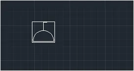
STEP-2:
- Give block command in command tab.
- Select object and give command to object
- Block is created.
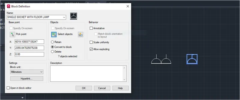
FLOOR SOCKET DOUBLE:
STEP-1:
- Copy the object.
- Type rec for rectangle and make rectangle out of it.
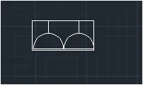
STEP-2:
- Give block command in command tab.
- Select object and give command to object
- Block is created.
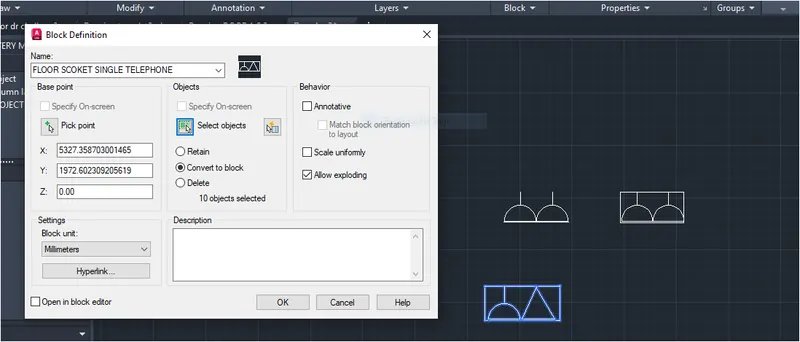
FLOOR SOCKET SINGLE,TELEPHONE:
STEP-1:
- Copy the above object.
- Erase the mirror object.
- Type line command and make triangle.
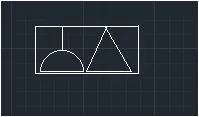
STEP-2:
- Give block command in command tab.
- Select object and give command to object
- Block is created.
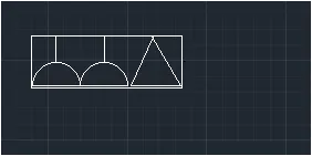
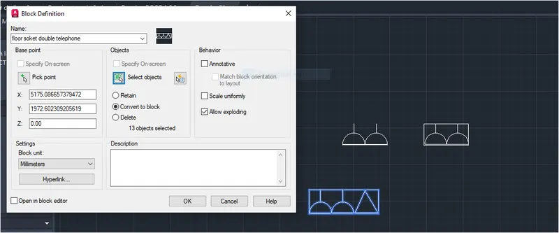
FLOOR SOCKET DOUBLE TELEPHONE:
STEP-1:
- Copy the object which has 2 semicircle digram.
- Type for line and make tringle attachtomit.
- Type rec and make rectangle out side the digram.
STEP-2:
- Give block command in command tab.
- Select object and give command to object
- Block is created.
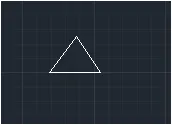
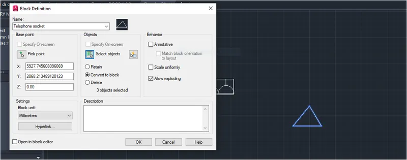
TELEPHONE SOCKET:
STEP-1:
- Type line command and make tringle out of it.
STEP-2:
- Give block command in command tab.
- Select object and give command to object
- Block is created.
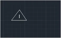
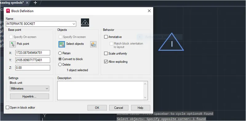
INTERNATE SOCKET:
STEP-1:
- Copy the above object
- Type attdef for attribute type text inside the tringle.
- Copy the tringle object.
- Make other fig.
STEP-2:
- Give block command in command tab.
- Select object and give command to object
- Block is created.
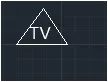
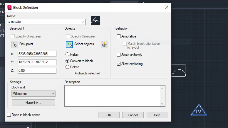
TV SCOKET:
STEP-1:
STEP-2:
- Give block command in command tab.
- Select object and give command to object
- Block is created.
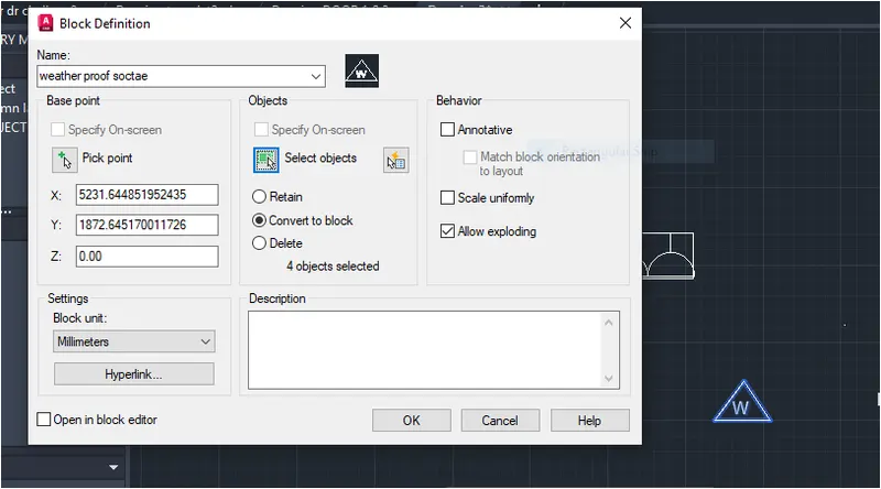
WEATHER PROOF SOCKET:
STEP-1:
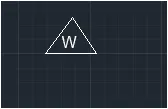
STEP-2:
- Give block command in command tab.
- Select object and give command to object
- Block is created.
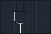
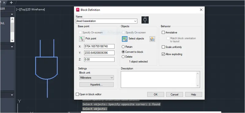
DECT BASE STATION:
STEP-1:
- Using line circle command make following fig.
STEP-2:
- Give block command in command tab.
- Select object and give command to object
- Block is created.
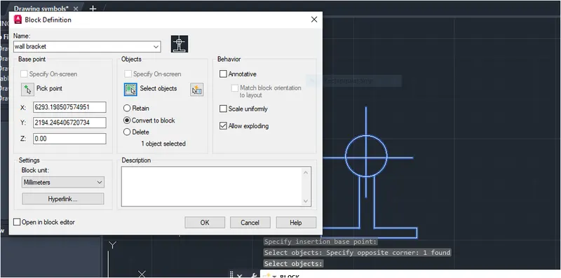
WALL BRACKET:
STEP-1:
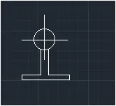
STEP-2:
- Give block command in command tab.
- Select object and give command to object
- Block is created.
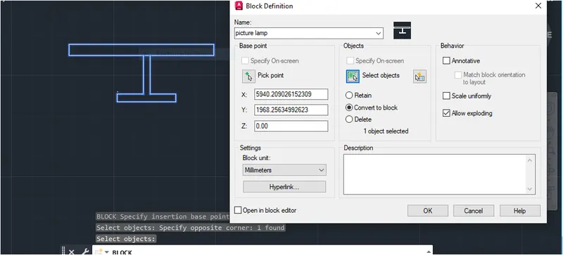
PICTURE LAMP:
STEP-1:
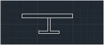
STEP-2:
- Give block command in command tab.
- Select object and give command to object
- Block is created.
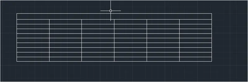
MAKE TABLE:
STEP-1:
- Using line command draw line horizontal and vertical with distance.
- Using offset command specify some distnace.
STEP-2:
- Place all the created symbols.
- Write all the text as per given use Mtext .
- Select Mtext from ribbon tab, choose font & size .
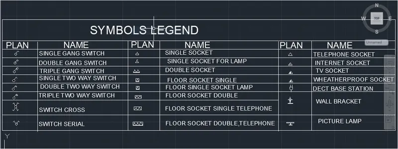
RESULT:
We created symbols and arrange it accordingly which are given in challenge question.
QUESTION-4:
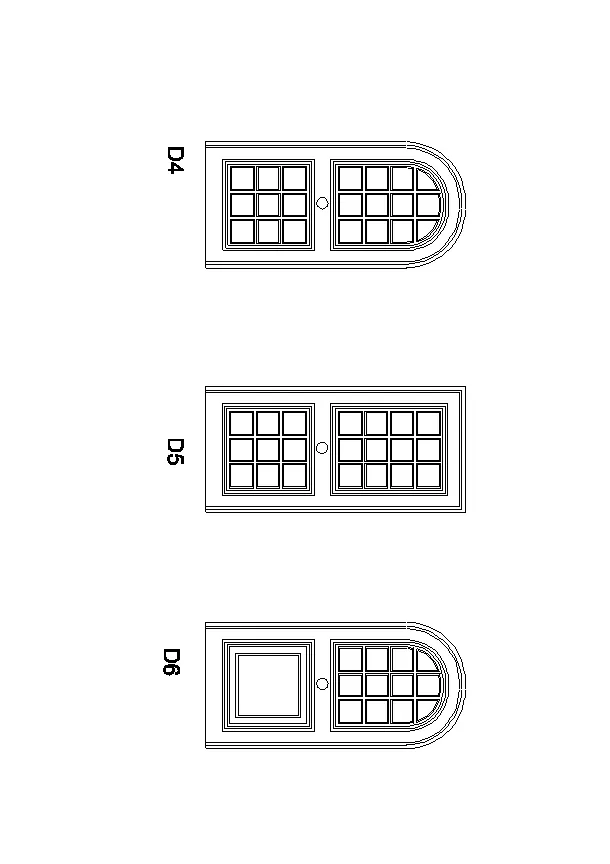
Createthe door type for residential building as ablock.Save the name of the blocks as type.Use given dimensions or assume dimensions as per industry standards.
ANSWER:
AIM: To create door type for residential building as ablock.
INTRODUCTION:
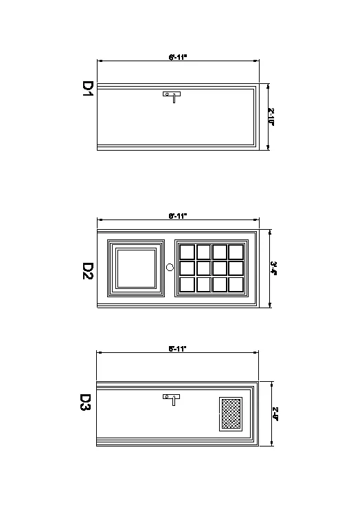
- Two door types are given both with same direction .
- First door type as projection or shapes on top of it along with door handle and door frame.
- Second door type is normal four panel double swing door with handle and door frame.
PROCEDURE:
- OPEN AUTOCAD
- In starting setting start from scrach select imperical ( feet and inche).
- Open grid and snap spacing 1'
- Turnoff adaptive grid.
- Type UN in command box and press enter.
- Change units type to decimal and precision to 1'1/16" and insertion scale to inches.
CREATING DOOR -1:
STEP-1:
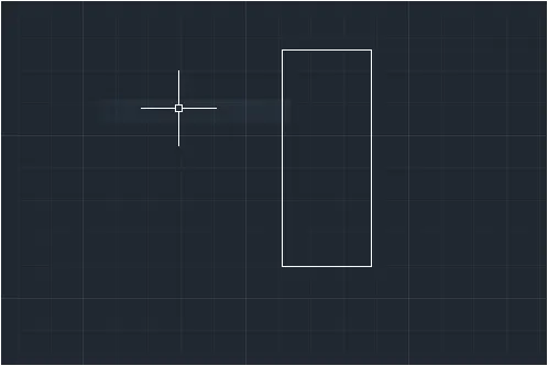
- In command tab given REC command or rec from ribbon tab.
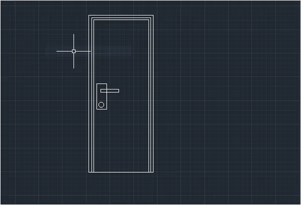
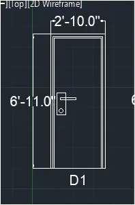
- Draw a rectangle of dimension 2'10"*6'11"
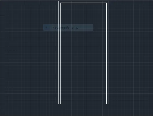
- Select rectangle drawn above and type explode and press enter.
- Select the top right and left edges and type join and press enter.
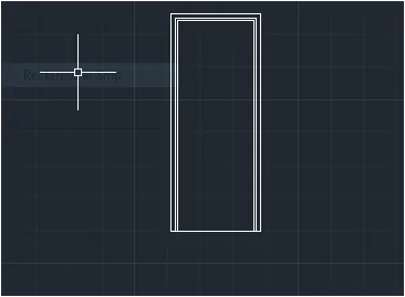
- Offset the top right and left edges to the inside of rectangle to a distance of 1.5"
- Offset the top right and left adjes to inside of rectangle to adistance of 1"
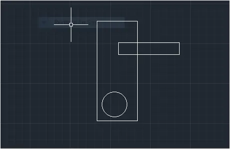
- Draw the door handle using rectnagle command and circle command as shown in fig.
Create a notch using rectangle and circle command.
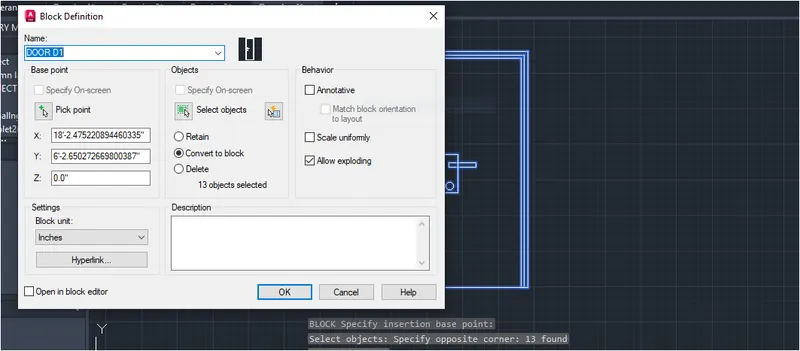
BLOCK CREATED FOR DOOR -1:
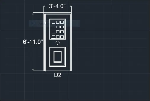
CREATING DOOR-2:
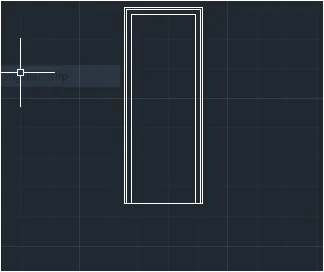
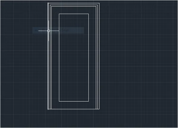
STP-1:
- In command tab give REC command or rec from ribbon tab.
- Draw a rectangle of dimension 3'4"*6'11"
- Select the rectangle drawn above and type Explode and press enter.
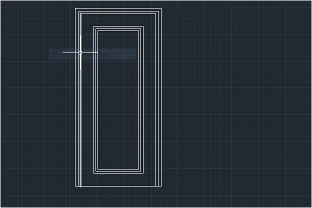
- Offset the top right and left edges to the inside of rectnagle to distance of 1.5"
- Offset the last offset pline to the inside of rectangle to adistance of 1"
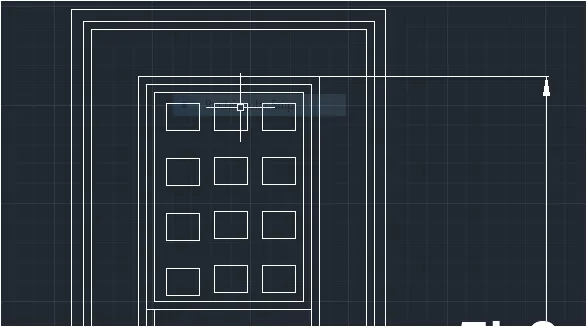
- Draw a rectangle using rectangle command at an offset of 6" fro the offset line .
- Draw the rectangle offset of 1" to the inside twice.
- Draw a rectangle array command draw four rows and three columns.
- Draw cirle just below the rectangle as shown in fig with a radius of 2.5"
- Below the circle draw a rectangle leaving 6" offset from the edges.
- Offset the rectangle inside to the distances of 1" four times3" and 1" twice.
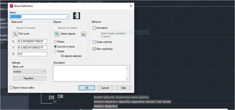
CREATING A BLOCK:
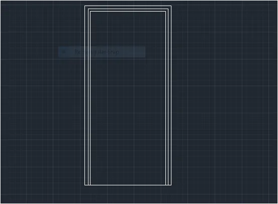
CREATING DOOR-3:
STEP-1:
- In command tab give rec command or rec from ribbon tab.
- Draw a rectangle of fimension 2'9*6'11"
- Select the rectangle drawn above and type join and press enter.
- Select the top right and left edges to the inside of rectangle to adistance of 1"
- Offset the last offset pline to the inside of rectangle to adistance of 2"
- Offset the last offset pline tothe inside of rctangle to adistance of 1"
- Offset the last offset line to the inside of rectangle to adistance of 2"
- Draw a rectangle at an offset of 4" from the edges and offset the rectangle 1" to inside .
- Hatch the inner rectangle with hach pattern NS137.
- Draw the door handle similar similar to the door type 1.
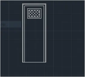
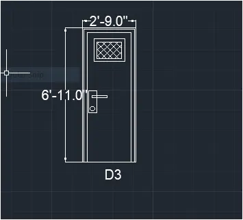
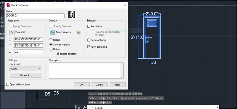
BLOCK CRETAED DOOR-3
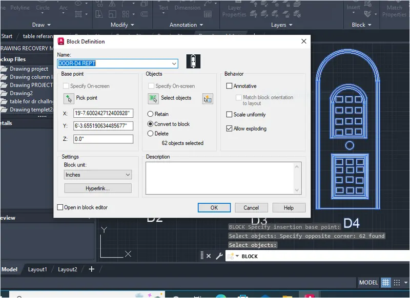
CREATING DOOR-4:
STEP-1:
- Create the door similar to door type2
- Draw a circle with diameter as e width of door
- Trim the circle bottom portion.
- Offset the circle similar to offset done for the rectangle s and trim off the extra portions as shown in the figure.
- Draw an rectangulr array of rectangles done in the top half in bottom haif reactangle too as shown in figure.
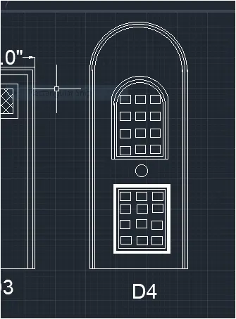
MAKE IT AS BLOCK:
CREATING DOOR-5:
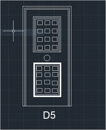
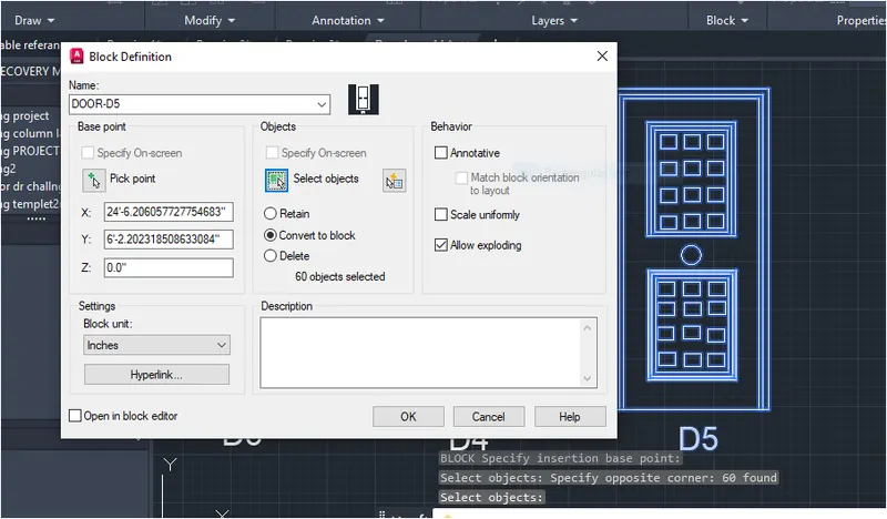
STEP-1:
- Create the door similar to door type 2.
- Draw an rectangular array of rectangles done in the top half in the bottom haif rectangle tool as shown in fig.
CREATE A BLOCK.
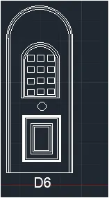
CREATING DOOR-6:
STEP-1:
- Create the door similar to door type 2.
- Draw a circle with diameter as the width of door.
- Trim the circle bottom portion.
- Offset the circle similar to offset done for the rectangles and trim off extra portions as shown in figure.
MAKE IT AS A BLOCK
RESULT:
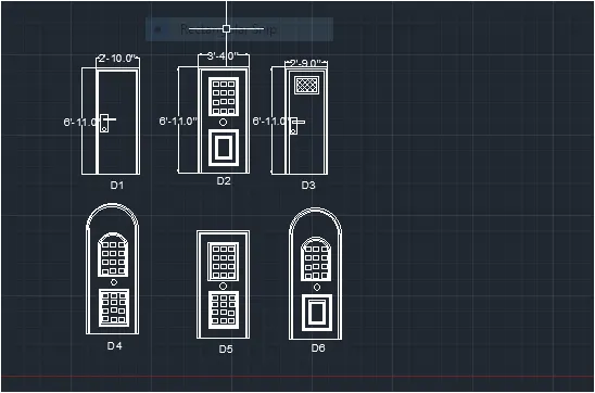
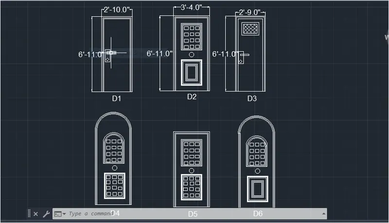
The result consist of various door type through 1to 6. layers are created for door,door handle, text and dimensions.Doors are creted through step 2 to step 6 with layres pressigned. the result is divided in to three pitures with two door types in one picture along with dimensions and text.
All dimensions mentioned are in feet and inches.
Dimensions and text are assigned using dimension layres and text layers.
QUESTION-5:
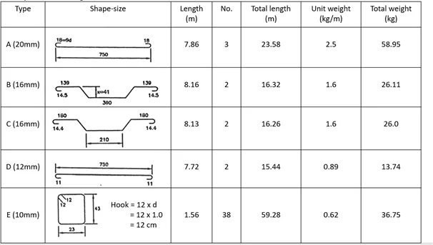
Create each shape as a block as shown in the figure .Save the block and insert them on the table as shown in the figure.
ANSWER:
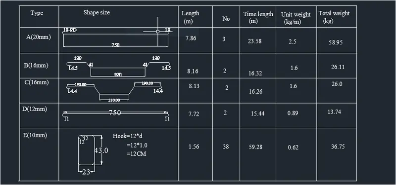
AIM: To create the blocks and reinforcement schedule as shown in figure.
INTRODUCTION:
- The given figure consists of different reinforcement detail such as type of reinforcement,number of reinforcement.and weight details of rebars.
- The aim of this question is creating the rebars using dimensions, covert these rebars to blocks and create the table containingthe data.
PROCEDURE:
OPEN AUTOCAD.
In startup settings start from scrach select metric(Meter).
Open grid and snps settings.
Type UN in command box and press enter.
Change units type to decimal and precision to 0.00 and insertionscale to milimeters.
CREATING DATA ATTRIBUTES:
STEP-1:
- Go to insert tab and click on define attribute in block defination palette or type ATTDEF in command box.
- In the popup box.
- Set mode as 'lock position'
- Set propmt as what is the type of rebar?
- Set default as A(20mm)
- Set justificationas left
- Text style as per drawing text style time NEW ROMAN and press ok.
- Place the attribute at the any point on the screen.
- For rest of attributes click on Align below previous attribute.
- Follow the same procedure for rest of the attributes.
CREATING REINFORCEMENT:
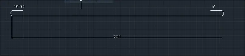
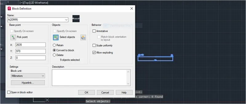
TYPE A(20MM)
STEP-1:
- Draw a line at any point on the screen to a distance of 750cm.
- Draw the semicircle at both ends for the bend of 18cm to upside.
STEP-2:
MAKE IT AS BLOCK:
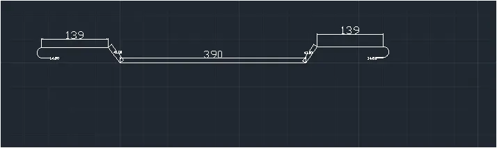
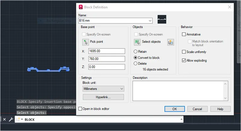
TYPE B(16MM)
STEP-1:
- Draw a line at any point on the screen to adistance of 730 cm.
- Draw the semicicrcle at both ends for the bend of 14.5 cm
- Draw aline with the centers coinciding of length 390cm.
- Move the line down to a distance of 41 cm.
- Draw the inclined shape of bar using line command as shown in figure.
STEP-2:
MAKE IT AS BLOCK
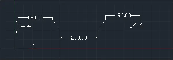
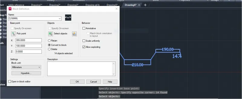
TYEP C(16MM)
STEP-1:
- Draw a line at any point on the screen to a distance of 712 cm.
- Draw the semicircle at both ends for the bend of 14.4cm.
- Draw aline with the centers coinciding of length 10cm.
- Move the line down to distance of 80cm.
- Draw the inlined shape of bar with horizontal distnace of 71.6cm using line command as shown in fig.
STEP-2
MAKE IT AS A BLOCK
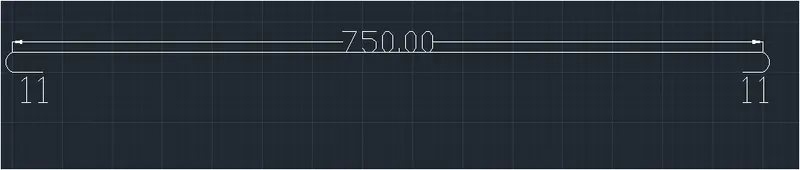
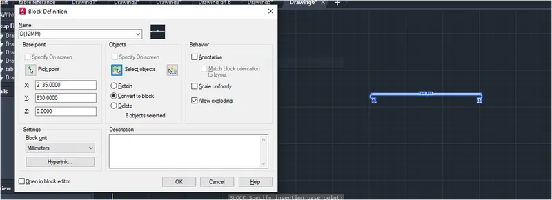
TYPE D(12MM)
STEP-1:
- Draw a line at any point on the screen to a distance of 750cm.
- Drawthe semicircle at both ends for the bend of 11cm to downside.
STEP-2:
MAKE IT AS A BLOCK
TYPE E(10MM)
STEP-1:
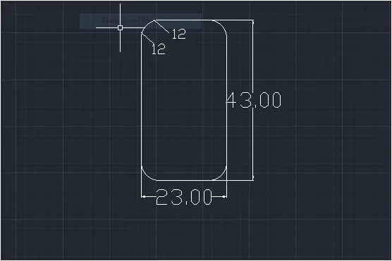
- Draw a rectangle with dimensions 230mm*430mm.
- Fillet the edges with radius of 40mm.
- Draw the extended bar fold of size 12cm.
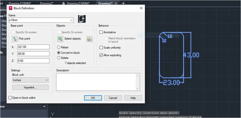
STEP-2:
MAKE IT AS A BLOCK.
CREATING TABLE;
STEP-4:
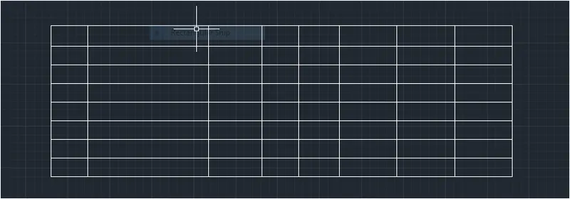
- Draw a table from the annotate tool bar.
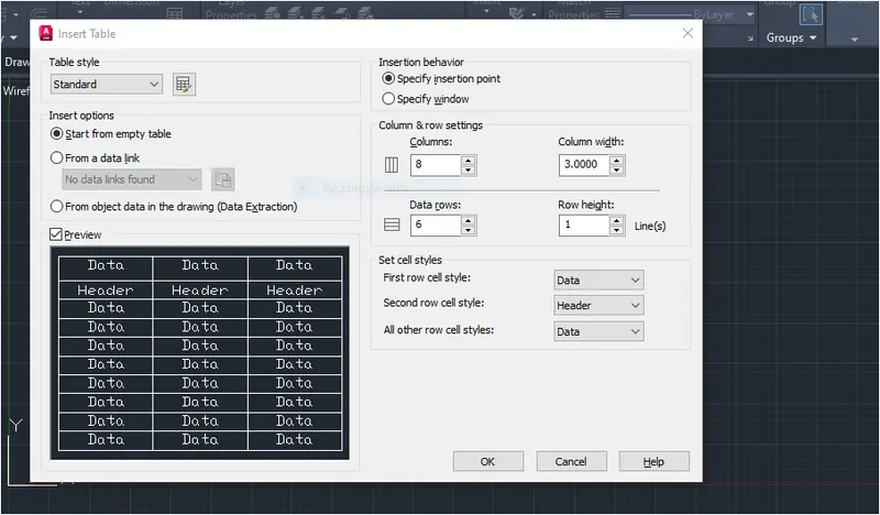
- After creating table click on second column and from table creation tool add a column to the left to add figures.
RESULT:
The result of this challange consist of rebars schedule mode from the given figure.
Create attributed are created for adding data for all types of rebars ,Reabrs are data for all types of rebars are create per the dimension in figure Attribute are copied to each of the reabr and create as ablock.
Then data is extracted from the all blocks using extract data command .Then all the data is copied to a table along with figure.
All the dimensions mentioned are in milimetres.