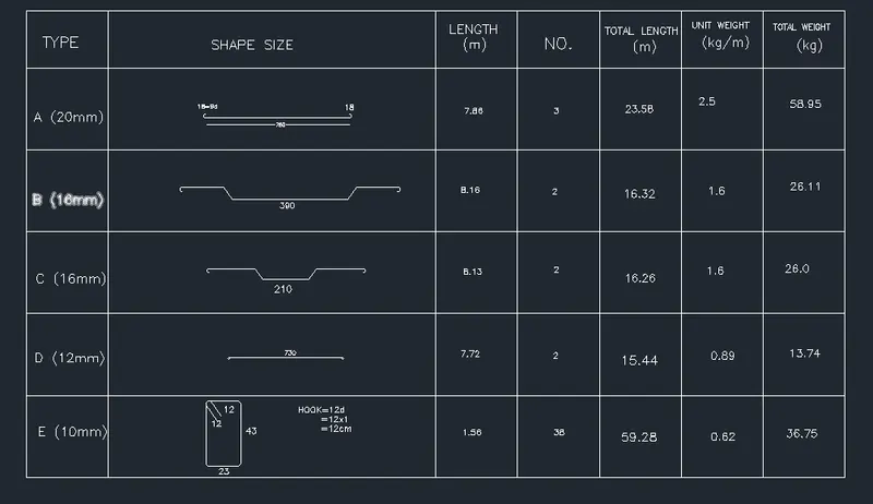
Creating Bar Bending schedule, Different Door types, and Creation of standard drawing templates using AutoCad
1. TEMPLATES
Aim
To create the given templates and convert into blocks
Procedure
- The Tables are drawn using LINE and OFFSET commands.
- The text is given using DTEXT command.
- It is editted using Manage text styles from the Annotate panel in the ribbon.
- The given text is Times New Roman.shx.
- The text is copied and pasted using COPY wherever necessary.
- It is then editted by double clicking it and typing required text.
- The colour of the lines and text is changed by selecting the required content and changing the colour from properties.
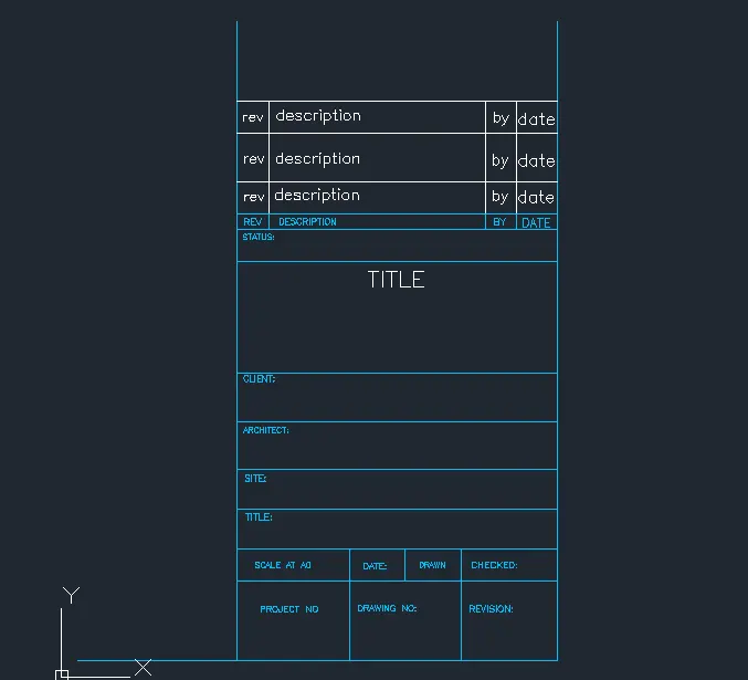
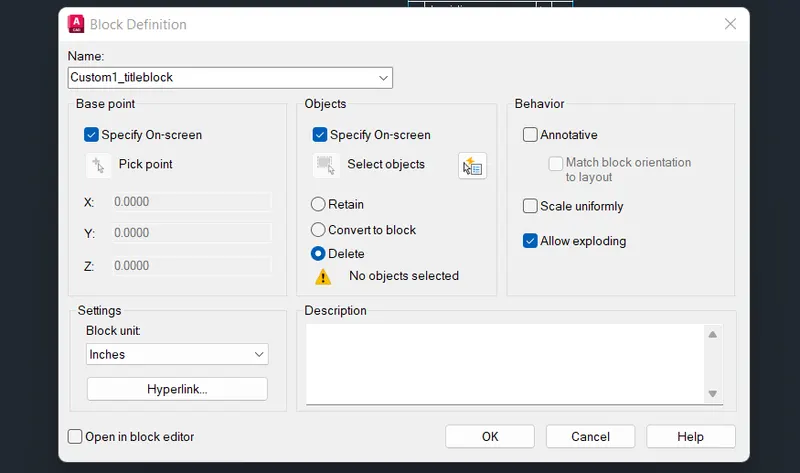
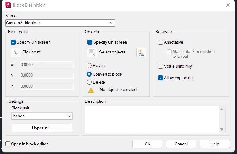
- It is then converted into a block using BLOCK command.
- The name is given as Custom1_titleblock.
- The Tables are drawn using LINE and OFFSET commands.
- The text is given using DTEXT command.
- It is editted using Manage text styles from the Annotate panel in the ribbon.
- The given text is Times New Roman.shx.
- The text is copied and pasted using COPY wherever necessary.
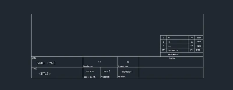
- It is then converted into a block using BLOCK command.
- The name is given as Custom2_titleblock.
Result
Thus the given templates are drawn and converted into blocks
2. Doors
Aim
To create the given door type and convert into block
Procedure
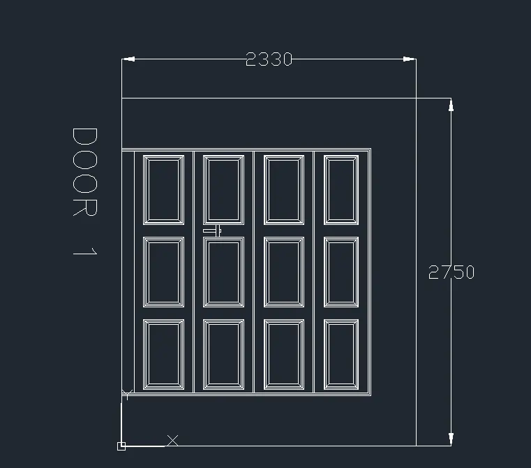
- UNITS command is given and units are set to mm.
- Using RECTANGULAR command and dimensions the outline is created.
- Using PLINE command the inner rectangle is created.
- Within the door the smaller rectangles are created using LINE and OFFSET commands.
- It is then copied using ARRAY and selecting Rectangular array option.
- The door handle is created using LINE and FILLET commands
- DImensions and text layer is created and set as current from Layer properties manager.
- The first door is then dimesioned using DIMLINEAR command.
- The second door is created by copying and pasting the first door directly below it using ORTHO button and COPY commands.
- The array of rectangles is then erased using ERASE command.
- The text is changed to DOOR 2
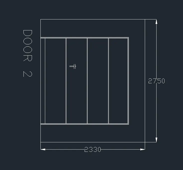
- Using Block command both the doors are converted into blocks
Result
Thus the given doors are drawn and converted into blocks
3.
Aim
To create each symbol as a block with the name given in the legend and after creating the blocks arrange them in the legend.
Procedure
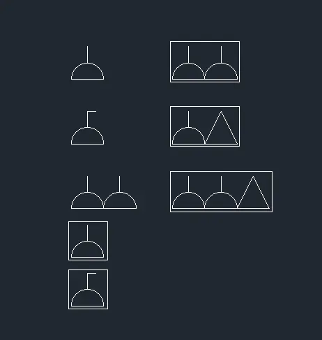
The first set of symbols are created using CIRCLE, LINE and COPY commands
Solid Hatches are used by giving HATCH command to get the black solid fill.
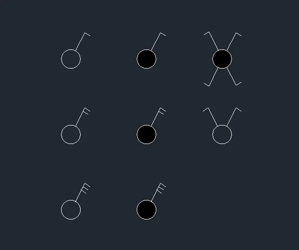
The second set of symbols are created using CIRCLE, TRIM, RECTANGULAR and LINE commands.
COPY command is used to copy repeated symbols.
The third of symbols are created using LINE, DTEXT and CIRCLE commands.
Used rectangle command where required
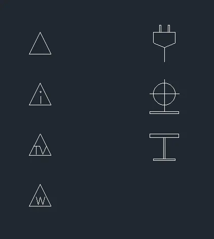
All the symbols are then converted to blocks and named as per the drawing using BLOCK command.
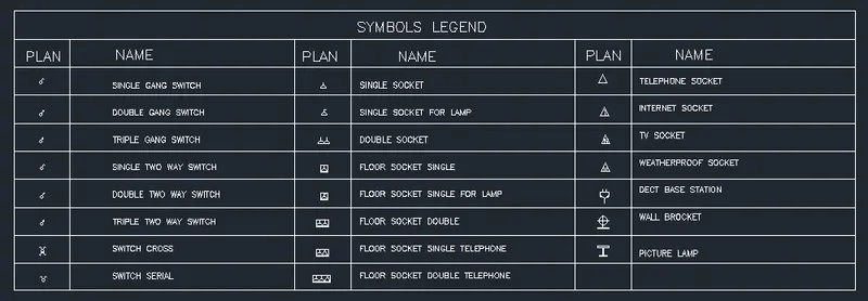
Using LINE command and TRIM command the Table is drawn.
Using INSERT command the blocks are inserted.
The headings are given using DTEXT.
Once the blocks are inserted the Field option in the Insert panel is used to get the name of the blocks.
All the blocks are inserted in the column and the names for each block are provided.
Result
All symbols are created and converted into blocks then the table column is created and the blocks are inserted as shown in the figure and the names are provided.
4.
Aim
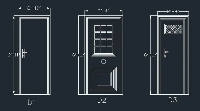
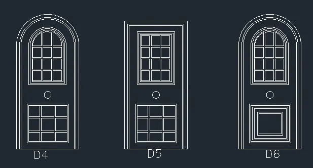
To create the door type for residential building as a block and save as type using given dimensions or assuming dimensions as per industry standards.
Procedure
New drawing is opened with Imperial default setting and Enginnering units is selected.
The doors are created as per dimensions using the RECTANGULAR, PLINE, ARC, OFFSET and TRIM commands.
Dimensions layer is created from the Layer properties manager and dimensions are given wherever required using DIMLINEAR command.
The doors are then converted into blocks using BLOCK command.
Each doors are converted into blocks
Result
The types of doors are created and converted into blocks
5.
Aim
To create the given shapes and convert into blocks then insert it in the table column as shown
Procedure
UNITS command is given and units are set to mm.
The shapes are created and using LINE, PLINE and TRIM commands.
They are dimensioned using DIMLINEAR command.
They are then converted to blocks using BLOCK command.
The table is then drawn using LINE and OFFSET commands.
The blocks are inserted using INSERT command.
DTEXT command is given and is copied and placed wherever text is necessary.
The text is then editted by double clicking it or from properties.
Result
The given shapes are created and converted into blocks and the table coumnn is created