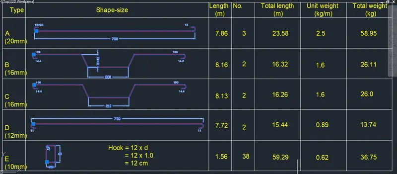
Creating Bar Bending schedule, Different Door types, and Creation of standard drawing templates using AutoCad
PROBLEM-1
AIM - TO CREATE TEMPLATES AND SAVE THE CREATED TEMLATES AS A BLOCK USING BLOCK COMMAND.
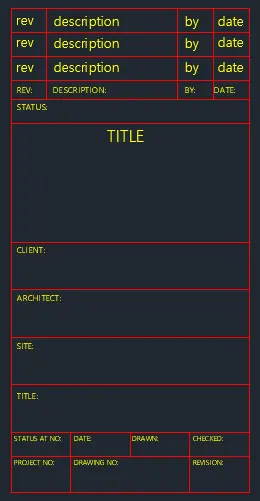
STEPS FOR CREATING TEMPLATE 1 -
- Open auto Cad and enter UN (Units command) in the command box and select type as decimal and set precision of decimal as 0
- Select X line command and draw horizontal line and vertical line.
- Trim the unwanted lines.
- Offset 1700 from vertical line and trim the unwanted lines.
- Give the following offsets in the y direction that is offset to the horizontal line.
- Offset 115.
- Offset 250.
- Offset 115 three times.
- Offset 500.
- Offset 350 two times.
- Offset 250 two times.
- Offset 200.
- Offset 220.
- Dimension- For drawing dimension using dimension tool in the ribbon.
- Text- For naming of plan use text in ribbon in that use multiline text.
- Creating layers-
- In the Layer Properties Manager, click New Layer.
- A layer name is added to the layer list.
- Enter a new layer name by typing over the highlighted layer name.
- Specify the settings and default properties of the new layer by clicking in each column
- Select color RED for layer of table.
- Creating block.
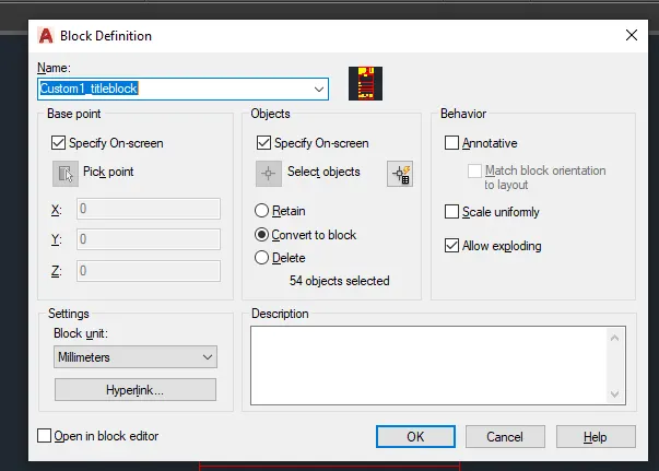
- Enter B in the command box to open block panel.
- Enter a name for the block.
- Click Select Objects, and select the graphic symbol and the attributes to include in the elevation label.
- Give block name for template as Custom1_titleblock
STEPS FOR CREATING TEMPLATE 2 -
- Open auto Cad and enter UN (Units command) in the command box and select type as decimal and set precision of decimal as
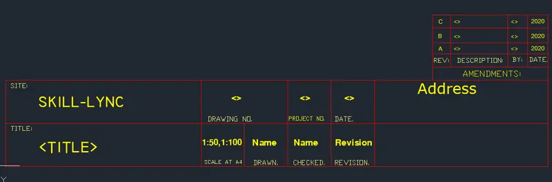
- First create the block of amendments.
- Draw a rectangle of size 170 x 150.offset 25, 50,25 ,25 ,25 in the horizontal direction that is in the y direction.
- Create another table by sing line command.
- Draw a rectangle of 800x 100. Offset 50 in the vertical direction.
- Draw the inter blocks by assuming various dimensions.
- Dimension- For drawing dimension using dimension tool in the ribbon.
- Text- For naming of plan use text in ribbon in that use multiline text.
- Creating layers -
- In the Layer Properties Manager, click New Layer.
- A layer name is added to the layer list.
- Enter a new layer name by typing over the highlighted layer name.
- Specify the settings and default properties of the new layer by clicking in each column
- Select color RED for layer of table.
- Creating block -
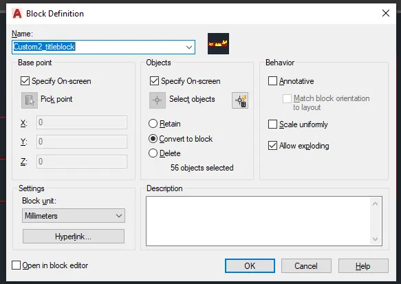
- Enter B in the command box to open block panel.
- Enter a name for the block.
- Click Select Objects, and select the graphic symbol and the attributes to include in the elevation label.
- Give block name for template as Custom2_titleblock
PROBLEM 2 -
AIM- TO DRAW THE DOOR.
- STEPS FOR DRAWING THE DOOR.
- Open auto Cad and enter UN (Units command) in the command box and select type as decimal and set precision of decimal as 0
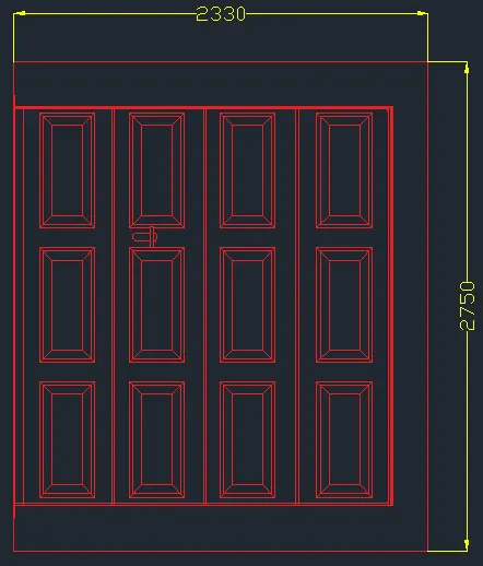
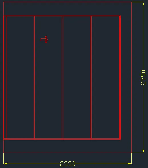
- Select line command from the ribbon and draw a line of 2330 in the horizontal direction and a line of 2750 in the vertical direction and complete the rectangle.
- Offset 583 from the vertical line of the rectangle towards he inside of the rectangle.
- Offset 583 three times.
- Again offset 5 to left and right side of each offseted line of 583 line.
- Trim the unwanted lines.
- Draw the panels as shown in the figure by taking the suitable dimensions.
- Dimension- For drawing dimension using dimension tool in the ribbon.
- Text- For naming of plan use text in ribbon in that use multiline text.
- Creating layers -
- In the Layer Properties Manager, click New Layer.
- A layer name is added to the layer list.
- Enter a new layer name by typing over the highlighted layer name.
- Specify the settings and default properties of the new layer by clicking in each column
- Select yellow colour and give the layer name as furniture.
- Creating block.
- Enter B in the command box to open block panel.
- Enter a name for the block.
- Click Select Objects, and select the graphic symbol and the attributes to include in the elevation label.
- Give block name as door_123
PROBLEM NO 3-
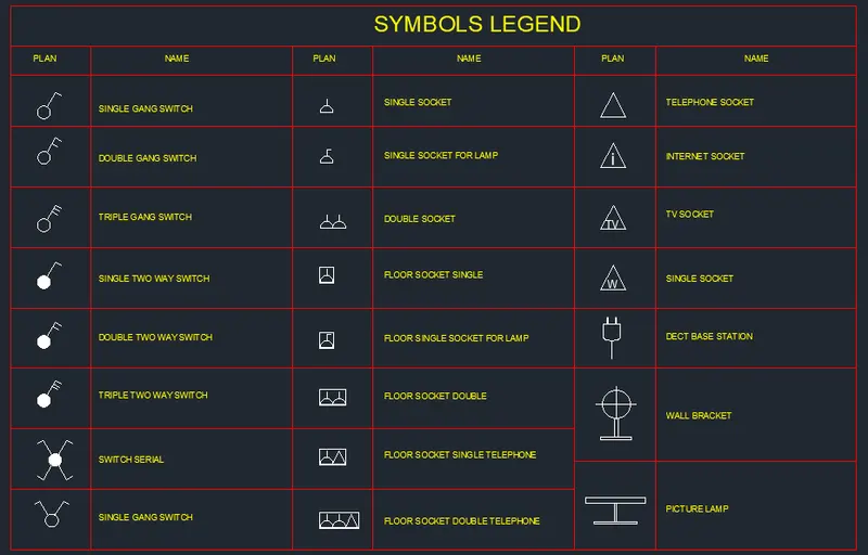
AIM- TO CREATE A SYMBOL LEGEND AND SAVE IT AS A BLOCK.
- STEPS FOR DRAWING LEGEND -
- Open auto Cad and enter UN (Units command) in the command box and select type as decimal and set precision of decimal as 0
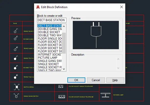
- Select line command from the ribbon and draw a line of 390 in the horizontal direction and a line of 200 in the vertical direction and complete the rectangle.
- Give offsets as follows in the X direction.
- Offset 35.
- Offset 95.
- Offset 35.
- Offset 95.
- Offset 35.
- Offset 95.
- Give the offsets as follows in the Y direction.
- Offset 10.
- Offset 10.
- Offset 20 for 8 times t complete the table.
- Draw the electrical fittings as shown in the table by using the line and various other tools.
- Dimension- For drawing dimension using dimension tool in the ribbon.
- Text- For naming of plan use text in ribbon in that use multiline text.
- Creating layers -
- In the Layer Properties Manager, click New Layer.
- A layer name is added to the layer list.
- Enter a new layer name by typing over the highlighted layer name.
- Specify the settings and default properties of the new layer by clicking in each column
- Select color RED for table and color 30 for the electrical fittings.
- Creating block.
- Enter B in the command box to open block panel.
- Enter a name for the block.
- Click Select Objects, and select the graphic symbol and the attributes to include in the elevation label.
- Give block name as symbol legend.
PROBLEM- 4
AIM- TO DRAW THE VARIOUS TYPES OF DOORS.
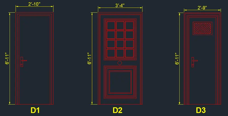
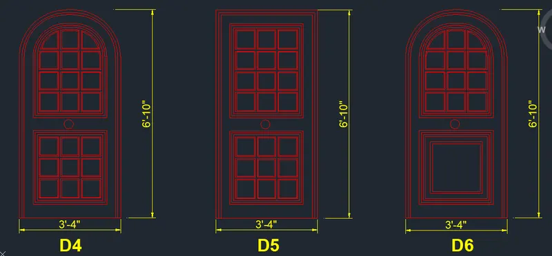
- STEPS FOR DRAWING THE DOORS D1, D2, D3, D4, D5, D6.
- Line command is used fir drawing the doors of various sizes.
- Door D1, D2, D3 has same height of 6’-11’.
- Width of door D1 is 2’-10’’, width of door D2 is 3’-4’’, width of door D3 is 2’-9’’.
- Width and height of door D4, D5, D6 is assumed as width as 3’4’’ and height as 6’-10’’
- Dimension- For drawing dimension using dimension tool in the ribbon.
- Text- For naming of plan use text in ribbon in that use multiline text.
- Creating layers-
- In the Layer Properties Manager, click New Layer.
- A layer name is added to the layer list.
- Enter a new layer name by typing over the highlighted layer name.
- Specify the settings and default properties of the new layer by clicking in each column
- Select RED color for furnitre
- Creating block.
- Enter B in the command box to open block panel.
- Enter a name for the block.
- Click Select Objects, and select the graphic symbol and the attributes to include in the elevation label.
- Give block name as D1 D2 D3 D4 D5 AND D6.
PROBLEM 5-
AIM- TO CREATE A BAR BENDING SCHEDULE AS SHOWN IN THE FIGURE.
- STEPS FOR DRAWING THE BAR BENDING SCHEDULE.
- Open auto Cad and enter UN (Units command) in the command box and select type as decimal and set precision of decimal as 0
- Select line command from the ribbon and draw a line OF 2550 in the X direction and a line of 1100 in the Y direction.
- Give offsets as follows in the X direction.
- Offset 150
- Offset 1200
- Offset 150.
- Offset 150.
- Offset 300 for 3 times.
- Give the offsets as follows in the Y direction.
- Offset 100
- Offset 200 for 5 times and complete the table
- Trim the unwanted lines.
- Line command is used to draw the reinforcement shown in the table in the desired way.
- Dimension- For drawing dimension using dimension tool in the ribbon.
- Text- For naming of plan use text in ribbon in that use multiline text.
- Creating layers -
- In the Layer Properties Manager, click New Layer.
- A layer name is added to the layer list.
- Enter a new layer name by typing over the highlighted layer name.
- Specify the settings and default properties of the new layer by clicking in each column
- Select RED color for reinforcement and color WHITE for table
- Creating block.
- Enter B in the command box to open block panel.
- Enter a name for the block.
- Click Select Objects, and select the graphic symbol and the attributes to include in the elevation label.
- Give block name as bar bending schedule