Creating Bar Bending schedule, Different Door types, and Creation of standard drawing templates using AutoCad
Introduction: Autocad is a commercial Computer Aided Design(CAD), It is marked and developed as Autodesk. It was first released on december 1982. Autocad derived from a program, which was beganed in 1977 and then released in 1979 called as Interact CAD, and also called in early documents od autocad as microCAD, Auto desk cofounder was Michael Riddle.
The first version of cad was released in december 1982 and was supported on CP/M-80 computers, By march 1986 Aotocad has became most uniquitous cad program worldwide. The file format of autocad was .dwg, and its interchange file format to DXF, have become a standard. Autocad was included support for .dwf, a format developed and promoted by Autodesk, for publishing CAD date. In year 2022 the Autocad 36th major version was released and the 12th consecutive year of Autocad foe Mac.
CAD is a technology which replaces manual drawing with automated process, if you are a drafter, desingner, architect or engineer you have been used 2D or 3D CAD programs i.e., Autocad or Autocad LT software. Autocad helps you in draft construction documentation, explore ideas for design, viaualise concepts through photorealistic renderings and gives how a design performs in real world.
Autocad mailnly used by industries, architects, engineers, city planners, project managers, graphic designers and other professionals.
1. Aim: To create the given Templates using Autocad and creating Blocks
Steps:
1.Open new file in Autocad 2023, Type UNITS, use decimal and take millimeters
2. Then LIMITS, Limits of lower left corner give (0,0) and limits of upper right corner (1000,1000)
3. Taken paper size as A2, Draw the Rectangle of 420X594mm

4. Select the rectangle and Explode
Then Offset the top horizontal line in downward direction by a distances of 30, 40, 30, 25, 130, 60, 60, 50, 50 and 35
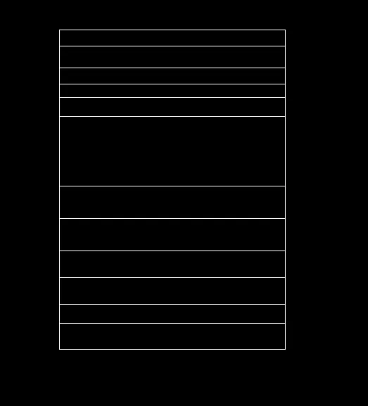
5. Divide the Rows by using Line command as per required
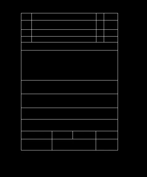
6. Using Text write the required text and font style used is Times News Roman Greek and font size as 10
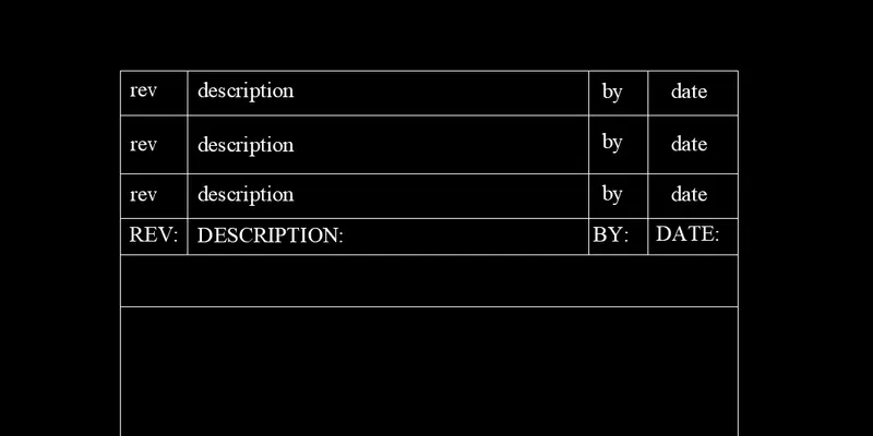
7. After writing the required Text and change the colour as per required
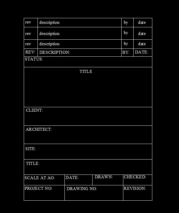
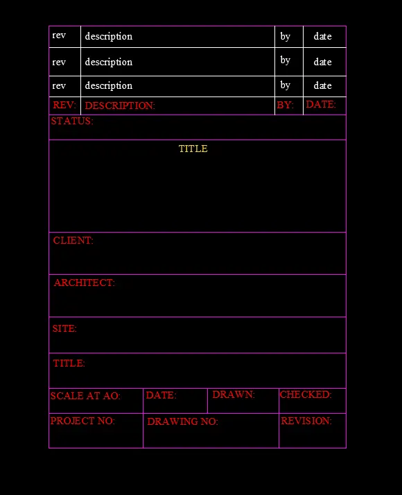
8.Select the Template and type Block and name it as Custom1_titleblock
Template 2:
1. Taken paper size as A4, Draw the Rectangle of 210X297mm
2. Offset the bottom horizontal line in upward direction by 20 and 20, using Line command draw the required lines
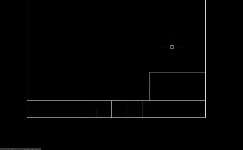
3. Draw the required lines using line command
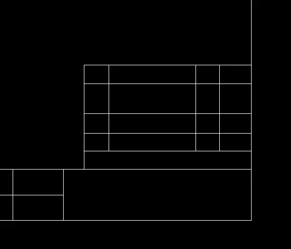
Using Text write the required text and font style used is Times News Roman Greek and font size as 5 and 2.5
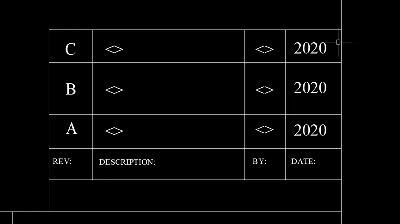
4. Using Text write the required text and font style used is Times News Roman Greek and font size as 2.5
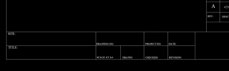
5.Type ATT or ATTDEF then the dialogue box opens and write the question at Tag and question= at Prompt and then the Answer at Default, similarly write where required
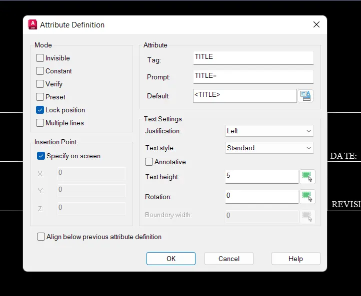
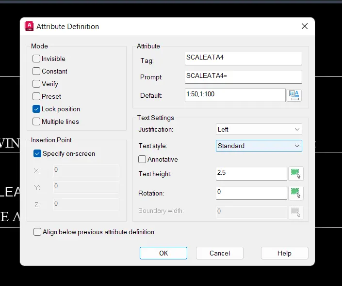
6. After creating the attributes, we get
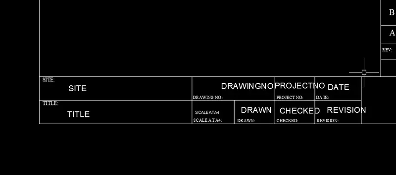
7. Now select the template and type Block and name it as Custom_2titleblock
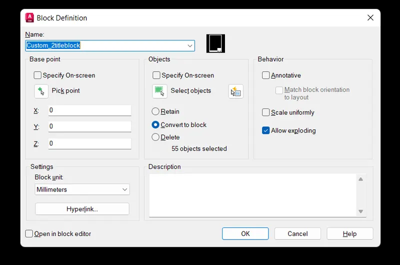
8. After creating block we get, this dialogue box and then click Ok
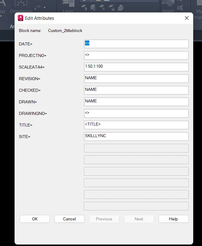
9. We get the required text in the Template
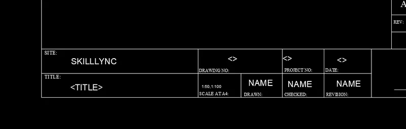
10.The required Template
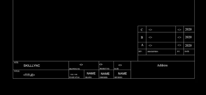
2. Aim: To create the given Doors using Autocad software
Steps:
1.Open new file in Autocad 2023, Type UNITS, use decimal and take millimeters
2. Then LIMITS, Limits of lower left corner give (0,0) and limits of upper right corner (10000,10000)
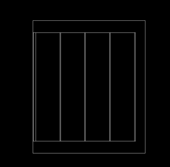
3.Take Line command and draw the line first point as (0,0) and then (@2330,0) (@0,2750) (@-2330,0) (@0,-2750)
and Offset the top and bottom horizontal in inward direction by 250 and offset the right vertical line by 200
Offset the left vertical line by in right direction by a distance of 10,50,500,15,500,15,500,15,500
and then Trim the extra lines
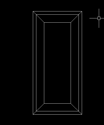
4. To draw this use Rectangle command and draw rectangle of size 310X650
And using offset, offset the rectangle in inward direction by 20 and then 50
Then using Line command join the corners
5. Place the rectangles such that they are at 90mm from vertical and 35 mm from horizontal line, using offset offset the left vertical line by 90 and top horizontal line by 35 and copy that and place at the intersection of these lines and delete the reference lines
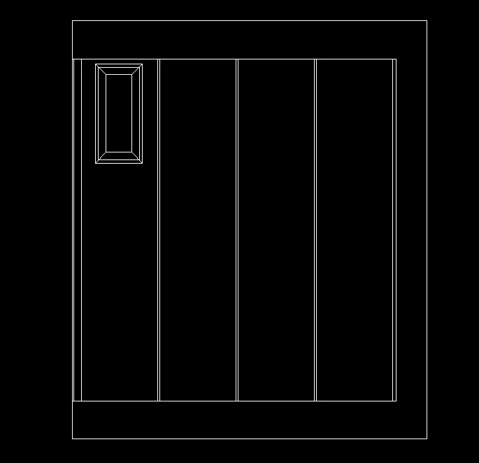
6. Using Array command select the rectangles and give No.of Columns as 4 and distance between columns is 500
and No.of Rows as 3 and distance between them is -760
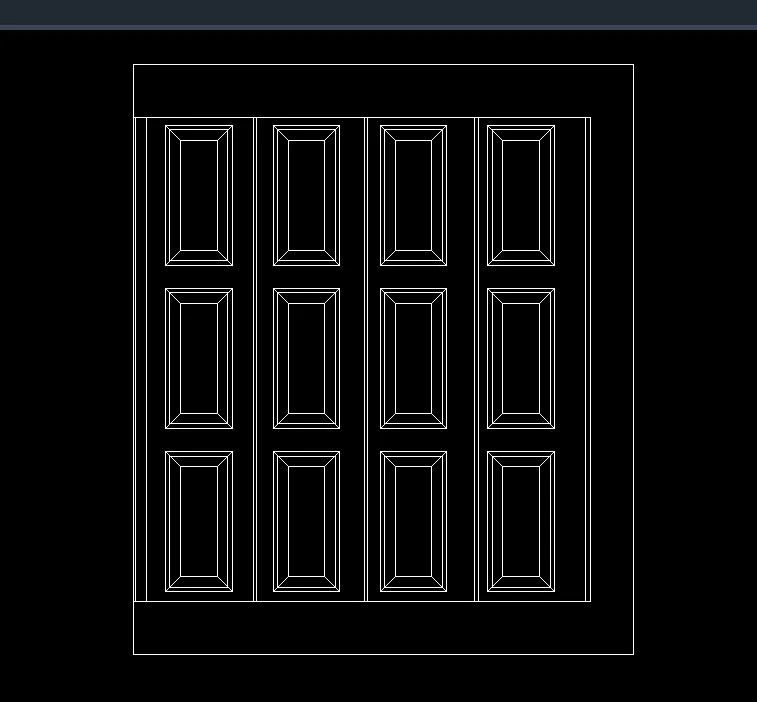
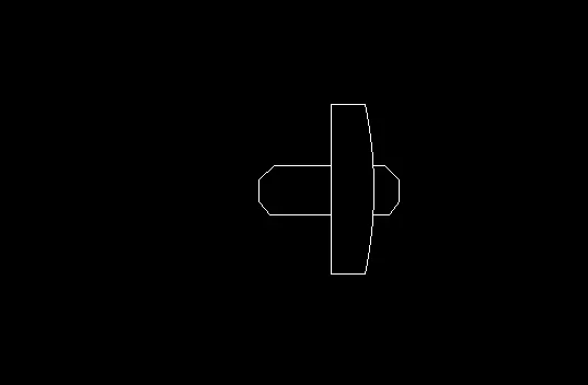
7. Create the handle using Line command and arc and copy to the door
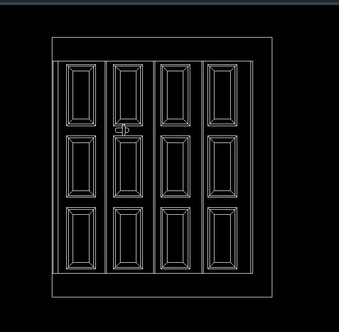
8. Offset the right inner vertical line by 2.5,2.5,5,2.5 snd 2.5 and again offset the top and bottom inner horizontal lines by 5,10 in inward direction
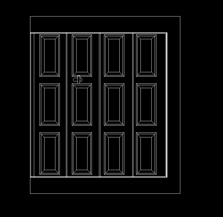
9. Provide the text and dimension, use Text style is Times New Roman Greek and font size 150, to modify dimensions tyoe DST
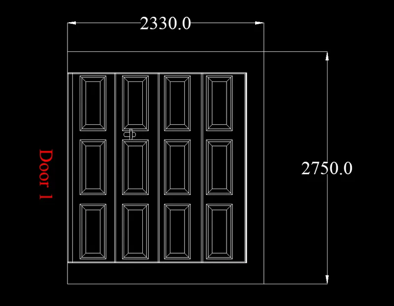
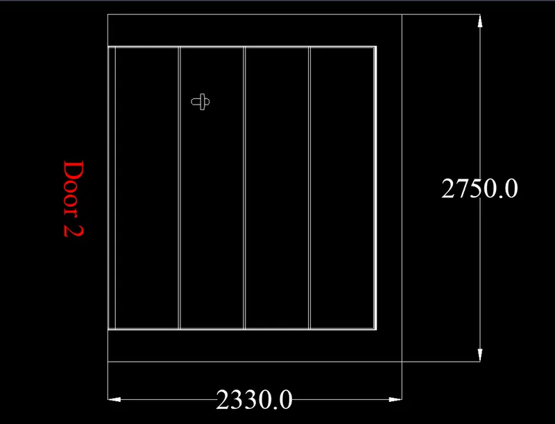
Door 2:
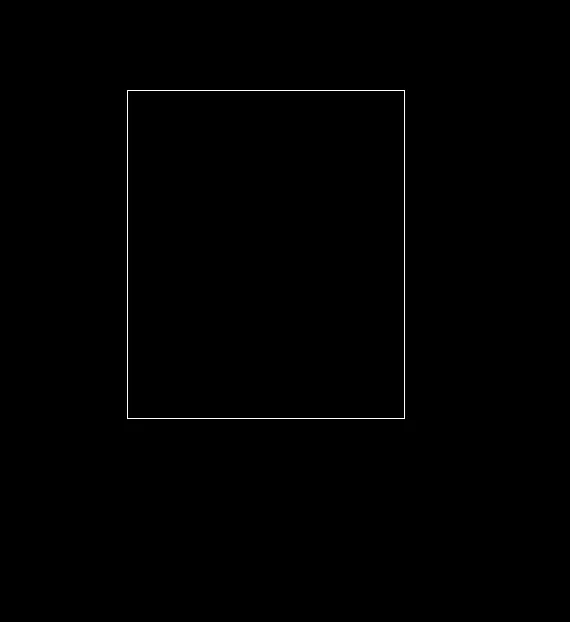
1.Take Line command and draw the line first point as (0,0) and then (@2330,0) (@0,2750) (@-2330,0) (@0,-2750)
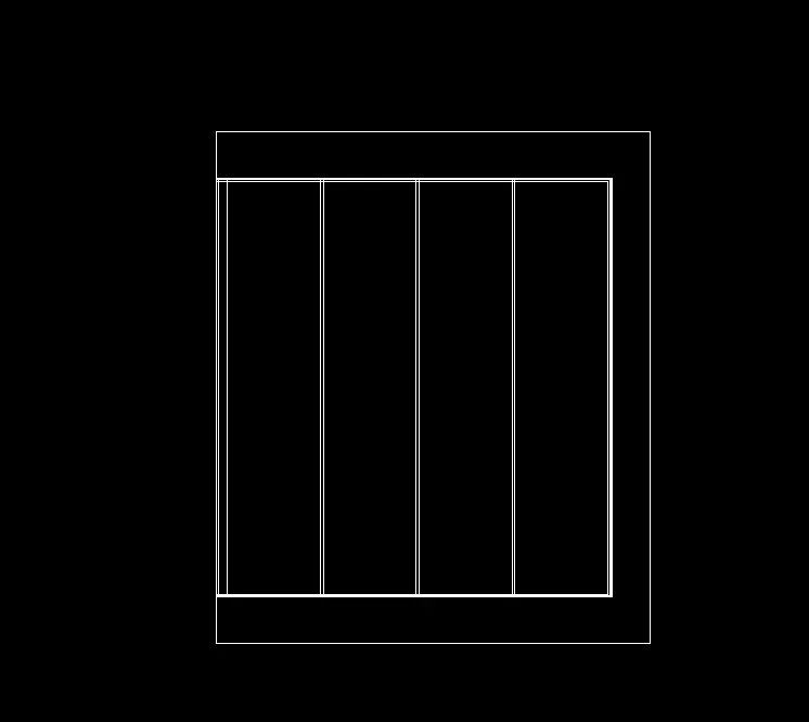
2.Offset the top and bottom horizontal in inward direction by 250 and offset the right vertical line by 200
Offset the left vertical line by in right direction by a distance of 10,50,500,15,500,15,500,15,500
and then Trim the extra lines
3. Offset the right inner vertical line by 2.5,2.5,5,2.5 snd 2.5 and again offset the top and bottom inner horizontal lines by 5,10 in inward direction
4. Place the handle such that it at a distance of 620 from left vertical line and 400 from top horizontal line draw reference lines using offset and place handle at that intersection and delete the ref lines
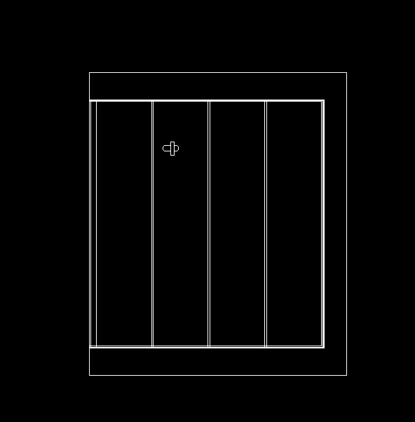
5. Provide the text and dimension, use Text style is Times New Roman Greek and font size 150, to modify dimensions tyoe DST
3. Aim: To create each given symbol as a block with the name given in the legend, and then blocks are arranged in the legend as given in the Figure. using Autocad
Steps:
1.Open new file in Autocad 2023, Type UNITS, use decimal and take millimeters
2. Then LIMITS, Limits of lower left corner give (0,0) and limits of upper right corner (100,100)
3.Create the cirle of 0.2 radius and draw a line at 60 degree and draw another small line perpendicular to previous line
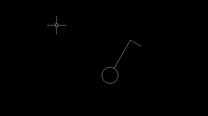
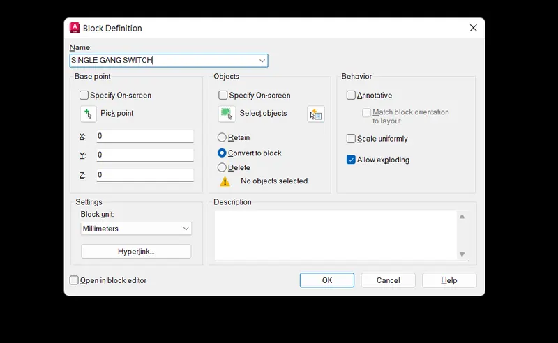
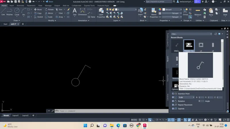
Select the object and type Block and give name as SINGLE GANG SWITCH and can be used any where in the drawing by using Insert command
4. Draw the symbol using line and circle command, Create the cirle of 0.2 radius and draw a line at 60 degree and draw another small lines perpendicular to previous line

Select the object and type Block and give name as DOUBLE GANG SWITCH and can be used any where in the drawing by using Insert command
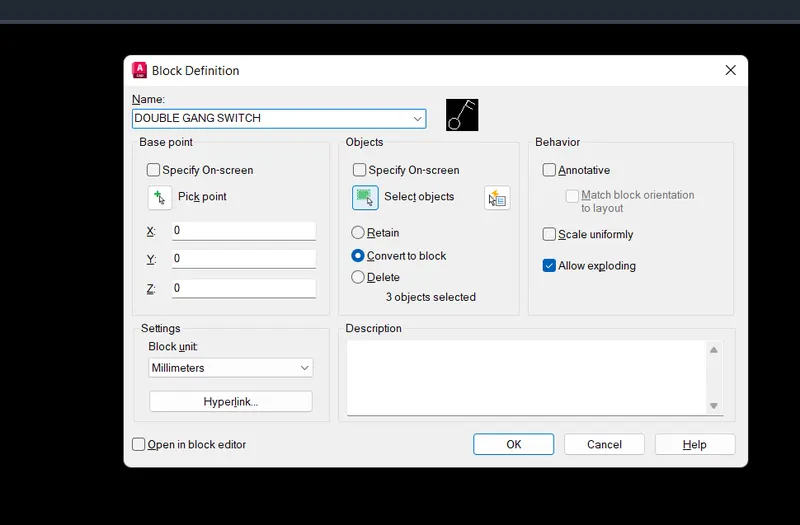
5.Draw the symbol using line and circle command, Create the cirle of 0.2 radius and draw a line at 60 degree and draw another small lines perpendicular to previous line

Select the object and type Block and give name as DOUBLE GANG SWITCH and can be used any where in the drawing by using Insert command
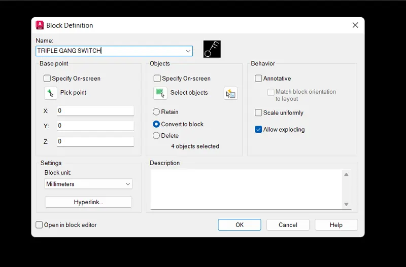
6. Draw the symbol using line and circle command, Create the cirle of 0.2 radius and draw a line at 60 degree and draw another small line perpendicular to previous line and offset the circle in inward direction by 0.05 and Hatch inside the circle

Select the object and type Block and give name as SINGLE TWO WAY SWITCH and can be used any where in the drawing by using Insert command
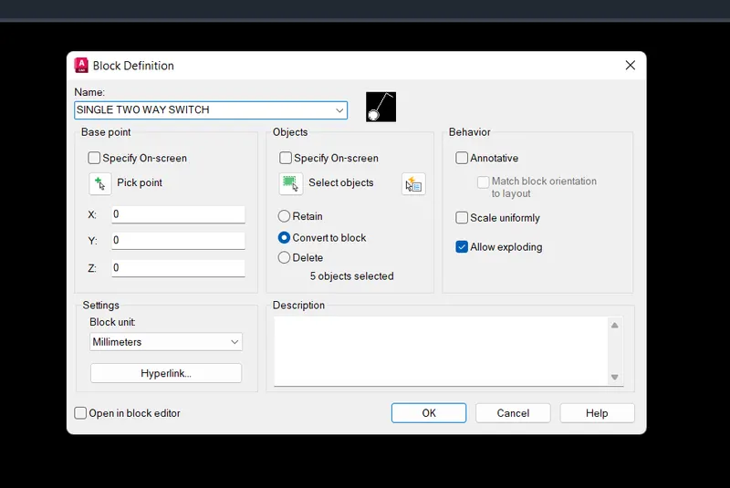
7.Draw the symbol using line and circle command, Create the cirle of 0.2 radius and draw a line at 60 degree and draw another small lines perpendicular to previous line and offset the circle in inward direction by 0.05 and Hatch inside the circle

Select the object and type Block and give name as DOUBLE TWO WAY SWITCH and can be used any where in the drawing by using Insert command
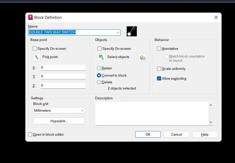
8.Draw the symbol using line and circle command, Create the cirle of 0.2 radius and draw a line at 60 degree and draw another small lines perpendicular to previous line and offset the circle in inward direction by 0.05 and Hatch inside the circle

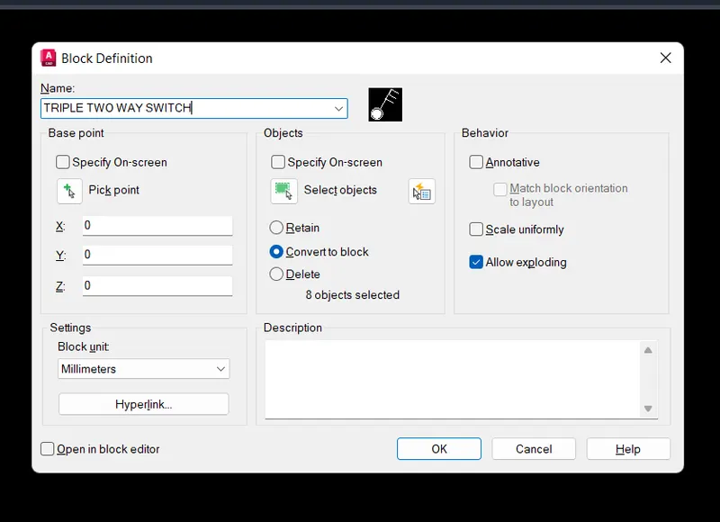
Select the object and type Block and give name as TRIPLE TWO WAY SWITCH and can be used any where in the drawing by using Insert command
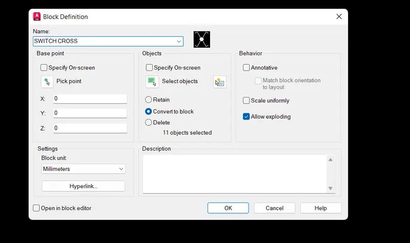
9.Draw the symbol using line and circle command, Create the cirle of 0.2 radius and draw a line at 60 and 120 degree and draw another small lines perpendicular to the angled lines and use Mirror command to draw bottom lines, offset the circle in inward direction by 0.05 and Hatch inside the circle

Select the object and type Block and give name as SWITCH CROSS and can be used any where in the drawing by using Insert command
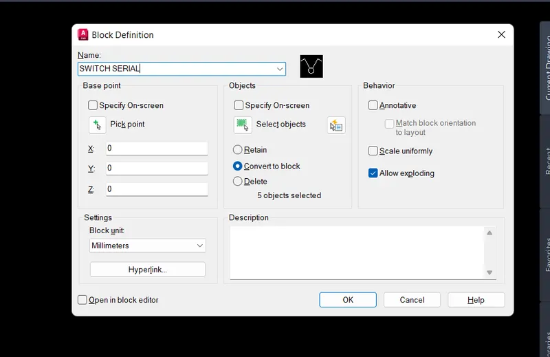
10.Draw the symbol using line and circle command, Create the cirle of 0.2 radius and draw a line at 60 and 120 degree and draw another small lines perpendicular to the angled lines

Select the object and type Block and give name as SWITCH SERIAL and can be used any where in the drawing by using Insert command
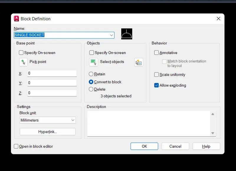
11. Draw the semicircle of radius 0.3, and a line of 0.2 from top point
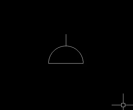
Select the object and type Block and give name as SINGLE SOCKET and can be used any where in the drawing by using Insert command
12. Draw the semicircle of radius 0.3, and a line of 0.2 from top point and a 0.1 horizontal line
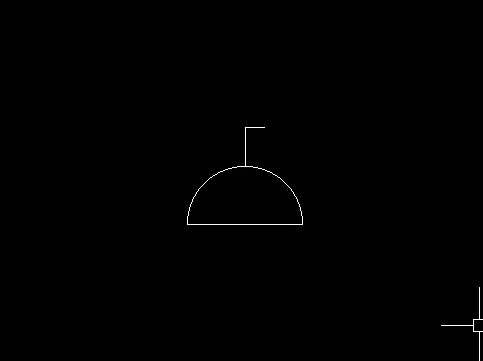
Select the object and type Block and give name as SINGLE SOCKET FOR LAMP and can be used any where in the drawing by using Insert command
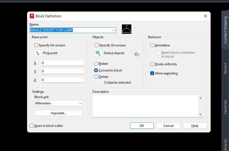
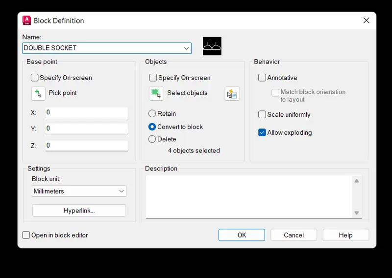
13. Draw same as single socket for lamp and copy it and place beside
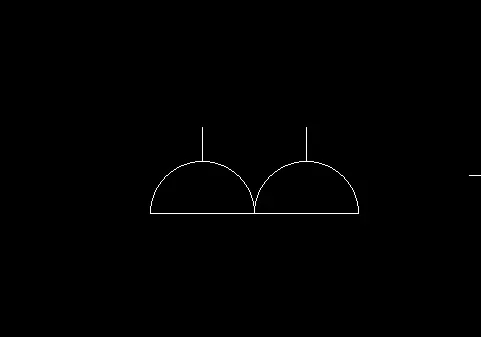
Select the object and type Block and give name as DOUBLE SOCKET and can be used any where in the drawing by using Insert command
14. Draw single socket and by using rectangle command draw rectangle and copy single socket in it
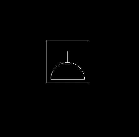
Select the object and type Block and give name as FLOOR SOCKET SINGLE and can be used any where in the drawing by using Insert command
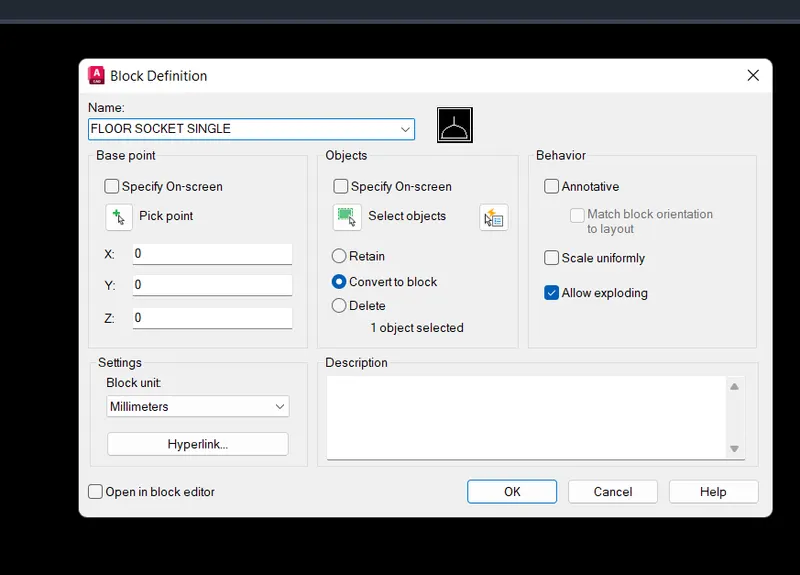
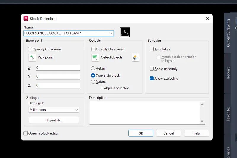
15. Draw single socket for lamp and by using rectangle command draw rectangle and copy the symbol in it
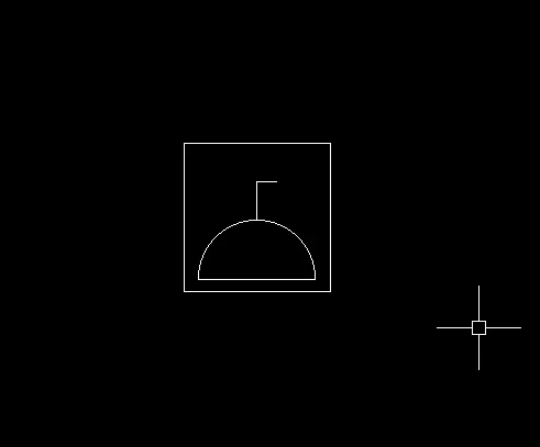
Select the object and type Block and give name as FLOOR SOCKET SINGLE FOR LAMP and can be used any where in the drawing by using Insert command
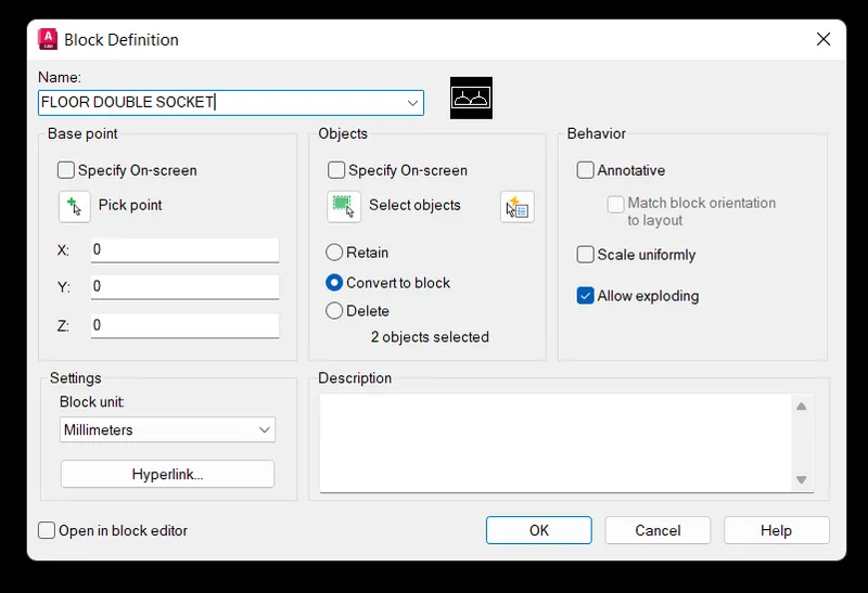
16. Type insert and select the double socket block and darg and using rectangle command draw rectangle and copy the symbol in it
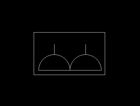
Select the object and type Block and give name as FLOOR SOCKET DOUBLE and can be used any where in the drawing by using Insert command
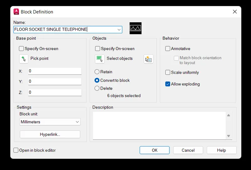
17. Insert single socket and draw triangle of base 0.6 and height 0.5 beside the single socket and copy them into rectangle

Select the object and type Block and give name as FLOOR SOCKET SINGLE TELEPHONE and can be used any where in the drawing by using Insert command
18. Insert double socket and draw triangle of base 0.6 and height 0.5 beside the single socket and copy them into rectangle
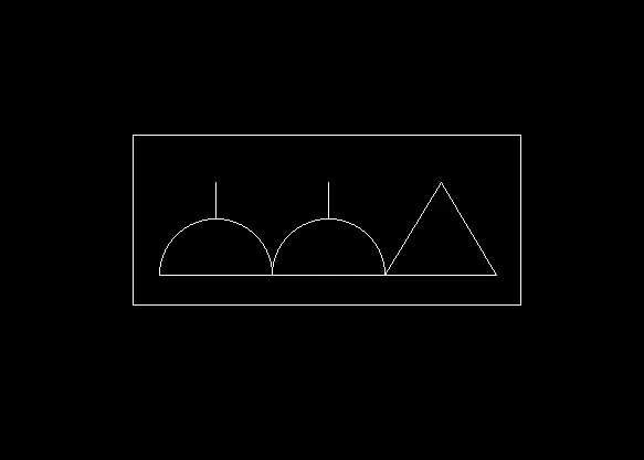
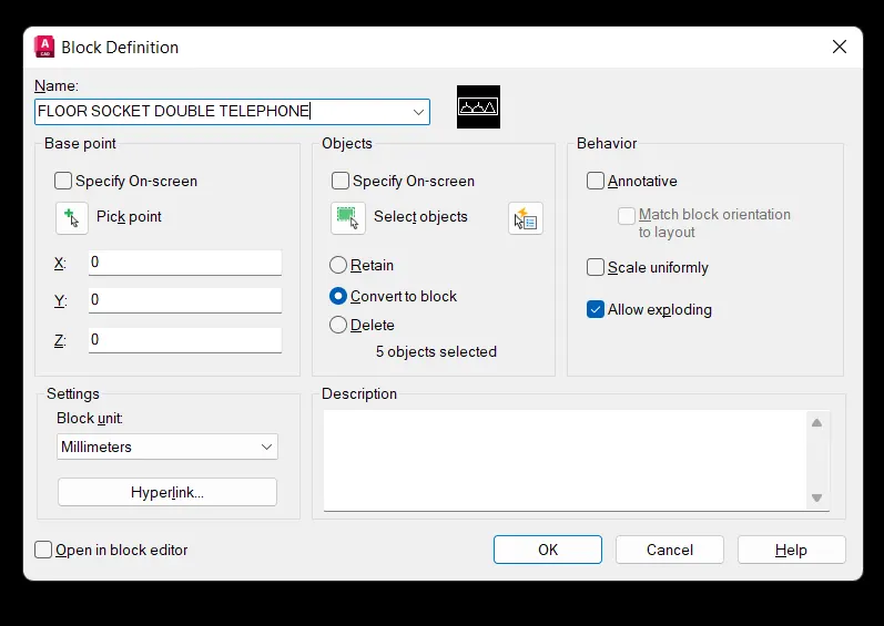
Select the object and type Block and give name as FLOOR SOCKET DOUBLE TELEPHONE and can be used any where in the drawing by using Insert command
19. Draw triangle of base 0.6 and height 0.5 using line command
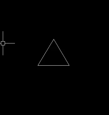
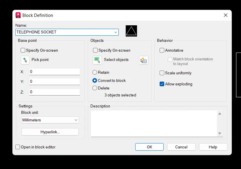
Select the object and type Block and give name as TELEPHONE SOCKET and can be used any where in the drawing by using Insert command
20.Draw triangle of base 0.6 and height 0.5 using line command and using Text write "i" inside the triangle taking font size as 0.3

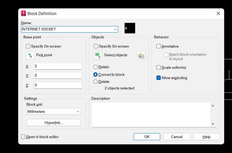
Select the object and type Block and give name as INTERNET SOCKET and can be used any where in the drawing by using Insert command
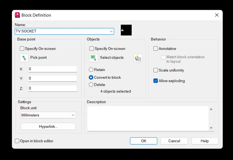
21. Draw triangle of base 0.6 and height 0.5 using line command and using Text write "TV" inside the triangle taking font size as 0.2

Select the object and type Block and give name as TV SOCKET and can be used any where in the drawing by using Insert command
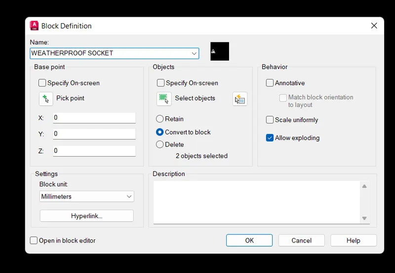
22. Draw triangle of base 0.6 and height 0.5 using line command and using Text write "W" inside the triangle taking font size as 0.2

Select the object and type Block and give name as WEATHERPROOF SOCKET and can be used any where in the drawing by using Insert command
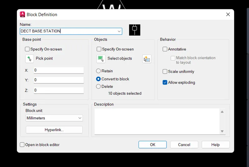
23. Draw the rectangle of 0.4X0.3 and remove the bottom horizontal line and draw arc, another lines are drawn by line and comand and increase the thickness of line for top lines
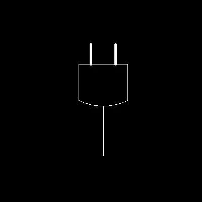
Select the object and type Block and give name as DECT BASE STATION and can be used any where in the drawing by using Insert command
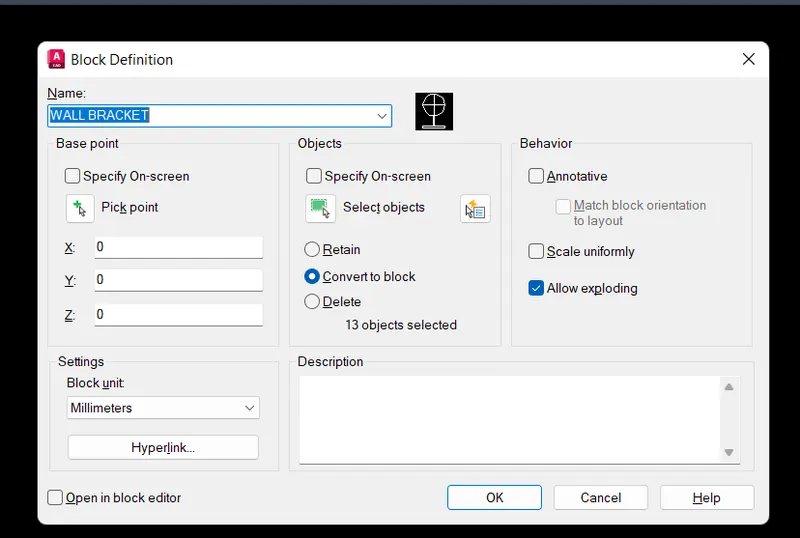
24.Draw the circle of radius 0.3 and using Line command draw the requried lines
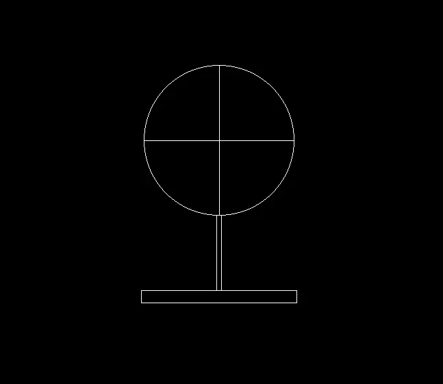
Select the object and type Block and give name as WALL BRACKET and can be used any where in the drawing by using Insert command
25.Using rectangle command and line command draw the symbol, And use scale as per required
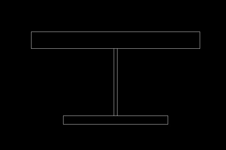
Select the object and type Block and give name as PICTURE LAMP and can be used any where in the drawing by using Insert command
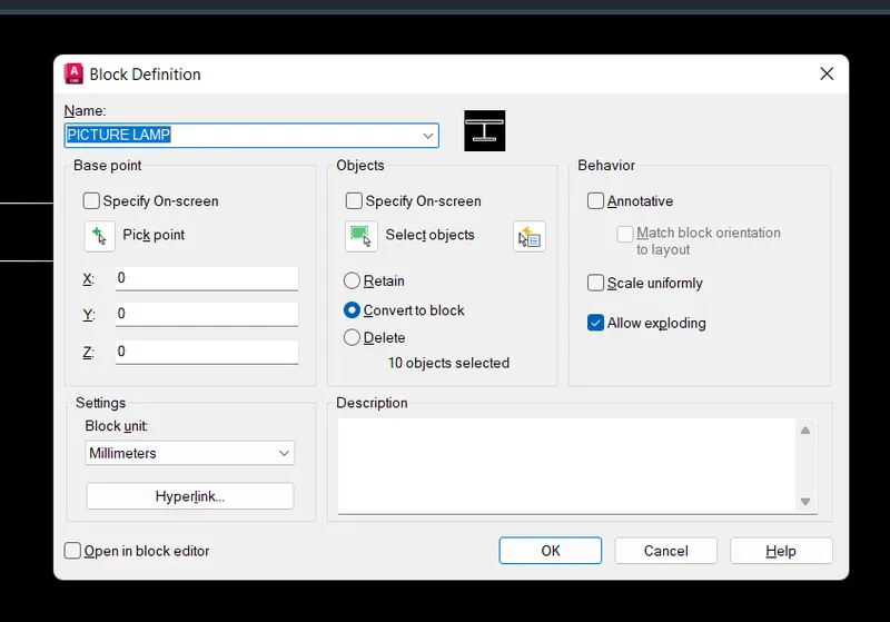
26. Go to tables and give No.of columns equal to 6 and No.of rows equal to 8 and 1st row is title and 2nd row is header remaining 8 rows are data type
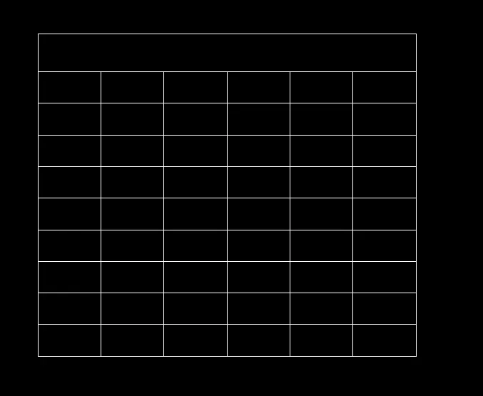
Adjust the size of the cells in the table as required by selecting and then draging
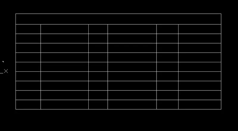
27. Used text style is Yu Gothic and size of for title is 40 and remaining text is 30
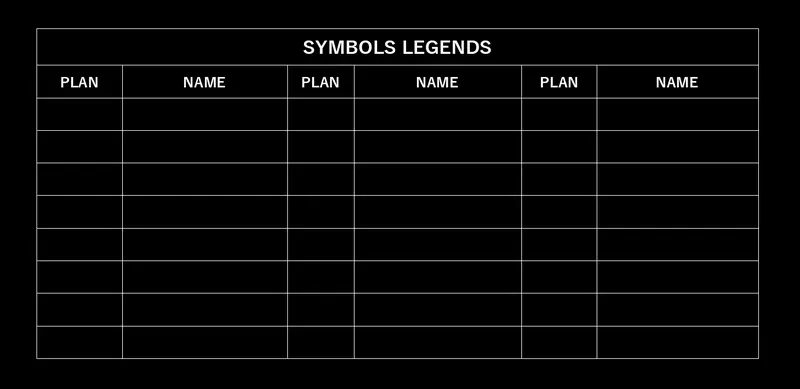
28. Type Insert and select the required block and place it, Using the scale command adjust th size of the symbol
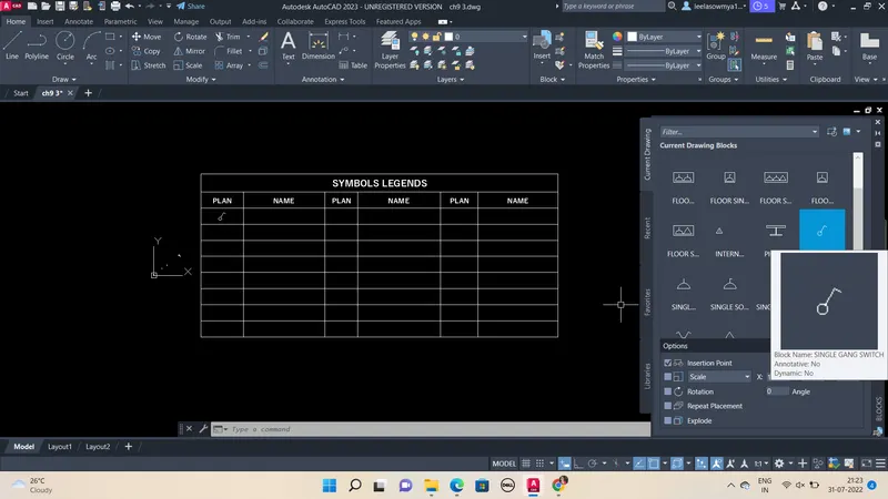
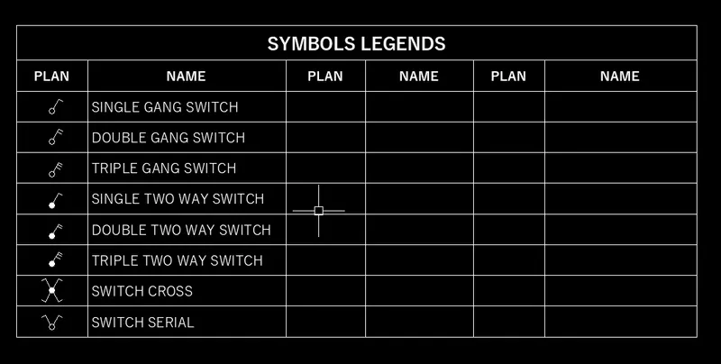
29. To insert the last two symbols, select the cells and use merge by rows, then place the symbols and divide by Line and write the Text using text command
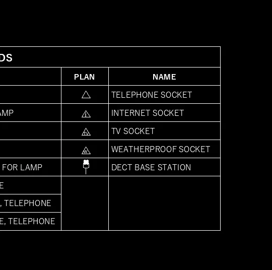
30. The final symbols legends table
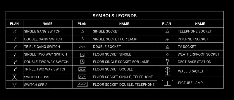
4. Aim: To create the door type for residential building as a block and to save the name of the blocks as type using Autocad software
Steps:
- Open new file in Autocad 2023, Type UNITS, use Engineering and take inches
- Then LIMITS, Limits of lower left corner give (0,0) and limits of upper right corner (100',100')
Door 1:
1. Use line command and draw using points (0,0) (@2'10",0) (@0,6'11") (@-2'10",0) (@0,-6'11")
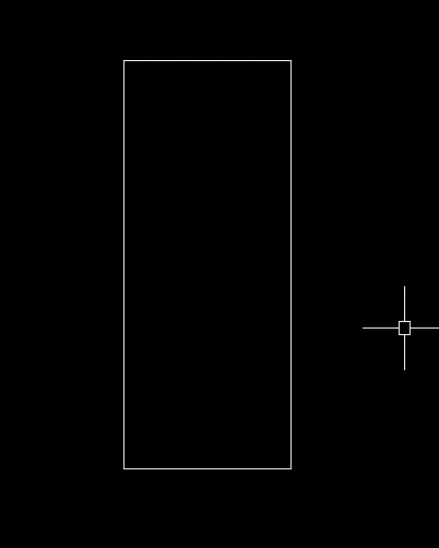
2. Offset the both vertical lines and top horizontal line in inward direction by 1.6" and then 1.2", and Trim all the extra lines
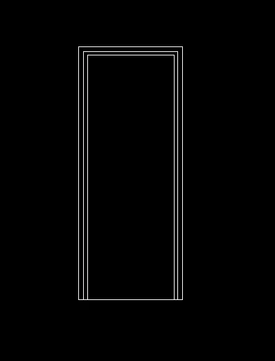
3. Using Line, circle and arc command draw the door handle, handle height is taken as 8.6" and width is 2" and radius of circle used is 0.6"

4. Place the hangle at a distance of 3'1" from the top inner horizontal line
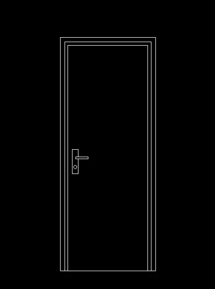
5. Measure dimension using Dimlinear and write the required text using Text command and used style Yu Gothic and size 8"
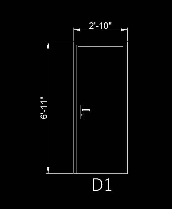
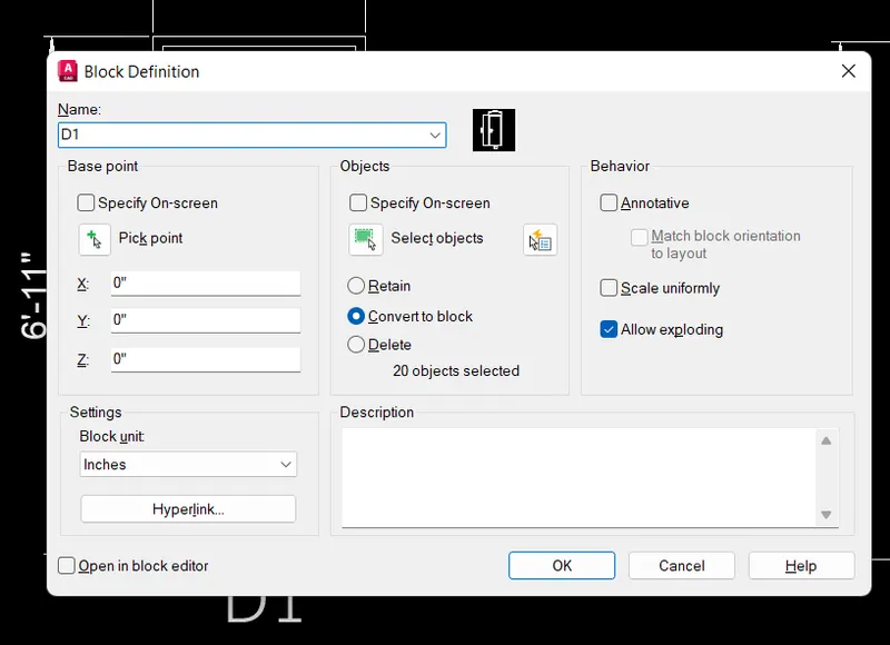
6. Select the door D1 and type Block and name it as D1
Door 2:
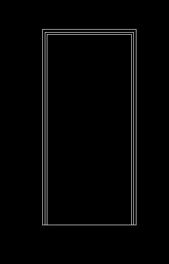
1.Use line command and draw using points (0,0) (@3'4",0) (@0,6'11") (@-3'4",0) (@0,-6'11")
Offset the both vertical lines and top horizontal line in inward direction by 1.2" and then 0.8", and Trim all the extra lines
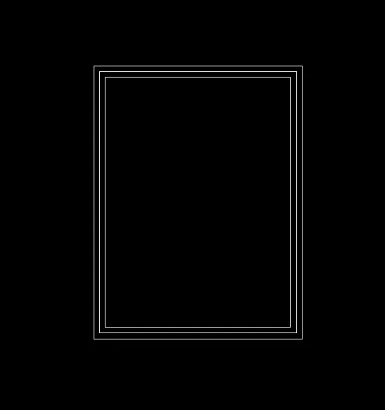
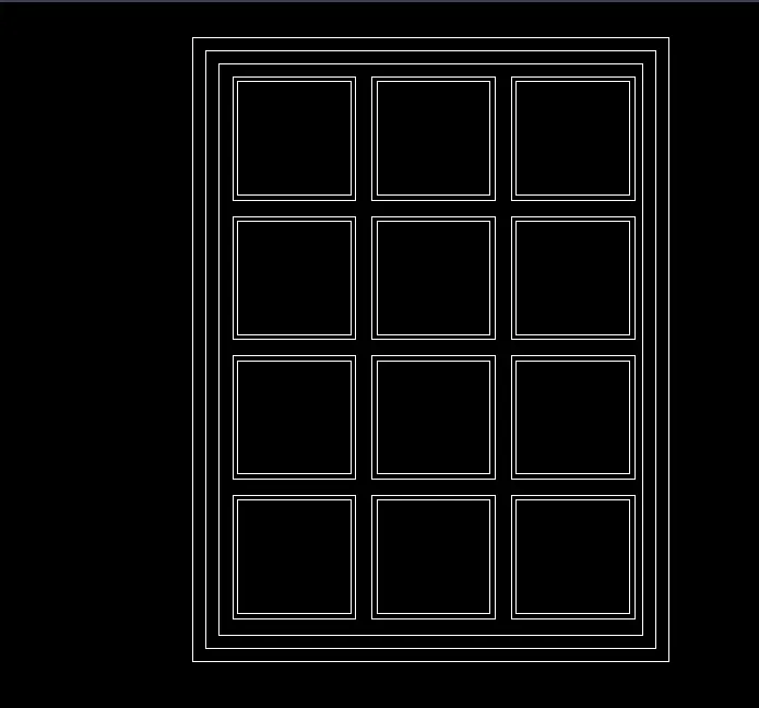
2. Using rectangle, create rectangle of size 2'5"X3'2" and offset the rectangle in inward direction by 0.8" and again 0.8"
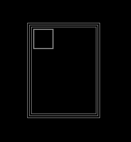
3. Place the square of size 7.5""X7.5"", such that top left corner of sqaure is at a distance of 0.8" from both inner top horizintal line and left vertical line
And Offset the square inward direction by 0.3"
4. Use array and select sqaures and No.of columns is 3 and distance between id 8.5" and No/of rows are 4 and distance is -8.5"
5. Draw the using rectangle 2'5"X2'5", and then offset towards inward by a distances of 0.8", 0.7", 0.9", 1.9" and then 0.9"

6. Place the drawn rectangle in the door, such that at a distance of 3.6" from the vertical line and 3.5" from top horizontal line and place it by using drawing reference lines and delete the lines later
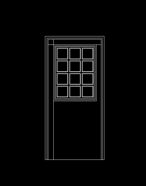
7. The squares are placed in door, they are a distance of 3.6" from the vertical line and 5.3" from bottom horizontal line
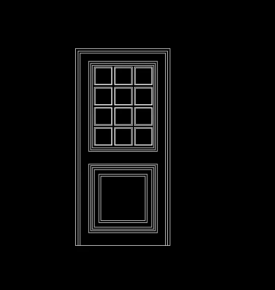
8. Draw the circle of radius 1.7" and then measure dimension using Dimlinear and write the required text using Text command and used style Yu Gothic and size 8"
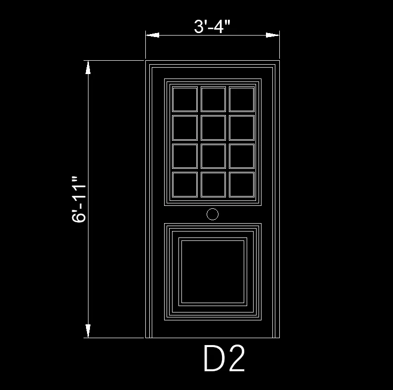
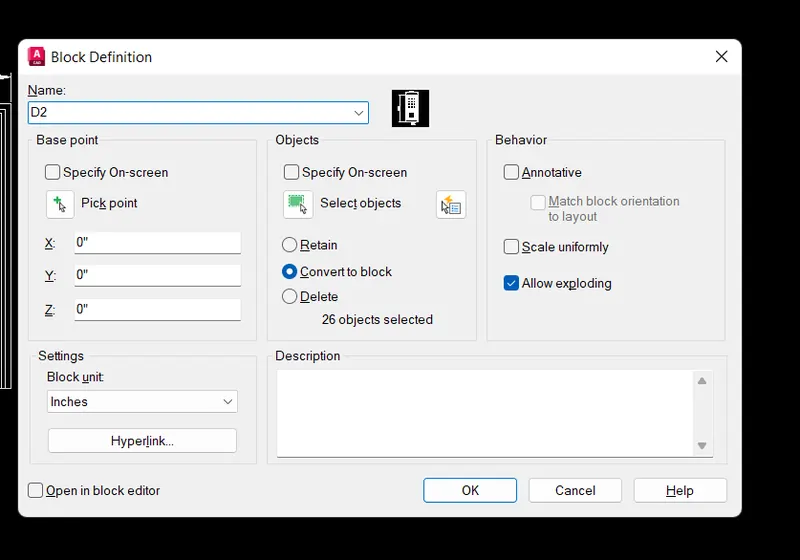
9. Select the door D2 and type Block and name it as D2
Door 3:
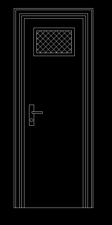
1. Use line command and draw using points (0,0) (@2'9",0) (@0,6'11") (@-2'9",0) (@0,-6'11")
Offset the both vertical lines and top horizontal line in inward direction by a distances of 0.7", 1.6", 0.8" ,1.1" and Trim all the extra lines
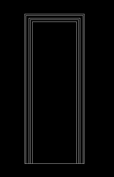
2. Draw a rectangle of 1'5"X11.6" and offset it by 1.2" inward and then hatch the inner rectangle
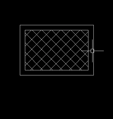
3. Place the rectangle in the door at a distance of 4" from inner vertical and horizontl lines by drawing reference lines and then delete lines
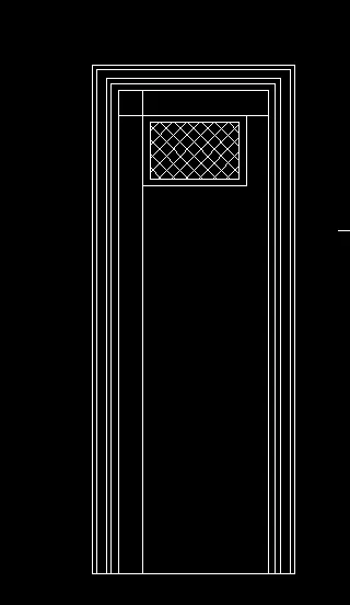
4. Place the door handle at a distance of 3' from top inner horizontal line and use same handle in door 1
5. Measure dimension using Dimlinear and write the required text using Text command and used style Yu Gothic and size 8"
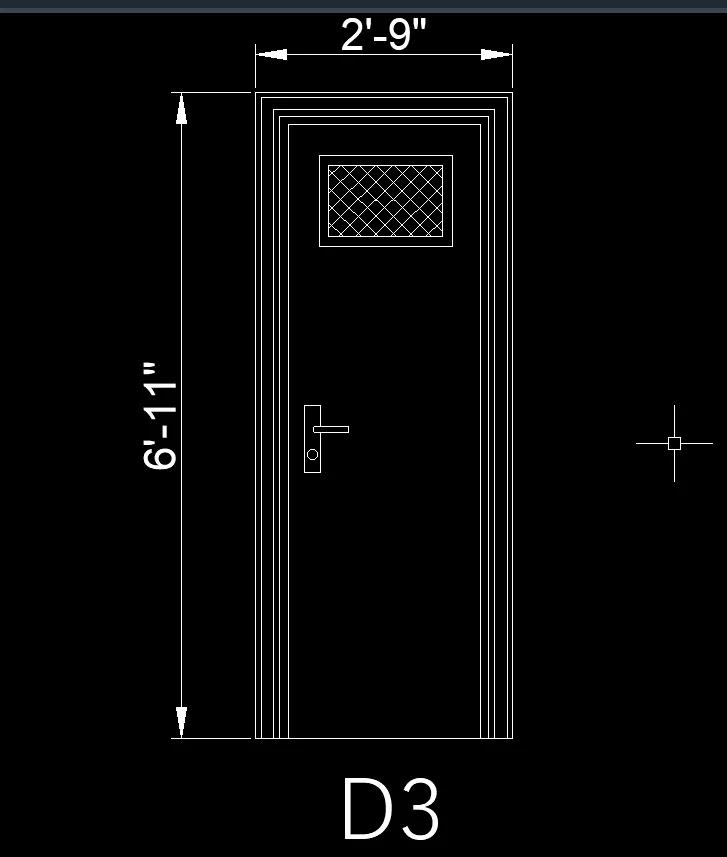
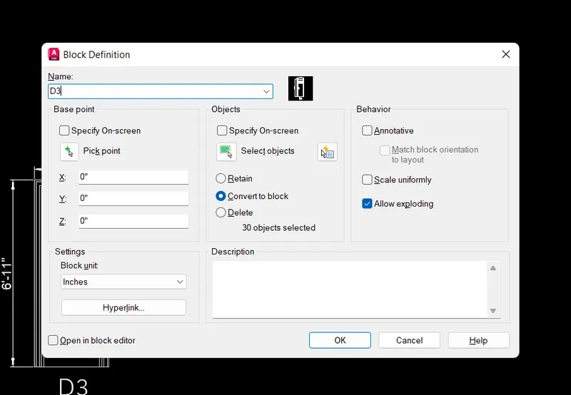
6.Select the door D3 and type Block and name it as D3
Door 4:
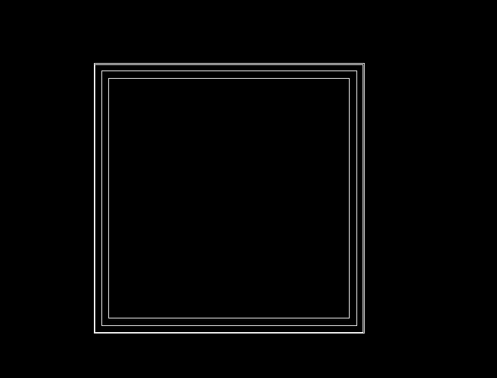
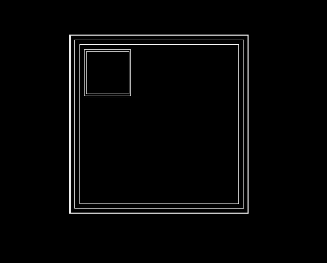
1. Draw the using rectangle 2'5"X2'5", and then offset towards inward by a distances of 0.8", 0.7"
2. Place the square of size 7.5""X7.5"", such that top left corner of sqaure is at a distance of 0.8" from both inner top horizintal line and left vertical line
And Offset the square inward direction by 0.3"
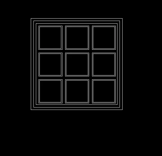
3. Use array and select sqaures and No.of columns is 3 and distance between id 8.5" and No/of rows are 3 and distance is -8.5"
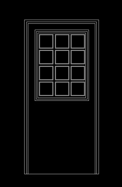
4. Select and copy the door D2 and remove the bottom sqaures and dimensions.
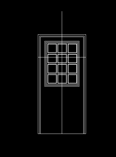
5. Draw the vertical line at mid of horizontal lines anf Offset the Bottom horizontal line by 5'4" in upward direction
6. By using Arc- Start End Angle, draw the arc from intersection of both lines,
Similarly draw the arcs at all intersections
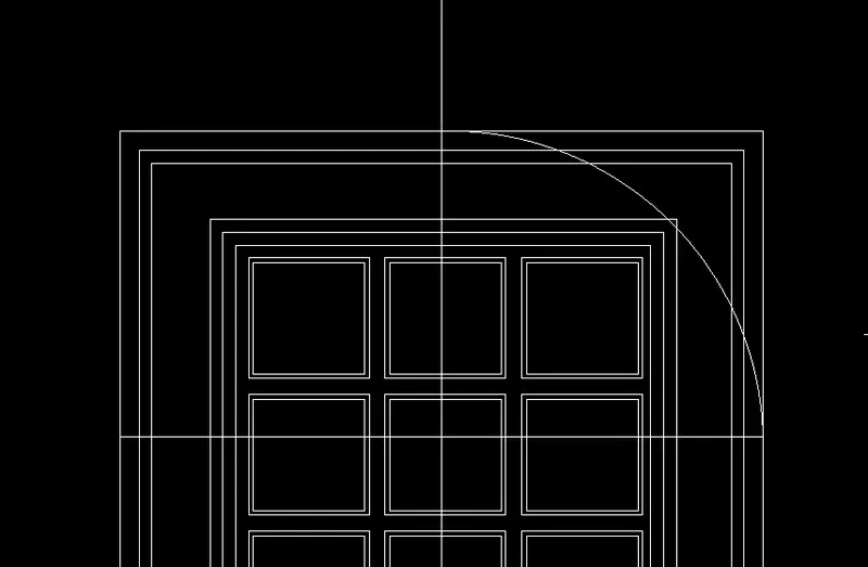
7. Draw all the intersections
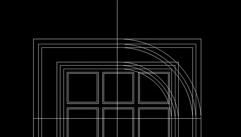
8. Select the Arcs and use Mirror command and mirror it
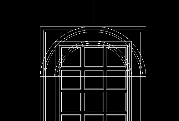
9. Trim all the unnecessary lines carefully
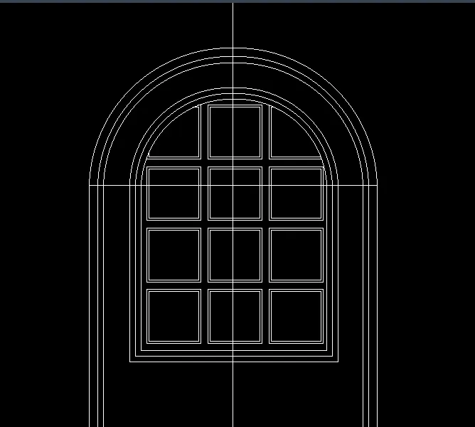
10. Offset the inner arc by 0.7" and then 0.3"
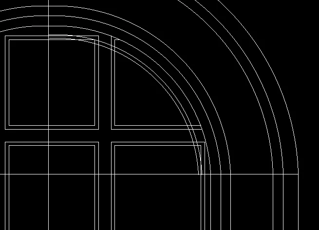
Then Trim all the unnecessary lines
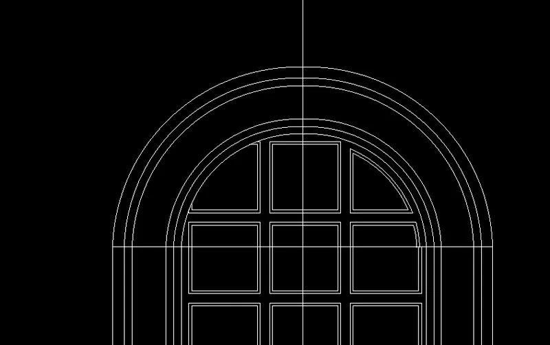
Do same on the otherside and the delete the reference lines
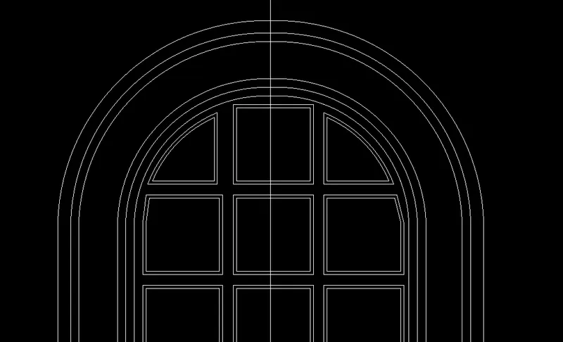
11.The squares are placed in door, they are a distance of 3.6" from the vertical line and 5.3" from bottom horizontal line and circle radius 1.7" is placed
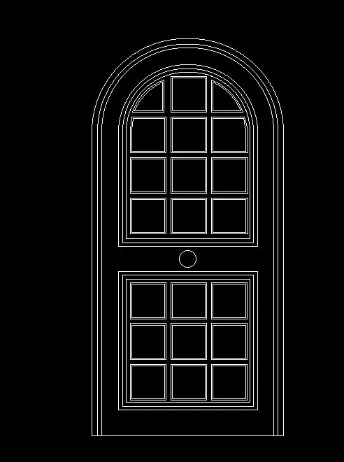
12. write the required text using Text command and used style Yu Gothic and size 8"
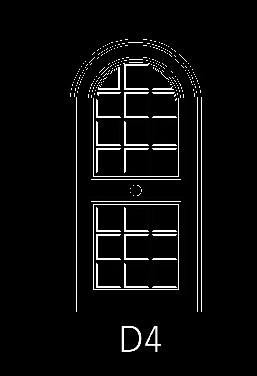
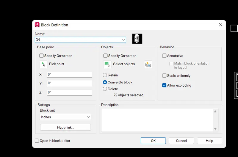
13.Select the door D4 and type Block and name it as D4
Door 5:
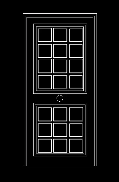
1. Select and copy the door D2 and remove the bottom sqaures and dimensions, as below
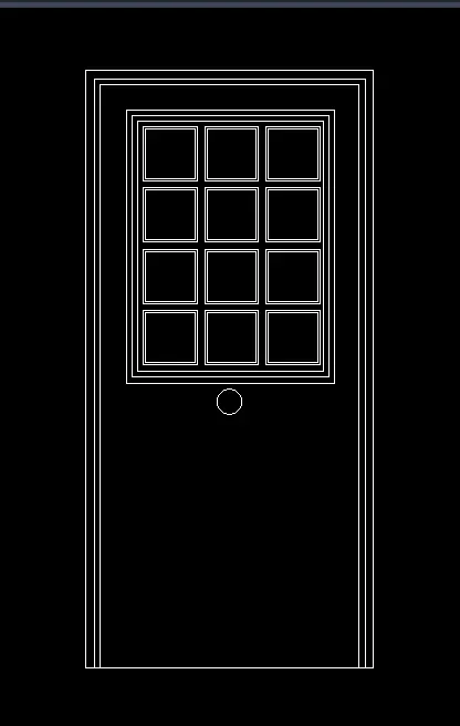
2. Copy it from Door D4
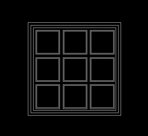
3.The squares are placed in door, they are a distance of 3.6" from the vertical line and 5.3" from bottom horizontal line
4. write the required text using Text command and used style Yu Gothic and size 8"
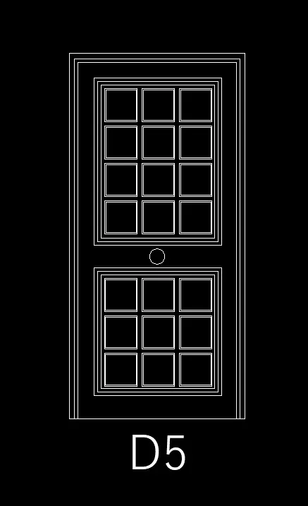
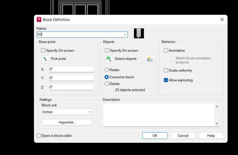
5. Select the door D5 and type Block and name it as D5
Door 6:
1. Select and copy the door D4 and remove the bottom sqaures and text, as below
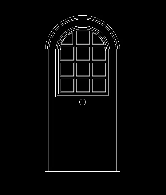
2. Select and copy the squares from the Door 2

3. The squares are placed in door, they are a distance of 3.6" from the vertical line and 5.3" from bottom horizontal line and write the required text using Text command and used style Yu Gothic and size 8"
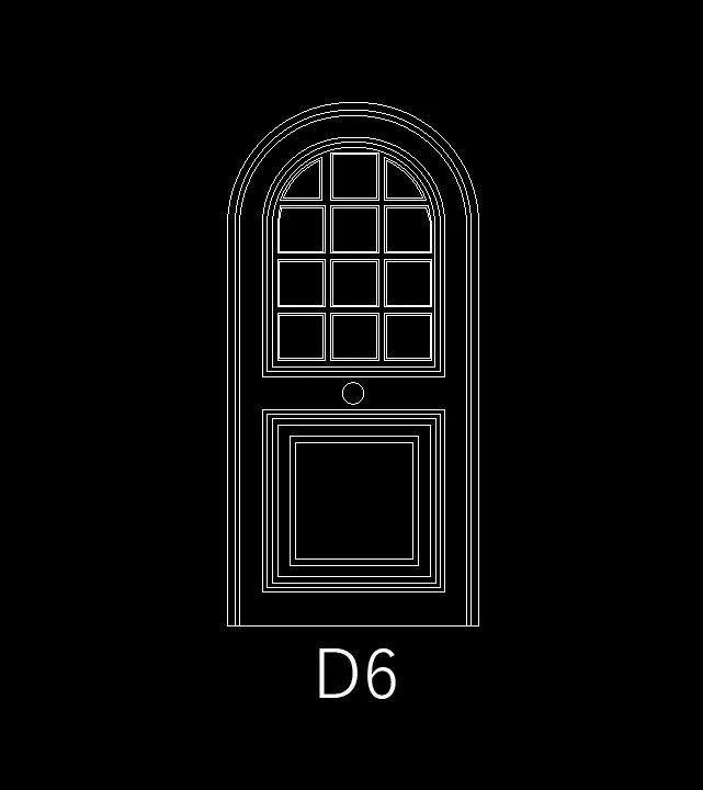
4.Select the door D6 and type Block and name it as D6
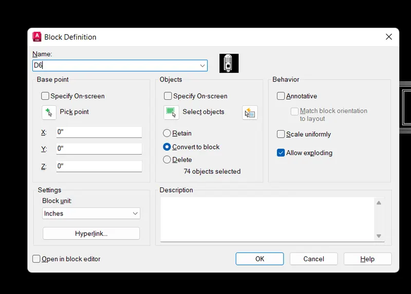
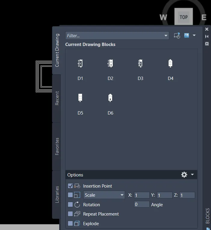
5. Type Insert, we can use the created Blocks
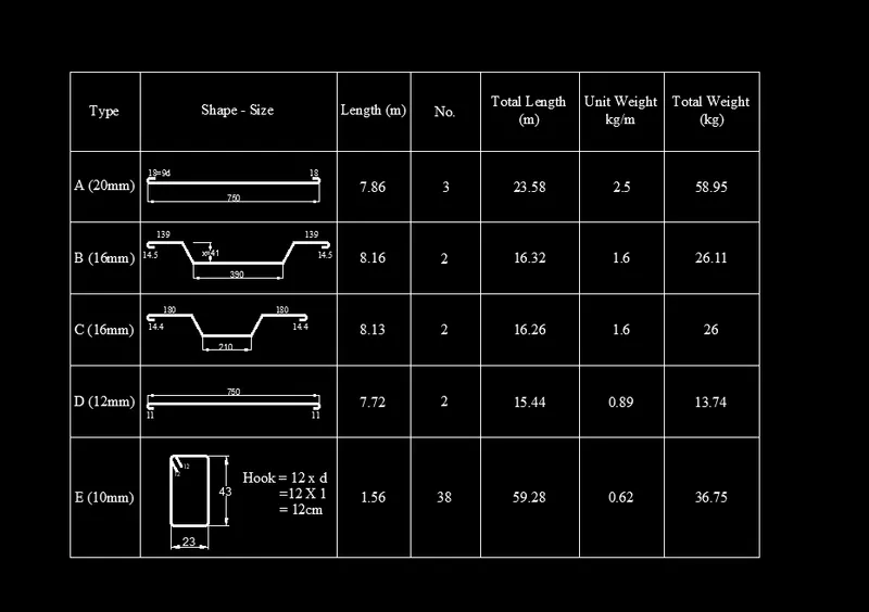
5. Aim: To create given bar bending schedule using Autocad software and each shape is created as block and to be inserted in the table
Steps:
1.Open new file in Autocad 2023, Type UNITS, use decimal and take millimeters
2. Then LIMITS, Limits of lower left corner give (0,0) and limits of upper right corner (10000,10000)
3. Draw a line using Line command of length 730 and draw 18 line at the Top of corners and a distance of 20, then use Fillet and fillet the Lines

Increase the Line thickness, and measure the Dimension and write the required text using Times New Roman Greek style and size 25
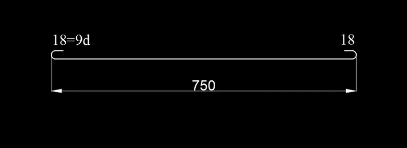
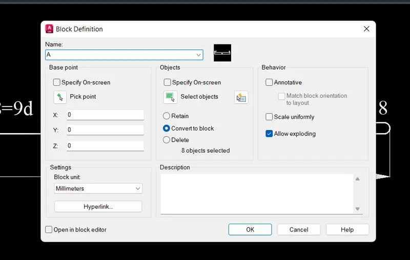
Select the object and type block, then name the block as A
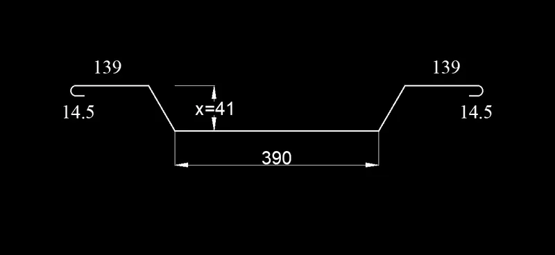
4. Draw a line of 390 and draw another line an angle and the using direct distance method draw 139 line 14.5 and another line at the corners and a distance of 20, then use Fillet
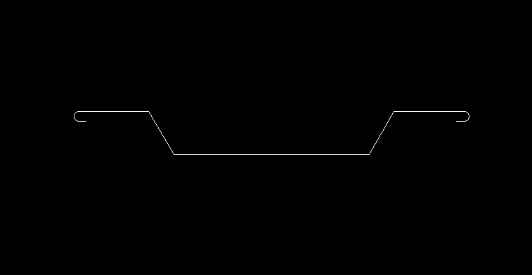
Increase the Line thickness, and measure the Dimension and write the required text using Times New Roman Greek style and size 25
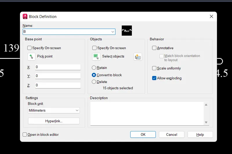
Select the object and type block, then name the block as B
5. Draw a line of 210 and draw another line an angle and the using direct distance method draw 180 line 14.4 and another line at the corners and a distance of 20, then use Fillet
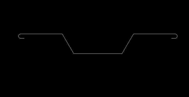
Increase the Line thickness, and measure the Dimension and write the required text using Times New Roman Greek style and size 25
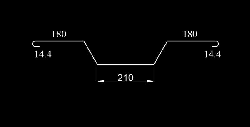
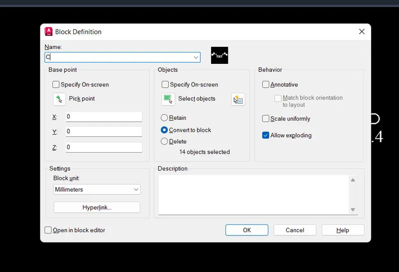
Select the object and type block, then name the block as C
6. Draw a line using Line command of length 730 and draw 11 line at the corners and a distance of 20, then use Fillet and fillet the Lines
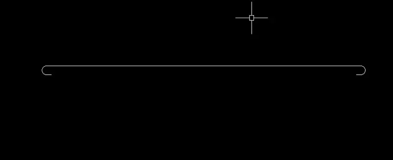
Increase the Line thickness, and measure the Dimension and write the required text using Times New Roman Greek style and size 25
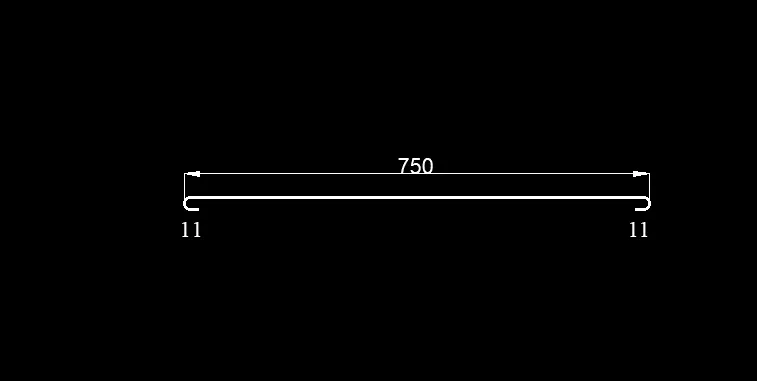
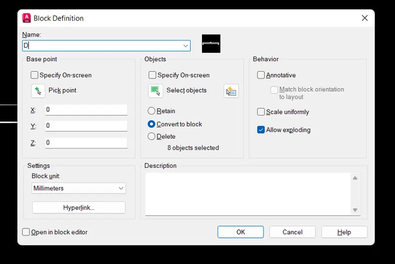
Select the object and type block, then name the block as D
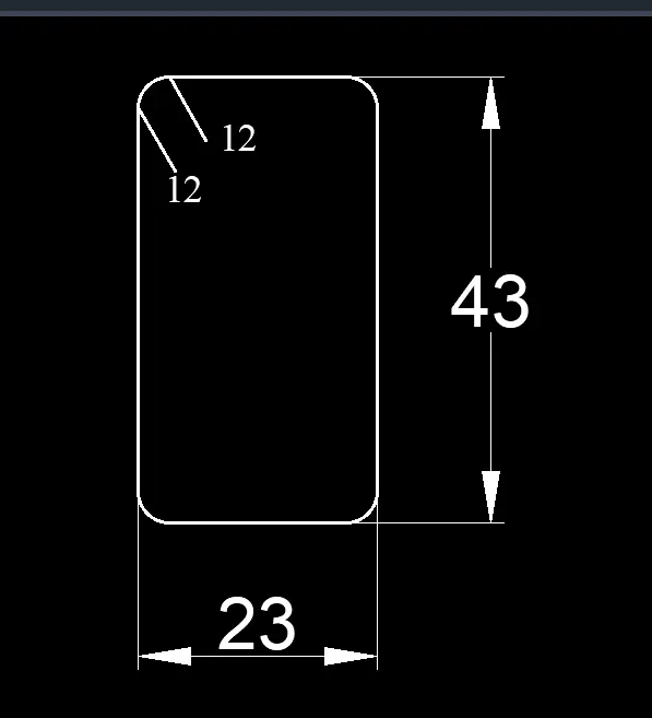
7. Draw a rectangle of 23X43, and fillet the corners with fillet radius 3 and draw the required lines using Line

Increase the Line thickness, and measure the Dimension and write the required text using Times New Roman Greek style and size 25
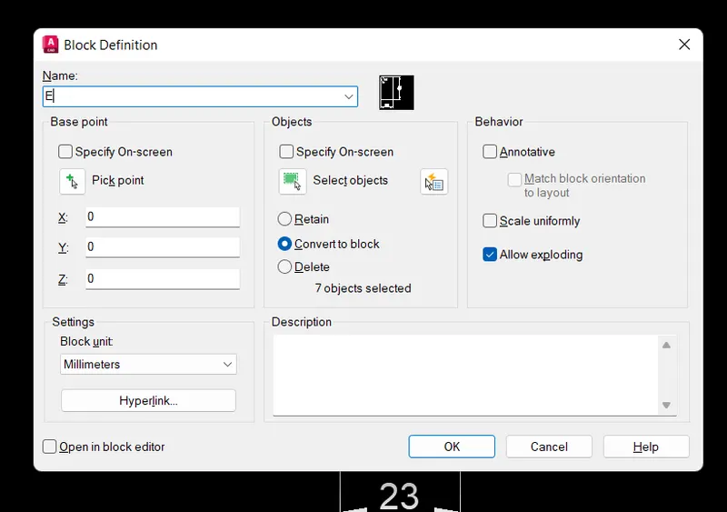
Select the object and type block, then name the block as D
8. Create the table with No.of columns equal to 7 and total rows are 6, First row is taken as Header and remaining as Data type
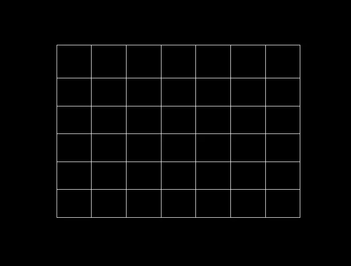
9.Adjust the table cell size as per required, just by draging the points
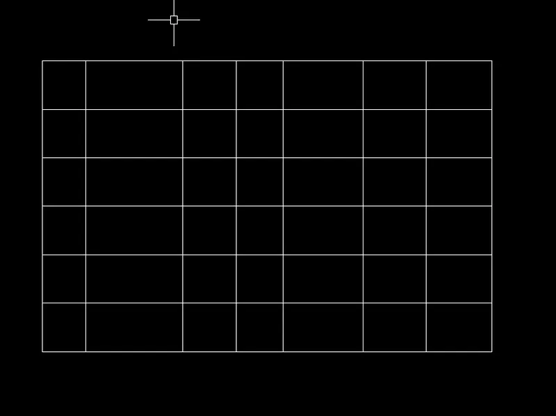
Write the Text of style Times New Roman Greek, And type INSERT and place the blocks at required places
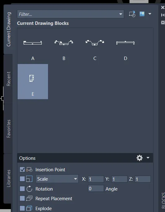
select the blocks and drag, then scale the object according to the cell size
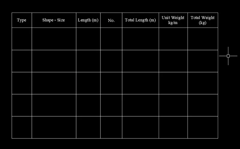
The final Bar bending schedule