Creating Bar Bending schedule, Different Door types, and Creation of standard drawing templates using AutoCad
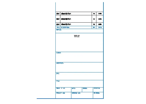
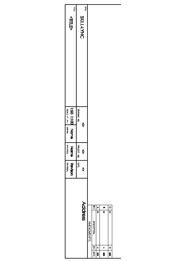
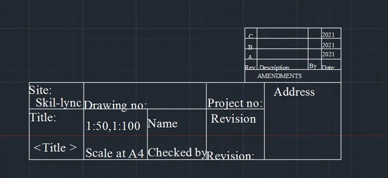
1. Create the templates as shown in Figures. Take the size of the title block as per industry standards or you can assume it as per the size of the paper. Use text and attributes wherever required. After creating the title block you need to save it as a block with names: Custom1_titleblock and Custom2_titleblock, respectively.
AIM:
To Create the title block you need to save it as a block with names: Custom1_titleblock and Custom2_titleblock, respectively.
Command are used:
- Units
- Limmax
- Limits
- Line
- Offset
- Text
- Block
- Layer
- Dimension
- Dimension style
Procedure:
- First we set an unit as per the engineering and dimenion of inch have choosed
- Next we et limmax and limit spec @0,0 and 20,20
- Then z enter and a enter
-
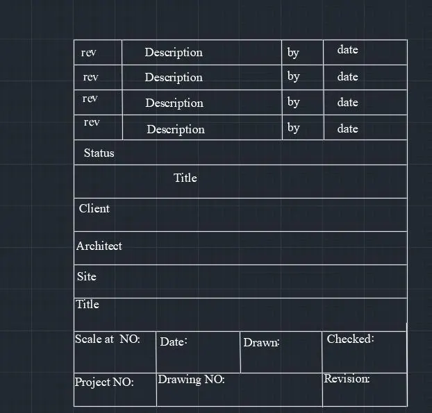
- Take a table at required rows and columns as respetcively
- Choose single line text and write over the table
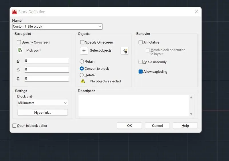
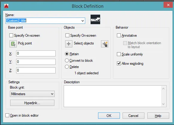
- Choose the object to creating to the block and we gives the name as the Custom1_title
- Same Take a table at required rows and columns as respetcively
- Choose single line text and write over the table
- Choose the object to creating to the block and we gives the name as the Custom2_title
Result:
We draw the text as per shown figure.
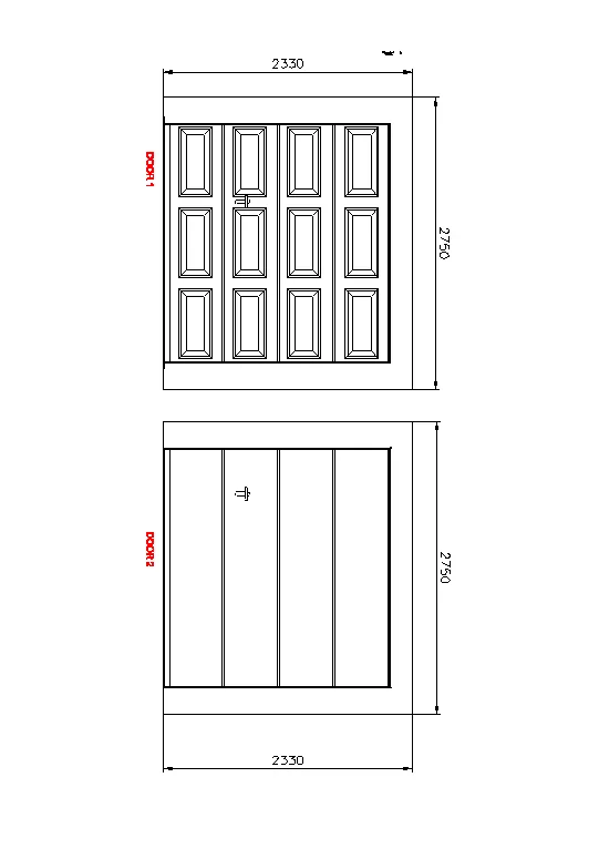
2. Create the doors type for warehouse as shown in the Figure. You need to create each door type as per standard size or given dimensions. Create the blocks of this door type after creating them.
AIM:
To create each door type as per standard size or given dimensions.
Command are used:
- Units
- Limmax
- Limits
- Line
- Offset
- Text
- Block
- Layer
- Dimension
- Dimension style
- Circle
- Arc
PROCEDURE:
- First we set an unit as per the engineering and dimenion of mm have choosed
- Next we et limmax and limit spec @0,0 and 20,20
- Then z enter and a enter
- Outer layout 2330mm and 2775mm repectively
- Get an offset to the outer dimension
- To give the partion over the inner of the full dimenion we get at the 436mm.
- Create the box for the door type
- Copy the door style and placed the rows and column of 3 and 4
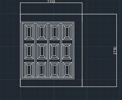
Give the handle of the door
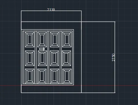
- Give the annotation of the door
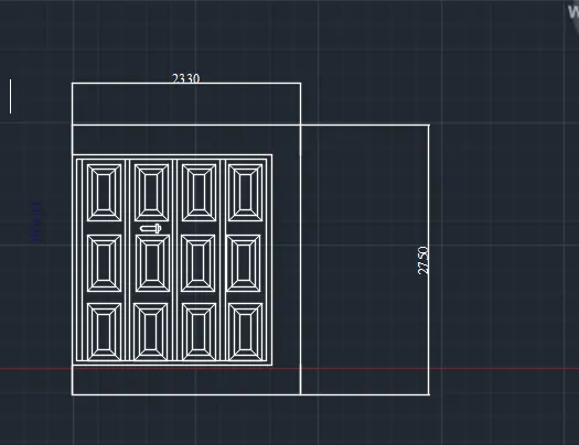
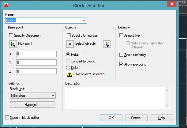
Take the block command as the name of the "Door" Select the specific point and the object and
Sve it
RESULT:
Fianlly we draw the door as per the dimension.
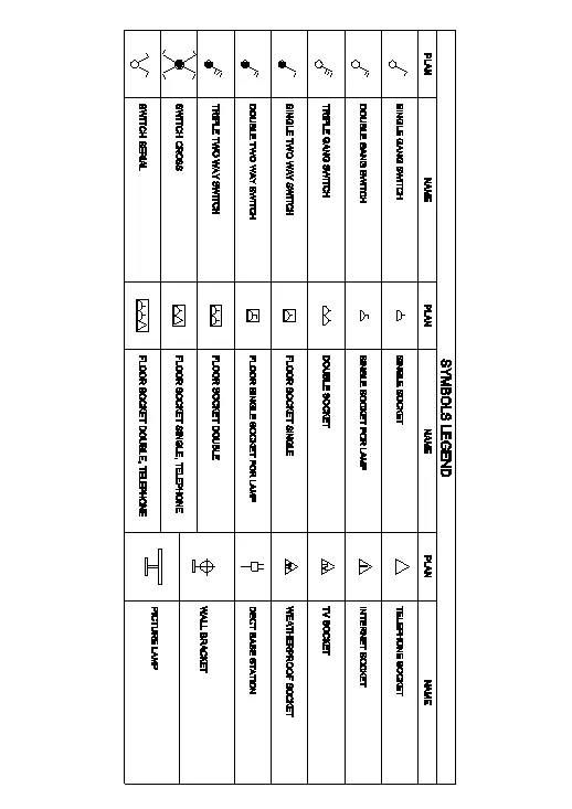
3. Create each symbol as a block with the name given in the legend. After creating the blocks arrange them in the legend as shown in the Figure.
AIM:
To Create each symbol as a block as named at the given figure.
COMMAND USED:
- Units
- Limmax
- Limits
- Line
- Offset
- Text
- Block
- Layer
- Dimension
- Dimension style
- Circle
- Arc
PROCEDURE:
- Use command type C to get the circle
- Next type L to get the lines
- Command > annotation> Multiline text
-
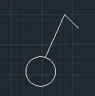
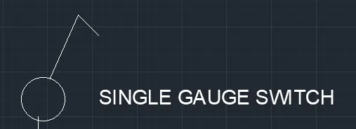
- Gives the block command named as single gange switch
-
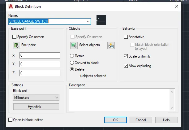
- same commands and procedure are followed for all the symbols
-
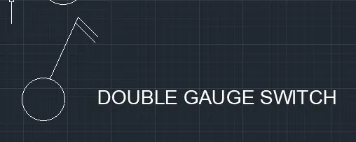
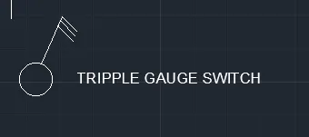
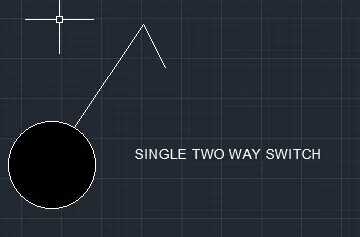
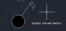
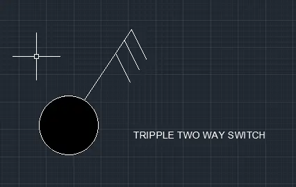
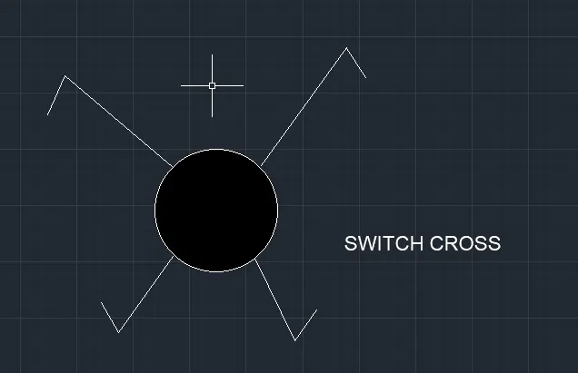
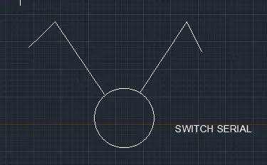
- In the command arc to draw the arc
- In the command prompt type Mtext
- In the > block>create block
-
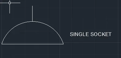
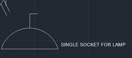
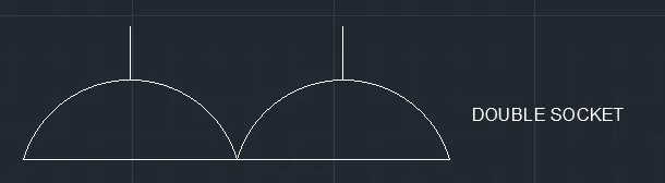
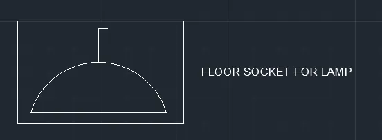
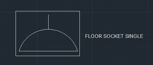
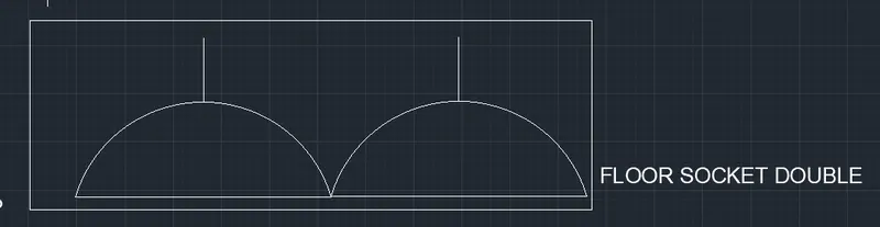
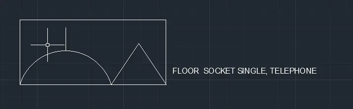
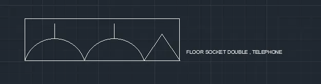
- In the command l to draw the lines
- In the commandtype Mtext
- In the ribbon bar > block>create block
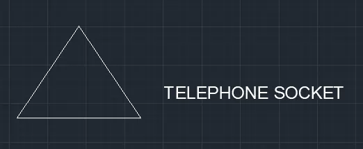
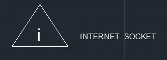
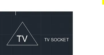
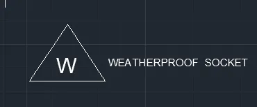
- In the command l to draw the lines
- In the command fillet to get the curves
- In the command type Mtext
- In the ribbon bar > block>create block
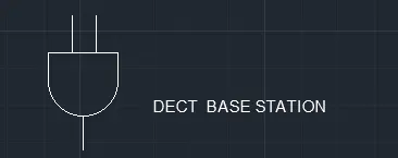
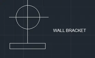
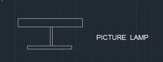
- In the coomant prompt type I to insert the blocks
FINAL RESULT :
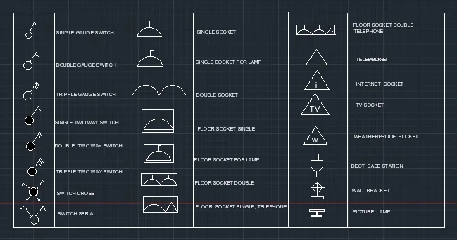
We get the electrical symbols.
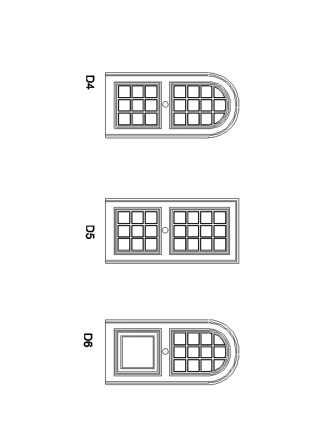
4. Create the door type for residential building as a block. Save the name of the blocks as type. Use given dimensions or assume dimensions as per industry standards.
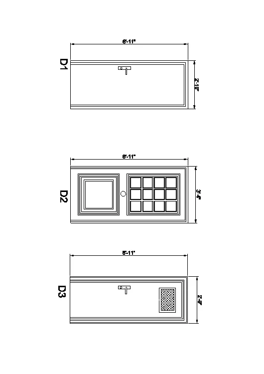
AIM:
To Create the door type for residential building as a block. Save the name of the blocks as type.
COMMAND USED:
- Units
- Limmax
- Limits
- Line
- Offset
- Text
- Block
- Layer
- Dimension
- Dimension style
- Circle
- Arc
PROCEDURE:
- First we set an unit as per the engineering and dimenion of inch have choosed
- Next we et limmax and limit spec @0,0 and 20,20
- Then z enter and a enter
- Outer layout 2'10" and 6'10 repectively
- Get an offset to the outer dimension
- To give the partion over the inner of the full dimenion
- To draw the handle
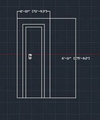
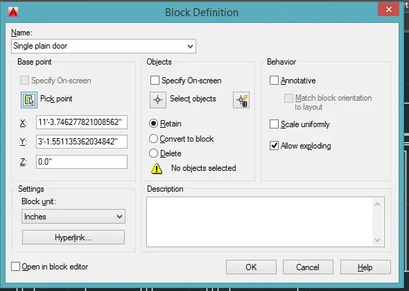
To create the block plain single door and give the dimension
- The 2nd drawing Outer layout 3'4" and 6'4" respectively
- Get an offset to the outer dimension
- To give the partion over the inner of the full dimension
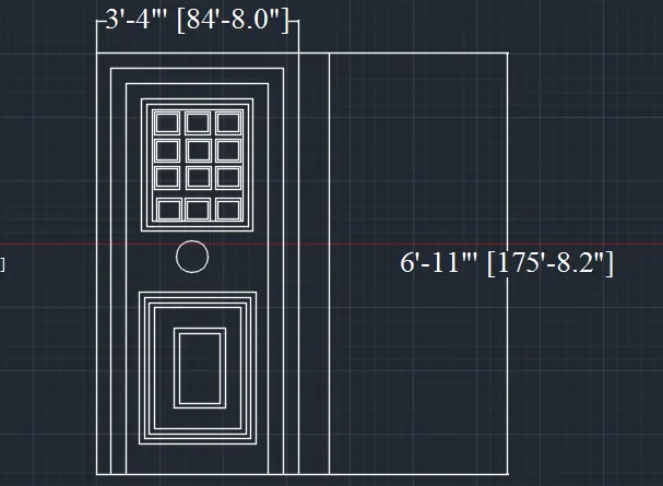
- Text command as the Door 2 and give the layer
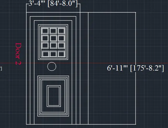
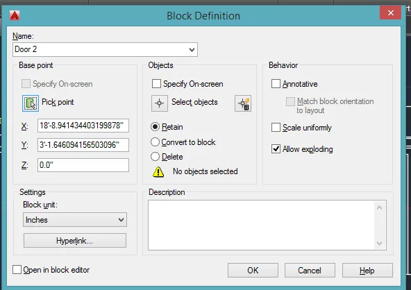
- Choose the Block command and named as the Door 2
- Choose the selective point and object
- The 3rd drawing Outer layout 2'9" and 6'11" respectively
- Get an offset to the outer dimension
- To give the partion over the inner of the full dimension
- Gives the rectangular a per the spec
- Command hatch to fill the rectangle
- Draw the handle bar as per the spec dimension
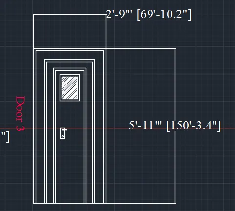
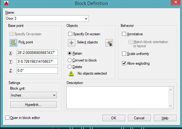
- Text command and choose the single line text Door 3 as the dimensions
- Noted as the block command gives the name of Door 3 select the point and objects
- The 4th drawing Outer layout
- Get an offset to the outer dimension
- To give the partion over the inner of the full dimension
- Gives the rectangular joint over the arc door style
- Draw the box and copy of the object and paste it
- The copied of the drawing are paste proper spacing
- Gives the dimension for the check of the outer dimension
- Draw the handle bar as per the spec dimension
- Take the text and gives the door 4
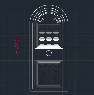
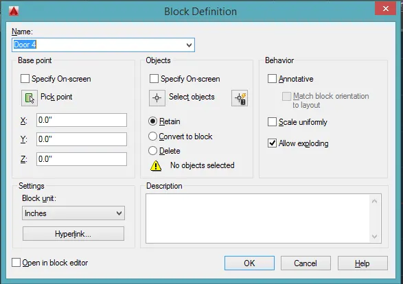
An action of the block named as door 4 select the point and object
- The 5th drawing Outer layout
- Get an offset to the outer dimension
- To give the partion over the inner of the full dimension
- Gives the rectangular joint over the arc door style
- Draw the box and copy of the object and paste it
- The copied of the drawing are paste proper spacing
- Gives the dimension for the check of the outer dimension
- Draw the handle bar as per the spec dimension
- Take the text and gives the door 5
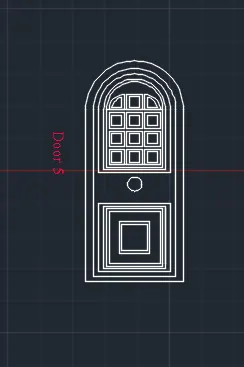
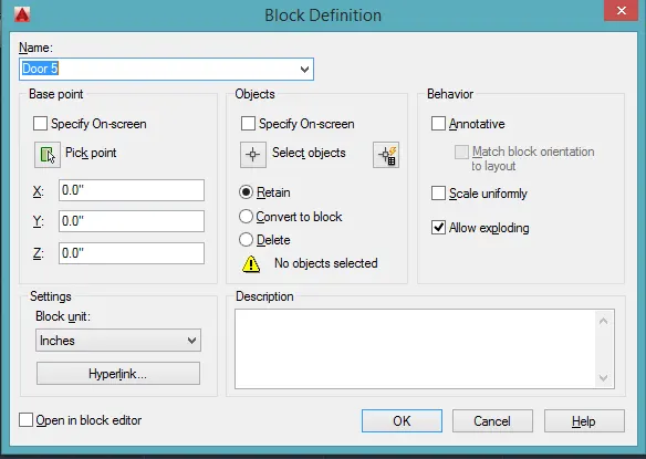
An action of the block named as door 5 select the point and object
- The 6th drawing Outer layout
- Get an offset to the outer dimension
- To give the partion over the inner of the full dimension
- Gives the rectangular joint over the arc door style
- Draw the box and copy of the object and paste it
- The copied of the drawing are paste proper spacing
- Gives the dimension for the check of the outer dimension
- Draw the handle bar as per the spec dimension
- Take the text and gives the door 6
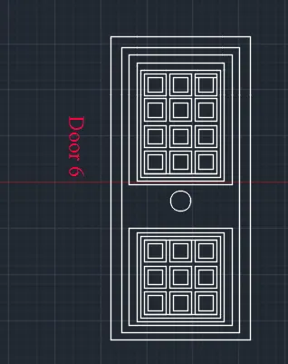
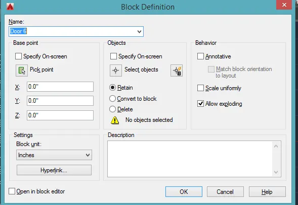
An action of the block named as door 6 select the point and object
RESULT:
Finally we draw the door as per industry standards
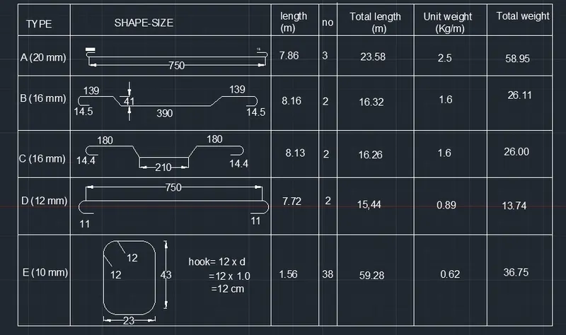
5. Create each shape as a block as shown in the Figure. Save the block and insert them on the table as shown in the Figure.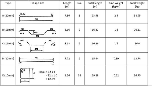
AIM:
To Create each shape as ablock and insert them on the table as given in the picture
COMMAND ARE USED:
- Line
- Offset
- Text
- Block
- Layer
- Dimension
- Dimension style
- Circle
- Arc
- Unit
- Limits
PROCEDURE:
- First we set an unit as per the engineering and dimenion of mm have choosed
- Next we et limmax and limit spec @0,0 and 20,20
- Then z enter and a enter
- The command l to draw the desired lines
- In the command pl to draw the desired arc,poly lines
- In the command mt to give annotation and text
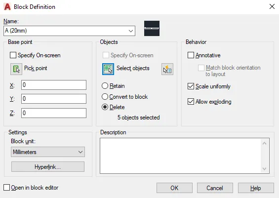
- In the command B to create the block
- In the command I to insert the created in the block
- In the command table to inset the table
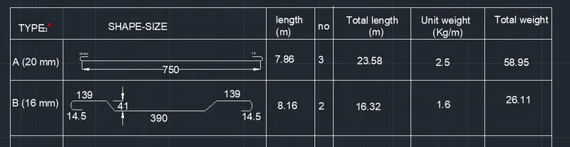
- Create the block as column schedule
Result:
Finally we draw the column schedule.