Creating Bar Bending schedule, Different Door types, and Creation of standard drawing templates using AutoCad
1. Create the templates as shown in Figures. Take the size of the title block as per industry standards or you can assume it as per the size of the paper. Use text and attributes wherever required. After creating the title block you need to save it as a block with names: Custom1_titleblock and Custom2_titleblock, respectively.
Aim: To Create the templates as shown in figure and to save it as blocks with names Custom 1 Titleblock and Custom 2 Titleblock and to use text and attributes wherever needed.
Introduction: The given drawing consists of a template which comprises of details of the project such as title,drawing no,date,revision,drawn by etc., This template is generally used in all professional projects prepared so as to provide the details of the project.
Steps:

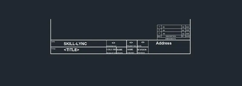
- The initial step is to create a table of required rows and column
- Then a text style is defined for the details to be filled in for the template
- Then using the mtext command text are included in the table.
- Then after creating the template, colour and lineweight is changed as per the requirement from the ribbon
- Then using block command the drawn template is created as a block and saved as Custom 1 titleblock and Custom 2 titleblock respectively
- The purpose of saving as a block is to use it in future diagrams
Results: The given template file has been created and usage of blocks and different text styles are done. The purpose of providing details about the drawing has been achieved by creating this template.
2. Create the doors type for warehouse as shown in the Figure. You need to create each door type as per standard size or given dimensions. Create the blocks of this door type after creating them.
Aim: To Create the doors type for warehouse as shown in the Figure with given dimensions and create the doors as blocks.
Introduction: The given diagram consists of two doors for warehouse. The doors are drawn as per the given dimensions and the projections for doors are given. The given doors are big type of doors as they are used for warehouses. As the doors are given in mm metric format is used.
Steps:
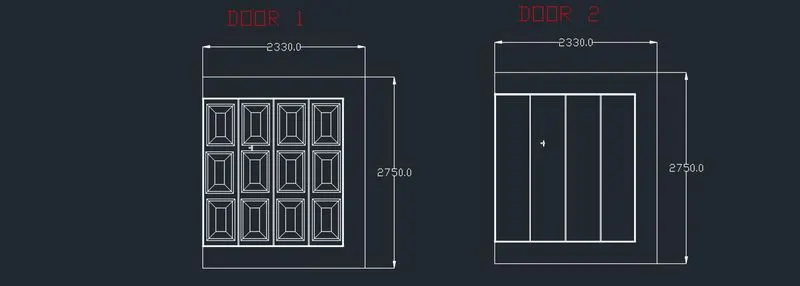
- The 1st step is drawn a recatangle of given size 2330x2750
- Then the door portion is drawn and using the offset option the boundaries of the door are drawn.
- The projection designs of the door are drawn by drawing a rectangle of required size.
- Then using the offset option the interior design are drawn and coverted into a block.
- Then it is inserted inside the door using the insert option at periodic intervals.
- Then a definite dimension and text style is fixed and the dimensions are marked and markings such as Door 1 is given
- For Door 2 the Door 1 is copied and the design projections are trimmed off as it is a normal plain door and dimension,markings are done
- Then both Door 1 and Door 2 are converted into blocks and saved for future usage.
Results: The given door diagrams are drawn and are converted into blocks sucessfully.
3. Create each symbol as a block with the name given in the legend. After creating the blocks arrange them in the legend as shown in the Figure.
Aim: To Create each symbol as a block with the name given in the legend and use attributes for the name and to create a table with blocks as shown in the diagram.
Introduction: The given diagram consists of electrical symbols and their names. The table is prepared and given with the diagram of the electrical plan of the building to have the better understanding for the comman man. The symbols are created and converted into blocks and are arranged in table as per the given figure.
Steps:
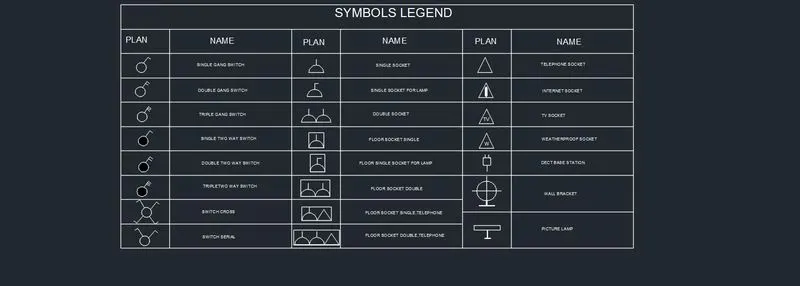
- The 1st step is to create the symbols given as per the order
- For each symbols different commands are used.
- For Switches a circle is drawn and a line is drawn at an inclined angle.
- Then for double,triple switch it is copied and modifications are done as per the symbols.
- For two way switched hatch is done inside the circle as per the given sybol
- Then for socket symbol a circle is done and half of the circle is trimmed and a line is drawn at the top in the middle so as to look like a semicircle.
- Then it is copied and further modifications are done for the proceeding symbols.
- For Telephone socket a traingle is drawn and for Internet it is copied and a line is inserted on the middle and the line weight is changed
- For TV and Weather proof socket triangles are drawn and text are added respectively
- For wall bracket a circle is drawn and four lines are drawn and it is mounted on a line
- For picture lamp rectangles are drawn and are connected as per the symbol.
- Then using the block command all the symbols are converted into blocks.
- Then a table is created of rows and columns as per requirement
- A definite text style is fixed before entering the legend of the table using mtext command.
- Then the names of the symbols are defined as attribute using the attdef command and converted into block
- Then both symbols and names are inserted using the insert command into the table and the legend is finished.
Results: The given electrical symbols are created and converted into blocks and attributes for the names are defined succesfully and it is inserted into the table and the given symbols legend table is created and the whole legend table is converted into block and saved.
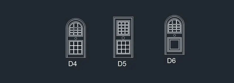
4. Create the door type for residential building as a block. Save the name of the blocks as type. Use given dimensions or assume dimensions as per industry standards.
Aim: To Create the door type for residential building as a block as per the given dimensions.
Introduction: The given diagram consists of six types of doors for residential buidlings each being of different sizes and design. The doors are drawn using the rectangle,line,circle and offset commands.
Steps:
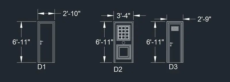
- The first step is to setup the units in imperial system as the given dimensions are feet and inches
- For door 1 a rectangle of 2'-10"x6'-11" is drawn and exploded using xplode option.
- Then using the offset option the sides and top of the door are offsetted to provide the projections of the door and the lock of the door is drawn using the rectangle command.
- For door 2 another rectangle of 3'-4"x6'-11" is drawn and exploded using xplode option
- Then a circle of required radius id drawn at the centre.
- Then two rectangle of required size are drawn at the top and bottom of the circle
- The for the top triangle using offset command offset is done inside to set the boundary of inside design
- Then small rectangles are drawn inside and are placed inside at periodic intervals and are offsetted to provide projections
- Then the lower rectagle is offsetted at periodic intervals as per requirement to provide projections and the door 2 is finished.
- For Door 3 same procedure of rectangle is drawn and offset is done
- For this door a ventilation like opening is given at the top hence a rectangle is drawn and offset is done and hatch command is used for providing the opening.
- For Door 4 same rectangle is drawn and a circle is drawn in top from the middle to end of the rectangle and the lower portion of the circle is trimmed off.
- Then using the hatch command projections are provided.
- Then a small circle is drawn in middle continued by a two rectangles at the top and bottom respectively
- Then small rectangles are drawn and placed at periodic intervals in both rectangles to provide design of the door
- For the top portion of the door design arc comand is used for providing design as per the door design.
- Foor D5 and D6 doors D2 and D4 is copied and modifications are done as per the given design using the rectangle and offset command.
- Then all the doors are converted into blocks using the block command.
- After defining the text and dimension style dimensions and markings are provied.
Results: The given doors are created and converted into blocks sucessfully as per the dimesnions given.
5. Create each shape as a block as shown in the Figure. Save the block and insert them on the table as shown in the Figure.
Aim: To Create each shape as a block as shown in the Figure and to insert them in a table as per the given figure.
Introduction: The given diagram consists of bar bending schedule and other details such as length,weight and hook lenght are given. These are general details given along with the steel detailing.
Steps:
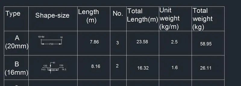
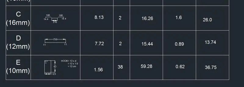
- Initially the given steel shapes are created as per the given figure dimensions using the line command and rectangle.
- The sides are given bend using the fillet command with the required radius and all of them are converted into blocks using the block command.
- Then a table of required columns and rows are created.
- Then attributes are defined using the attdef command for each detail such as length,no,weight and are convertd into blocks
- Then both steel shapes and attributes are inserted into the table using the insert command
- Then using mtext and dimlinear command dimension and markings are given in the steel shapes to provide better details and the given figure is finished.
Results: The given steel shapes and details are created,converted into blocks and a table of contents is created sucessfully.