Creating Bar Bending schedule, Different Door types, and Creation of standard drawing templates using AutoCad
CREATING BAR BENDING SCHEDULE, DIFFERENT DOOR TYPES, AND CREATION OF STANDARD DRAWING TEMPLATES USING AUTOCAD
Introduction:
BLOCKS
It includes static blocks, dynamic blocks, white block, redifining blocks, exploring blocks
A block is a collection of objects(lines, arcs, circles, text etc) that form a more complex entity that normally represents an object in the real world eg.a door, a chair, a window, a computer.
Library of blocks can be built up consisiting of the parts that you require many times in your workday. These blocks can be stored in a seperate folder and even on a network, so that all drafters have access to them. Eg: plumbing parts, valves, elbows etc. as well as electric symbols or furniture.
TO INSERT A BLOCK
- Click home tab> Block panel> Insert. Find
2. To insert a block, do one of the following:
- Select an icon or a blockname from the block definitions displayed in gallery. Click the location for the block refences.
- Click therecent Blocks option. From the Blocks palette, click and place theblock reference. You can also use the drag-and-drop method for speed, but this method doesn't use the settings specified under Insertion Options.
- Click the Blocks from Other Drawing option. From the Blocks palette, use either the click-and-place or drag-and-drop method to insert the block refernce. To choose a different drawing file, click the Browse... control and specify the drawing file
3. At the bottom of the blocks palette, choose one or more options to control the placement, scale, rotation, and automatic repetition. If you want the objects in the block to be inserted as individual objects of as a single block, select Explode.
4. Click OK
ATTRIBUTES
An attribute is a label or tag that attaches data to a block. examples of data that might be contained inan attribute are part numbers, prices,comments, and owner's names.
Attribute information extracted from a drawing can be used in a spreadsheet or database to produce a parts list or a bill of materials. Toc can associate more than one attribute with a block, priovided that each attribute has a different tag.When you define an attribute, you specify
- A unique tag that identifies the attribute by name.
- A prompt that can be displayed as the block is inserted.
- A default value that is used if a variable value is not entered at the prompt.
1.
Aim:
To create the titleblock named Custom1_titleblock (1.a) and Custom2_titleblock(1.b) using block and attributes command in AutoCAD.
Procedure:
- Initially set the units of the drawing as decimal (millimeters).
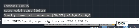
- Now, set the limits of the drawing
- Specify the lower left corner: (0,0)
- Specify the upper right corner: (50000,50000)
Custom1_titleblock:
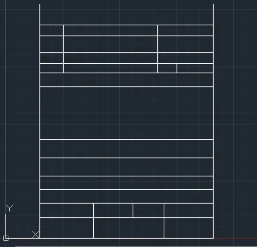
- Now, choose the line command to draw the lines to complete the table.
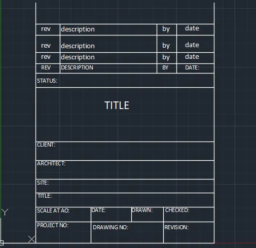
- Using the mtext command draft the texts.
- From the properties change the colour as required.
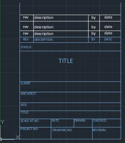
- Now, the next step is to convert it into block.
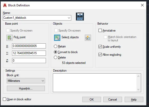
- Then click ok and it is converted into a block.
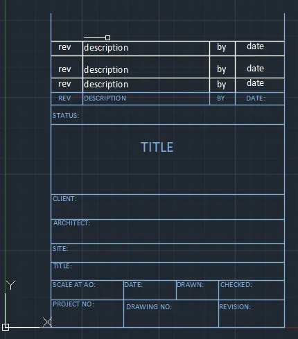
Custom2_titleblock:
- Again choose line command to draw the table.
- Using the mtext command draft the texts.
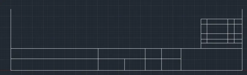
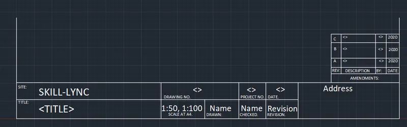
- Now, the next step is to convert it into block.
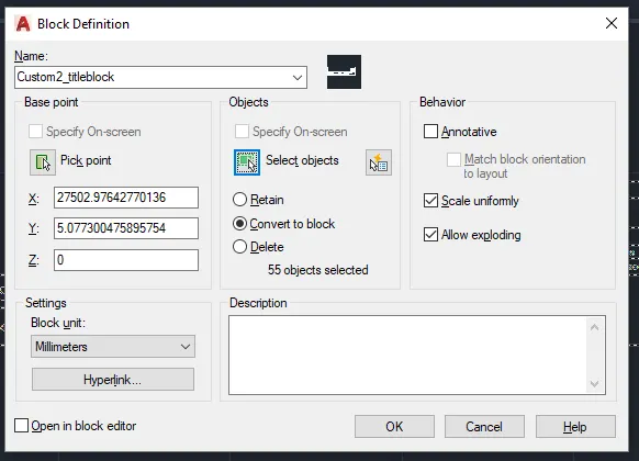
- Then click ok and it is converted into a block.

2.
Aim:
To create the door types for warehouse and to convert the same into blocks.
Procedure:
- Initially set the units of the drawing as decimal (millimeters).
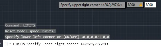
- Now, set the limits of the drawing
- Specify the lower left corner: (0,0)
- Specify the upper right corner: (8000,8000)
Door 1:
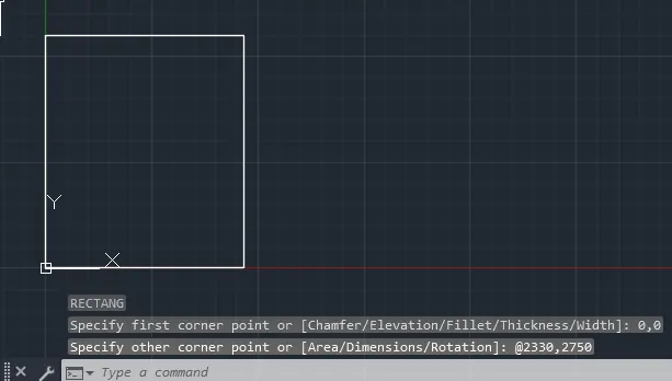
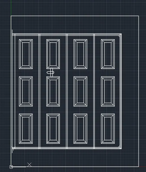
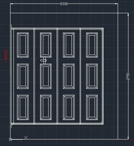
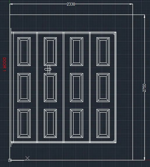
- Draw a rectangle using the command rec having dimension 2330mmx2750mm.
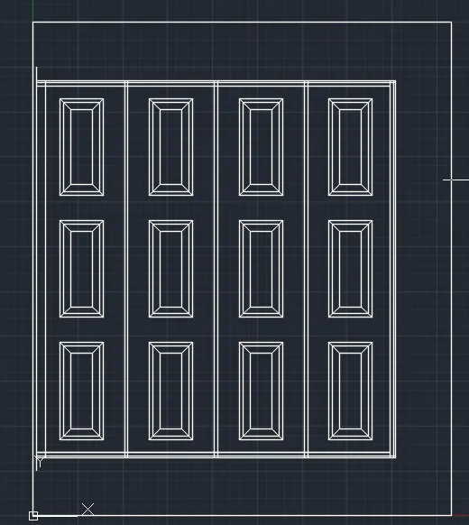
- Now, using the line and offset command draw the panels of the door.
- Now, we have to create the lock for the door, which created separately.
- This can be created using rectancle and fillet command.
- Then convert it to a block.
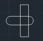
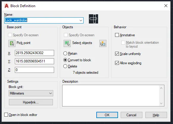
- Now, place this lock on door at appropriate position.
- Now, provide the dimensions to complete the figure.
- Now, we have to convert this door to a block. So for this, type block in command prompt and do the necessary steps to convert to block.
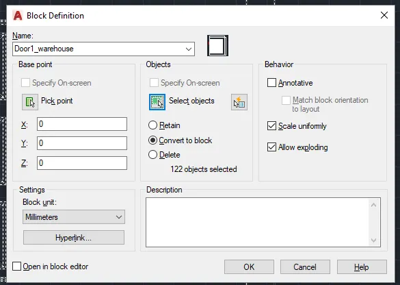
- Then click ok and it is converted into a block.
- Hence, the block has been created.
Door 2:
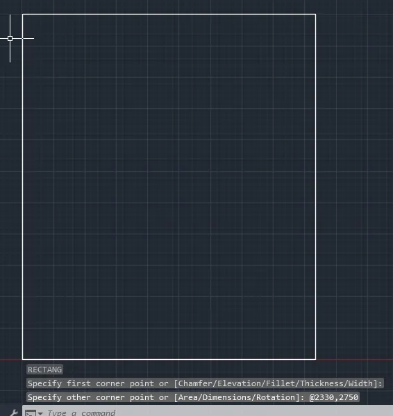
- Draw a rectangle using the command rec having dimension 2330mmx2750mm.
- Now, using the line and offset command complete the door.
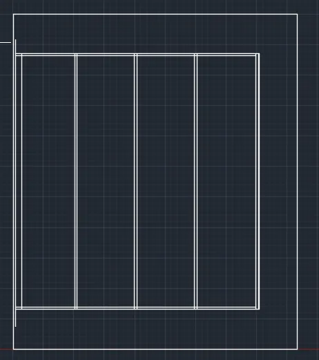
- Now, place the lock that is previously created in the current drawing by insert block option.
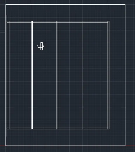
- Now provide the dimensons and text to complete the drawing.
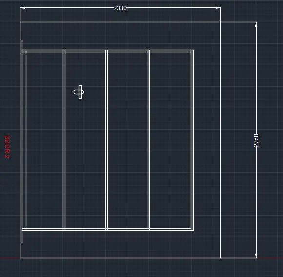
- Now, we have to convert this door to a block. So for this, type block in command prompt and do the necessary steps to convert to block.
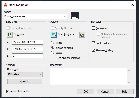
- Then click ok and it is converted into a block.
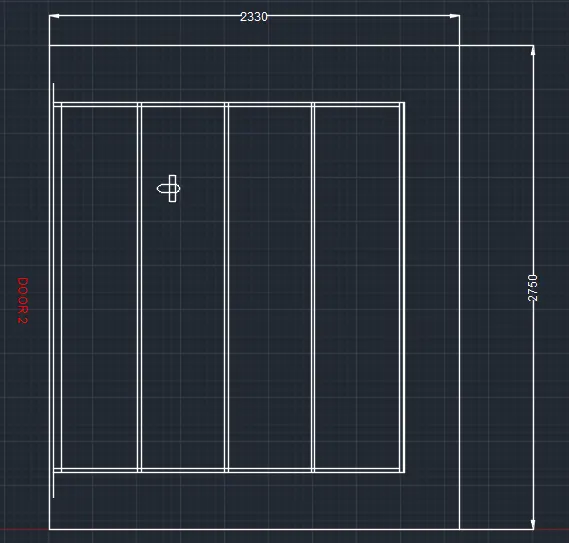
- Hence, the block has been created
3.
Aim:
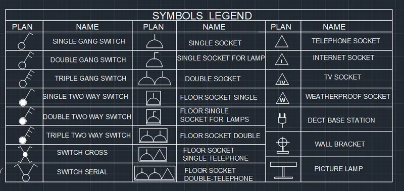
To create a symbol legend with each symbol as a block with the name .
Pocedure:
- Initially set the units of the drawing as decimal (millimeters).
- Now, set the limits of the drawing
- Specify the lower left corner: (0,0)
- Specify the upper right corner: (5000,5000).
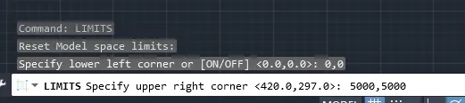
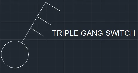
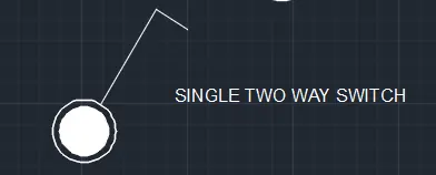
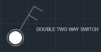
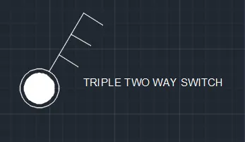
- Inorder to create a symbol legend, first of all create all the symbols individually and then convert them into blocks.
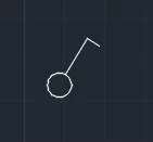
- Now, first one is single gang switch, so for that type c to draw a circle, type L to draw line.
- After drawing convert it into a block.
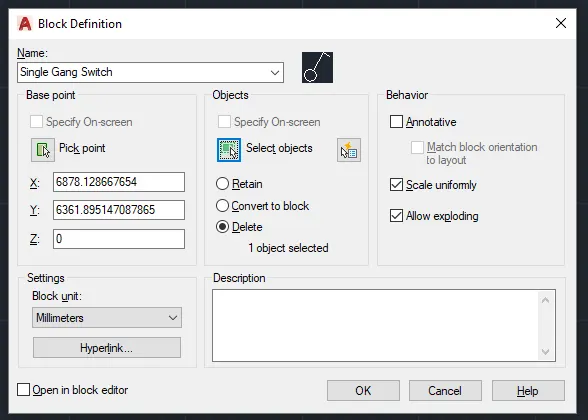
- Hence it is converted to a block.
- Similarly convert all the symbols into bocks after drafting.
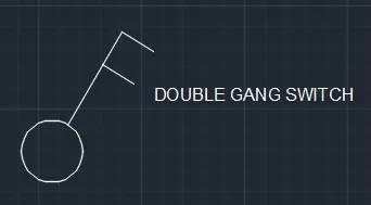
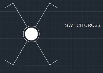

- To draw lines use command L.
- To draw an arc, type arc in the command prompt.
- To draw rectangle or square choose command rec.
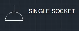
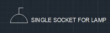
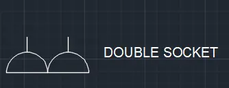
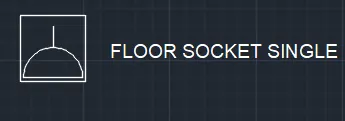
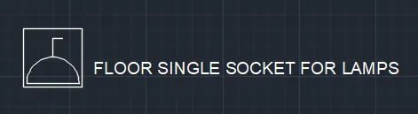
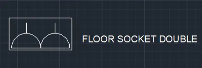
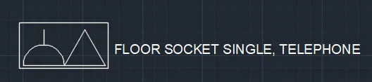

- Use command L to draw triangles.
- Command rec to draw rectangles.
- Mtext to place texts.
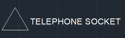

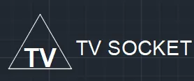
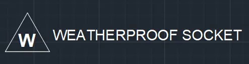
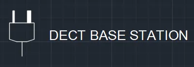
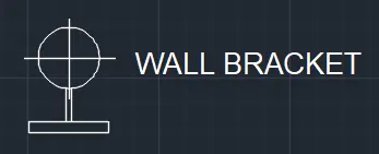
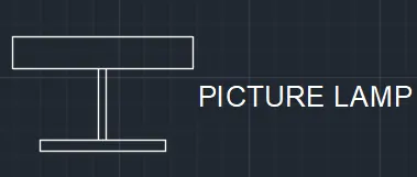
- Hence, all symbols have been converted to blocks.
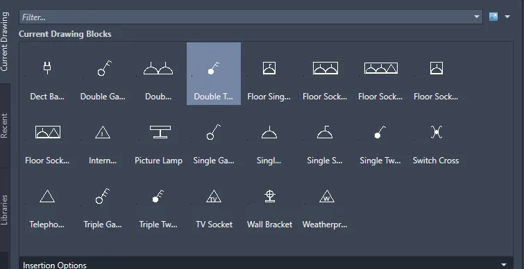
- Now, these symbols has to be inserted into a table along with their names.
- Inorder to draw a table use line command and complete the table.
- Then insert the blocks and their names into the table.
- Names can be inserted from the field option in insert tab.
4.
Aim:
To create the door types for resisdential building as a block.
Procedure:
- Initially set the units of the drawing as Architectural (feet and inches).
- Now, set the limits of the drawing
- Specify the lower left corner: (0,0)
- Specify the upper right corner: (100',100').

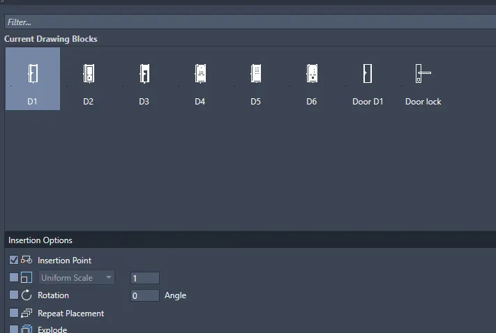
1. D1
- Choose line command and draw the outline of the door.
- Choose offset command and complete the door.
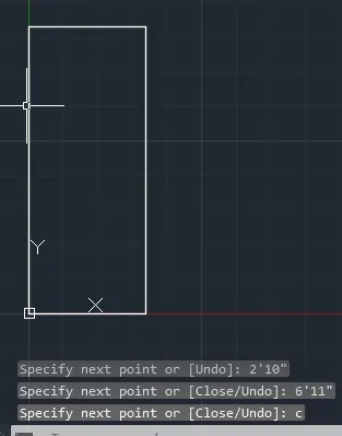
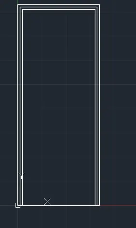
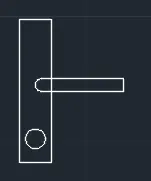
- Now create the lock for the door using circle rectangle line and arc option.
- After drafting convert it into a block.
- Then place it within the door.
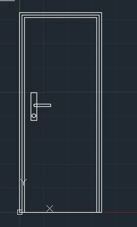
- Now, provide the dimensions and text.
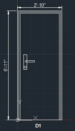
- Now, convert this door to block named Door D1.
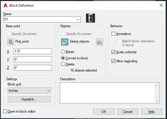
- Click ok and then the entire door is converted to block.
- Hence, the block created is given below:
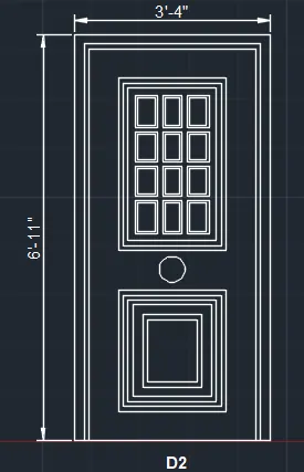
2. D2
- Again choose line command and draw the out line of the door.
- Then using the offset command draw the panels of the door.
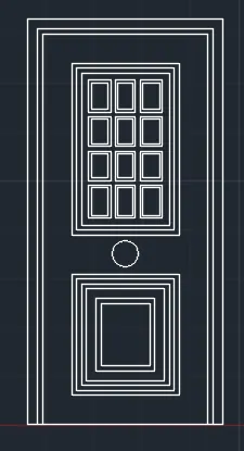
- Provide the necessaary dimensions and texts.
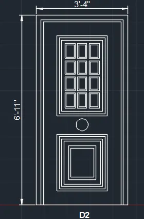
- Now, we have to convert the door so created into block and is named as D2.
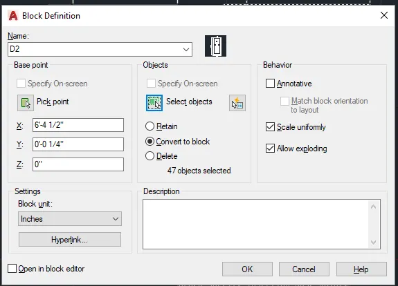
- Then click ok, so that it is converted to block.
- The block hence created is given below:
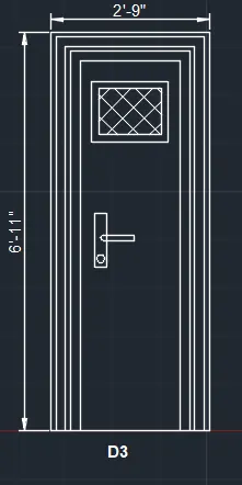
3. D3
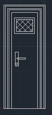
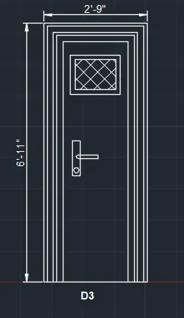
- Using line command draw the outline of the door.
- Within the center portion of the rectangle hatching is provided.
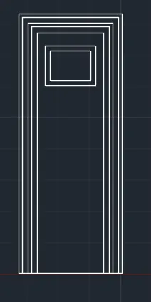
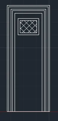
- To place the lock in the door, the previously created bock can be utilised.
- Now, provide the texts and dimensions to the doors.
- Now, convert the door so created to block.
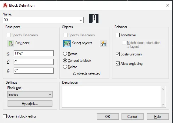
- Then click ok, so that it is converted to block.
- The block hence created is given below:
4. D4:
- Initially, choose line command an draw an outline of door.
- Then choose arc and make the top portion of the door curved.
- Then using the offset command complete the panels of the door.
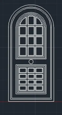
- Trim the bottom unwanted lines.
- Now, provide the dimensions and texts .
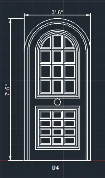
- Convert the above door to block.
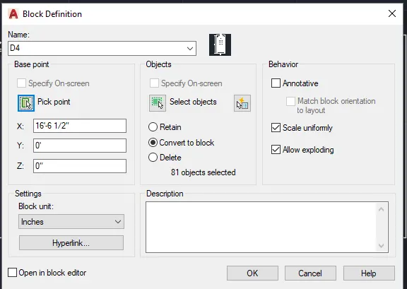
- Then click ok, so that it is converted to block.
- The block hence created is given below:
5. D5
- Using line command the outline of the door can be created.
- Then by using offset and trim command the entire panels of the door can be created.
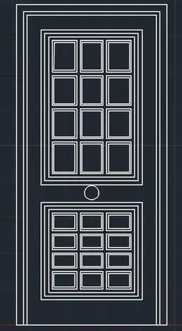
- Now, provide the dimensions and texts.
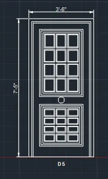
- Now, convert this figure to block.
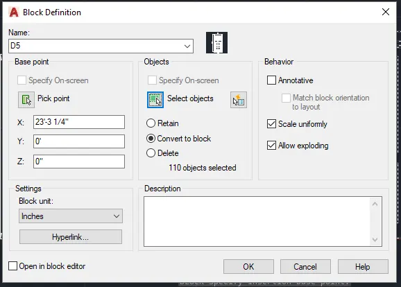
- Then click ok, so that it is converted to block.
- The block hence created is given below:
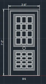
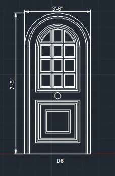
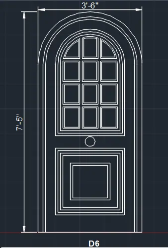
6. D6
- Inorder to draw this door, copy the D4 door and the explode it.
- Then in the bottom rectangular panel of the door is altered to obtain the door D6.
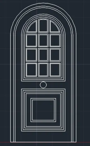
- Now, provide the dimensions and texts.
- Now, convert the above created door to a block.
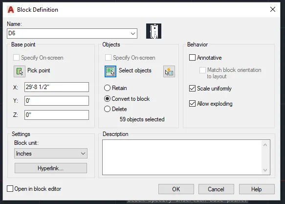
- Then click ok, so that it is converted to block.
- The block hence created is given below:
- Hence, all the doors have been created as blocks.
5.
Aim:
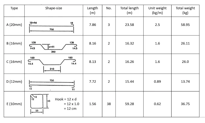
To create each shape as a block as shown in the figure and insert these blocks into the table as shown below:.
Procedure:
- Initially set the units of the drawing as Decimal (meters).
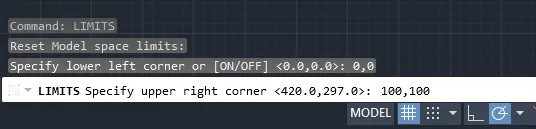
- Now, set the limits of the drawing
- Specify the lower left corner: (0,0)
- Specify the upper right corner: (100,100).
- Choose line command to draw different types of reinforcements in the bar bending schedule.
- Fillet command can also be used to draw the curves.
- Initially create individual shapes and then after providing necessary dimensions, convert them into blocks.
- The first bar is created as given below:
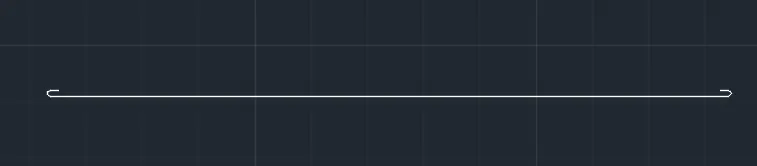

- Now, convert this into blocks .
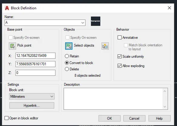
- Then click ok, hence it is converted to blocks.
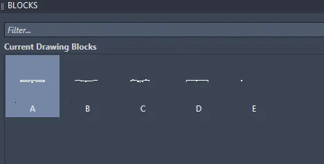
- Similarly convert all the shapes to block.
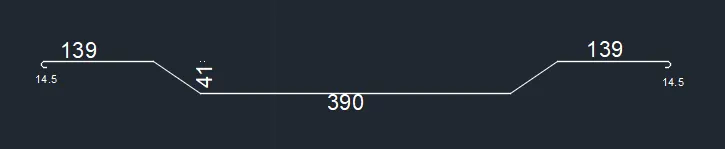
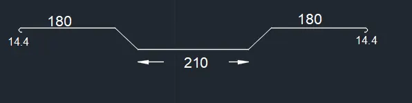

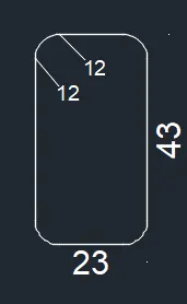
- The above drawn shapes are converted to blocks.
- Since the blocks have been created, now create the table from the annotation tab having 6 rows and 7 columns.
- Then place these blocks into the table so created after appropriate scaling.
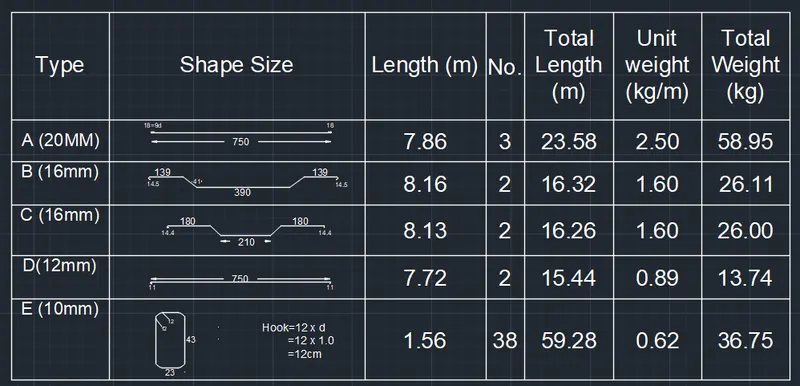
- Hence, it is completed.
Result:
1. The two templates created are given below:
(a)Custom1_titleblock
1. (b) Custom2_titleblock
2.The door types for warehouses has been created as below:
3. Symbol legend created is as follows:
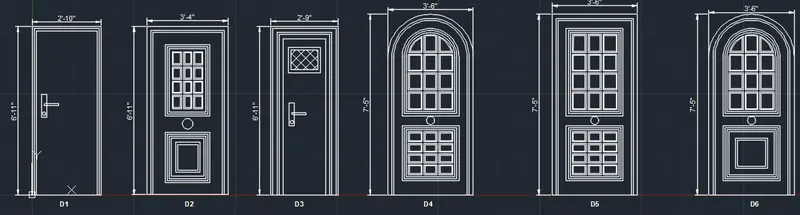
4. Different door types for residential buildings is created as below:
- D1
- D2
- D3
- D4
- D5
- D6
5. The bar bending schedule created using the blocks concept :