Creating Architectural and Structural model with 3D rendering using REVIT
-1) Select the type of structure you want to build from one of the three below:
a. Multi-Unit Residential Apartment
b. Office Buildings
c. School
AIM & INTRODUCTIOM : One out of Multi-Unit Residential Apartment,Office Buildings Or School is required to be selected to be built.
PROCEDURE IN DETAIL : I would like to build Multi-Unit Residential Apartment. In this both Architectural as well as Structural model will be created. In Architectural model elements like doors, Windows, Topographical featurea , Furnitures etc will be created while in Structural model components like footings, columns , beams, slab etc will be created.
RESULT : Explaination of Q-1 ia as explained above.
-------------------------xxxxxxxxxxxxxxxxxxxxx----------------------------xxxxxxxxxxxxxxxxxxxx--------------
Q-2) Assume reasonable assumptions for geographic and location details for your project modeling. Based on assumptions and type of structure selected identify the modeling requirements from NBC.
AIM & INTRODUCTIOM : Modelling requirement as per NBC guide lines based on structure type, geographic location are to be identified.
PROCEDURE IN DETAIL : Building height is more than30 m
As per NBC guidelines :
- One Fire lift per 1200 sqm floor area is required to be provided with loading capacity of 8 persons
- Passenger lift need to be provided
- Building Height is more than 30 m, Group B, C, D, E & F Occupancy will not be permitted
- All material of constructions in load bearing elements , stairways and corridors and facades shall be non-combustible.
- Internal walls or staircase shall be of brick or RCC with fire rating of minimum 2 hour.
- There shall be a control room at the entrance floor of the building with communication system
- Height of the Kitchen shall not be less than 2.75 m.
- Height of bath room shall not be less than 2.1 m
- Aare of the habitable room shall not be less than 9.5 sqm.
- Area of the kitchen where seprate dining area is provided shall not be less than 5 sqm with minimum width of 1.8 m.
- Area of bath room shall not be less than 1.8 sqm with minimum width of 1.2 m. The floor area of the WC shall be 1.1 sqm with a minimum width of 0.9 m. If bath and WC are combined its floor area shall not be less than 2.8 sqm with minimum width of 1.2 m
- Height of the plinth shall not be less than 450 mm from the surrounding ground level.
- Height of all the room for human habitation shall not be less than 2.75 m measured from the surface of the fllor to the lowest point of ceiling.
- Basement shall not be used for residential purpose.
- In a house of two rooms, first room shall not be less than 9 sqm with a minimum width of 2.5 m and second room shall not be less than 6.5 sqm with a minimum width of 2.1 m provided that total area of both the room shall not be less than 15.5 sqm.
RESULT : Requirement for Building modelling as per National Building Code has been mentioned as above as required.
---------------------------------xxxxxxxxxxxxxxxxxxxxx------------------------------xxxxxxxxxxxxxxxxxxxxxx-----------
Q 3) Using the structural model, include the following components based on the type of structure selected
a. Foundation – Isolated / Wall/Matt Foundation
b. Columns
c. Beams Connected to Columns
d. Roof Framing/ Truss
e. Floor / Decks
f. Floor Openings for Elevators and Stairs
AIM & INTRODUCTION :
Structural components such as Foundation – Isolated / Wall/Matt Foundation ( one as per building type ) , Columns. Beams Connected to Columns, Roof Framing/ Truss , Floor / Decks, Floor Openings for Elevators and Stairs are to be created using Structural template.
PROCEDURE IN DETAIL :
Creation of Structural Template :
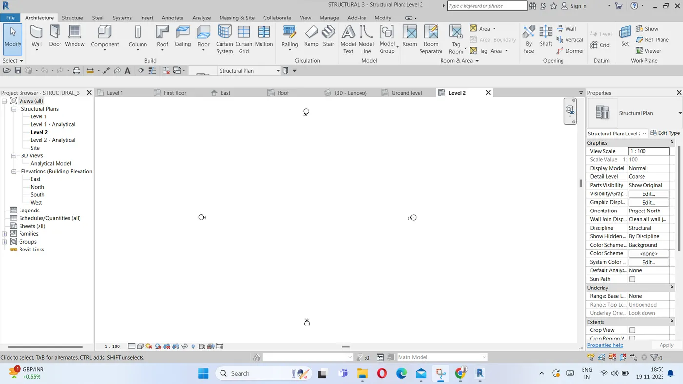
1) Open Structural template Click save as
2) Save the file into omputer with name structural as shown below-
Creation of Central Model :
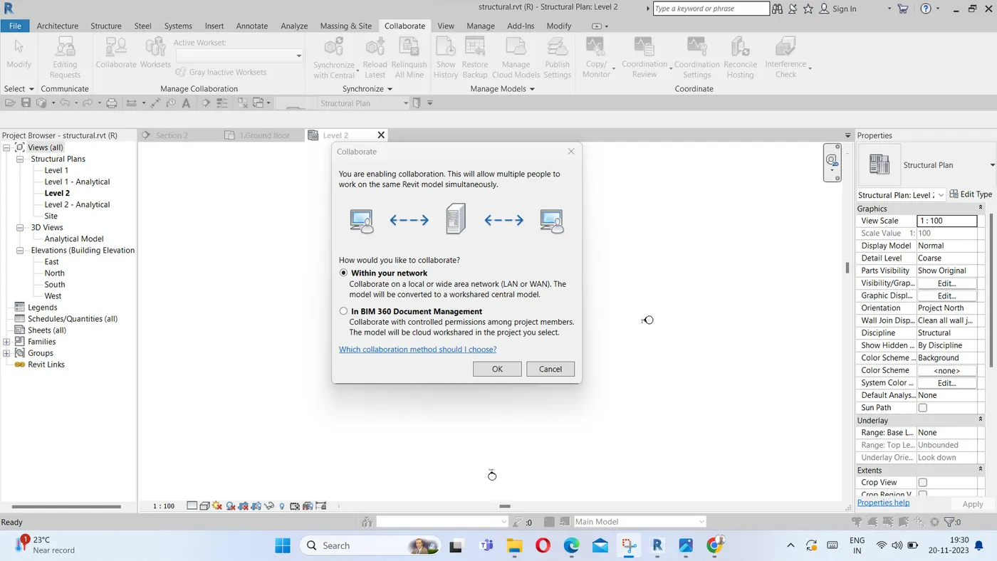
- Go to Collaborate Tab
- Click on Collaborate option and click ok
- Save the file as central model as shown below-
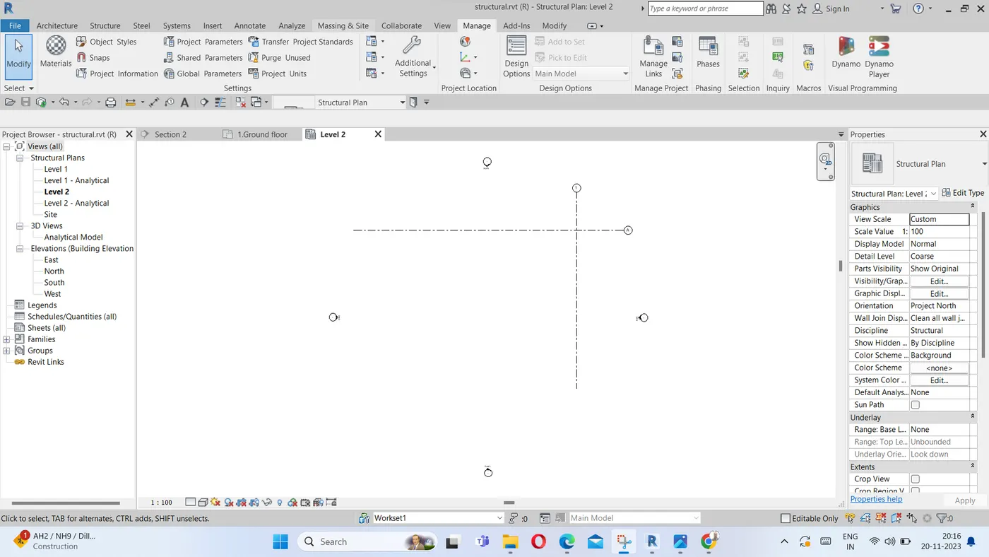
- Go to Archetectural tab
- Click Grid option for creating horizontal and vertical grid lines as shown below-
Creation of Reference datum to the Oroject :
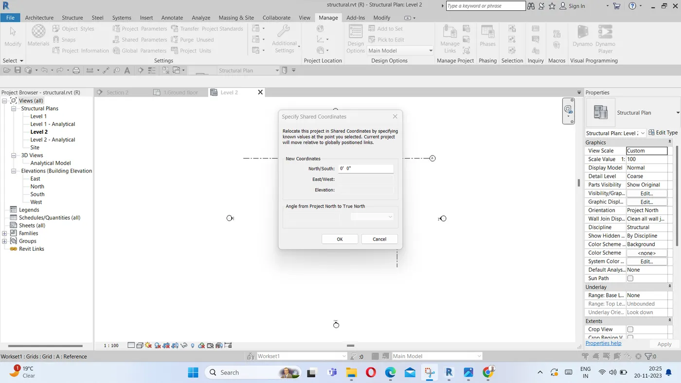
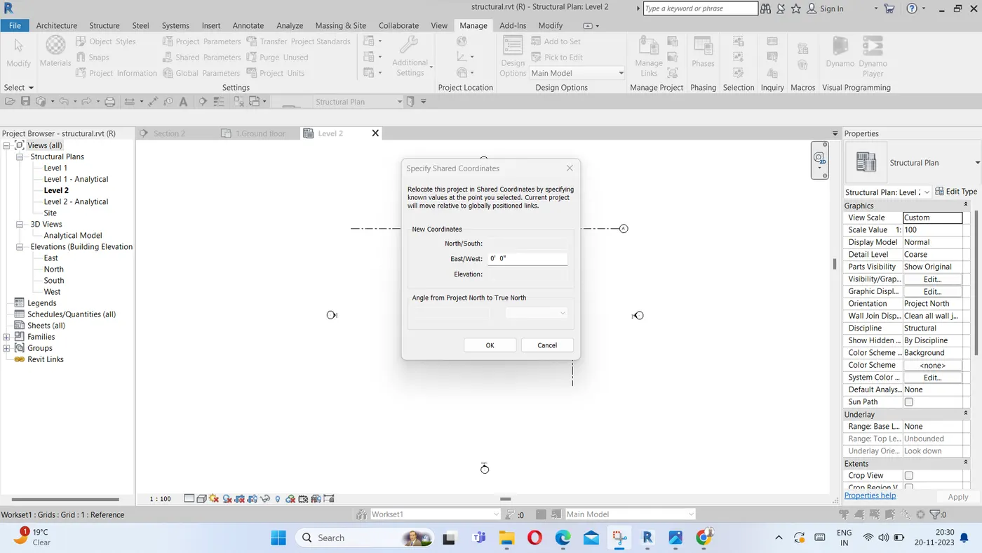
- Go to Manage Tab'
- Click on specify coordinate at a point option from drop down menu of coordinate
- Click horizontal grid and specify 0 as reference datum of N-S line of the projectas shown below-
- Click on specify coordinate at a point option from drop down menu of coordinate
- Click vertical grid and specify 0 as reference datum of E-W line of the project as shown below-
Level Creation :
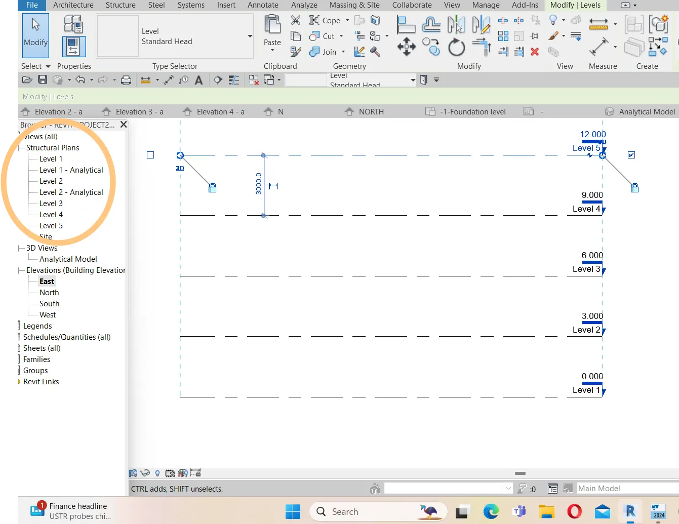
- Go to Structural tab
- Select any elevation view
- Click on Level
- Draw level as per requirement as shown below
Creation of Grids:
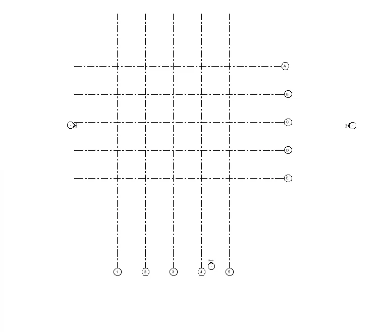
- Go to structure
- Click Grid option
- draw horizontal and vertical grids
- Save the file into your local computer with proper name
Modelling/Creation of Structural column :
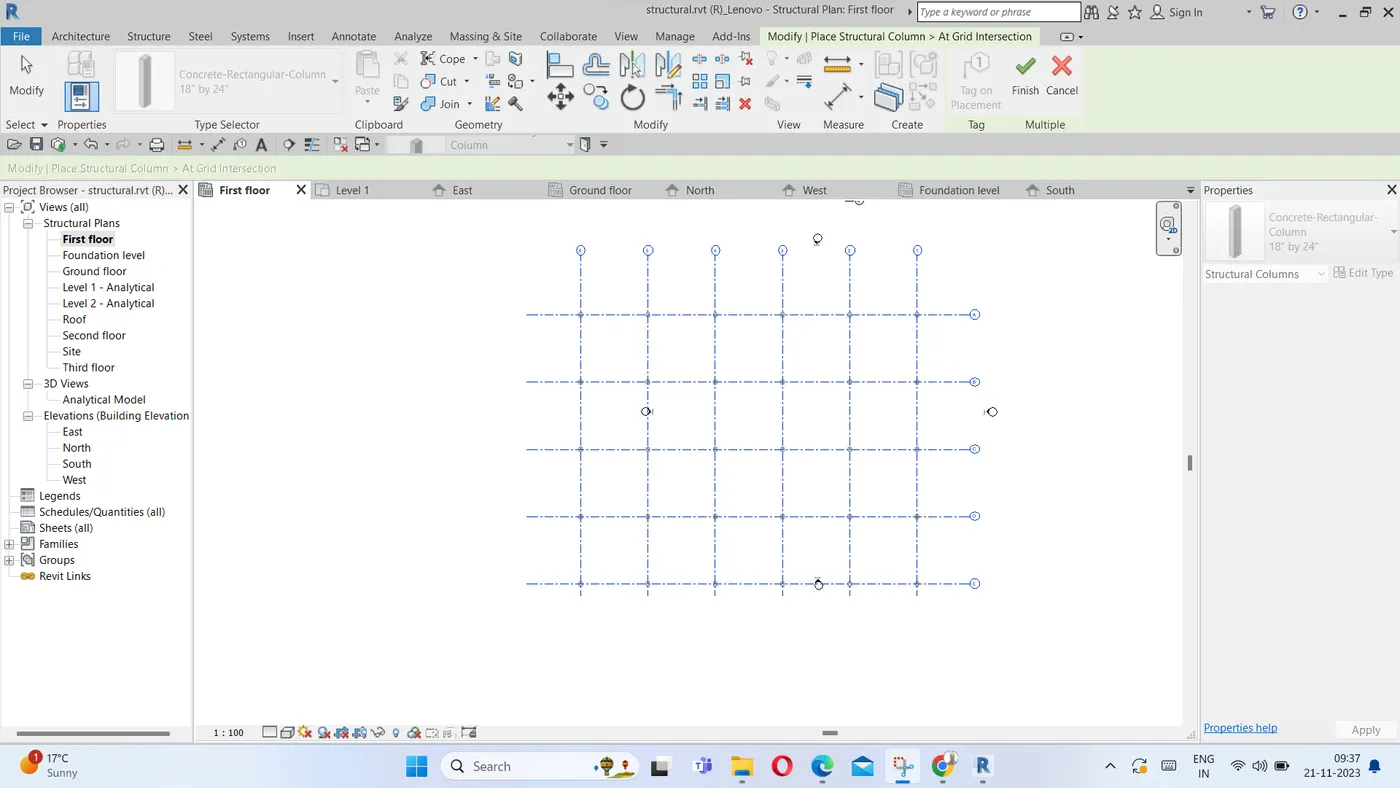
- Go to Ground floor
- Select Structural column
- Selecting Concrete column 18"x24es
- Place column at Grid by selecting horizontal and vertical grid lins
- Selct Finish
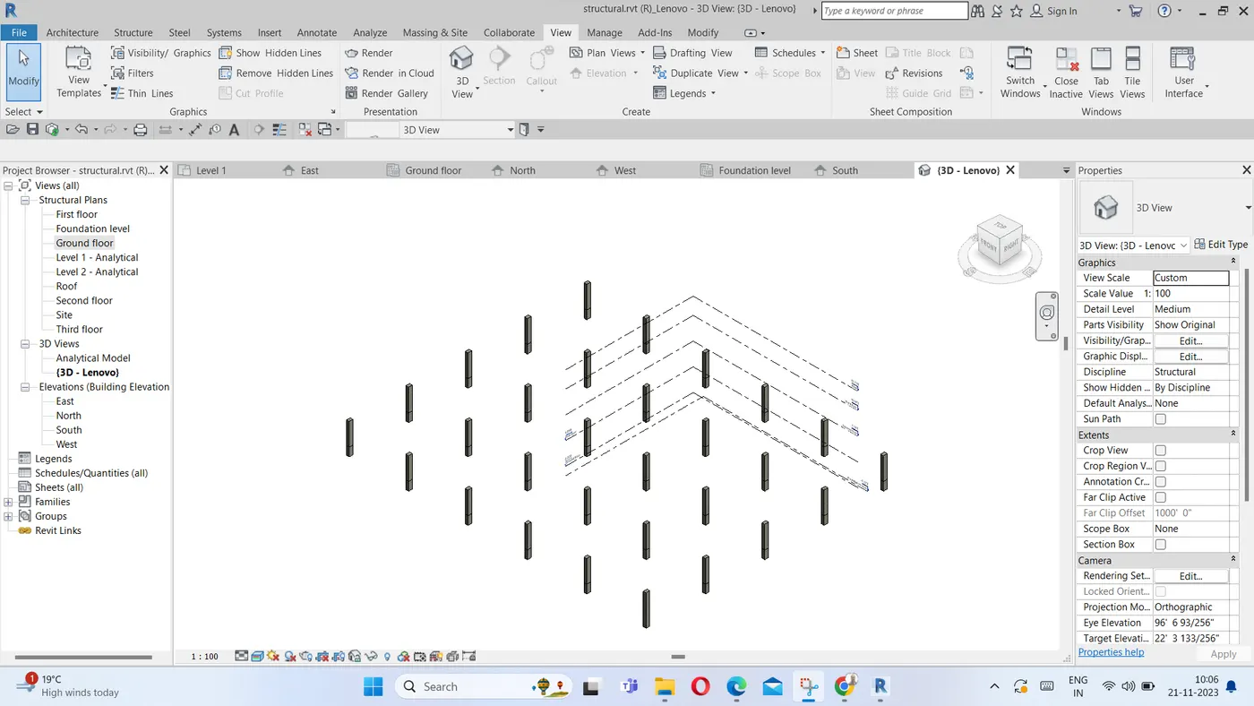
- Columns are placed between ground floor and First floor as shown belo
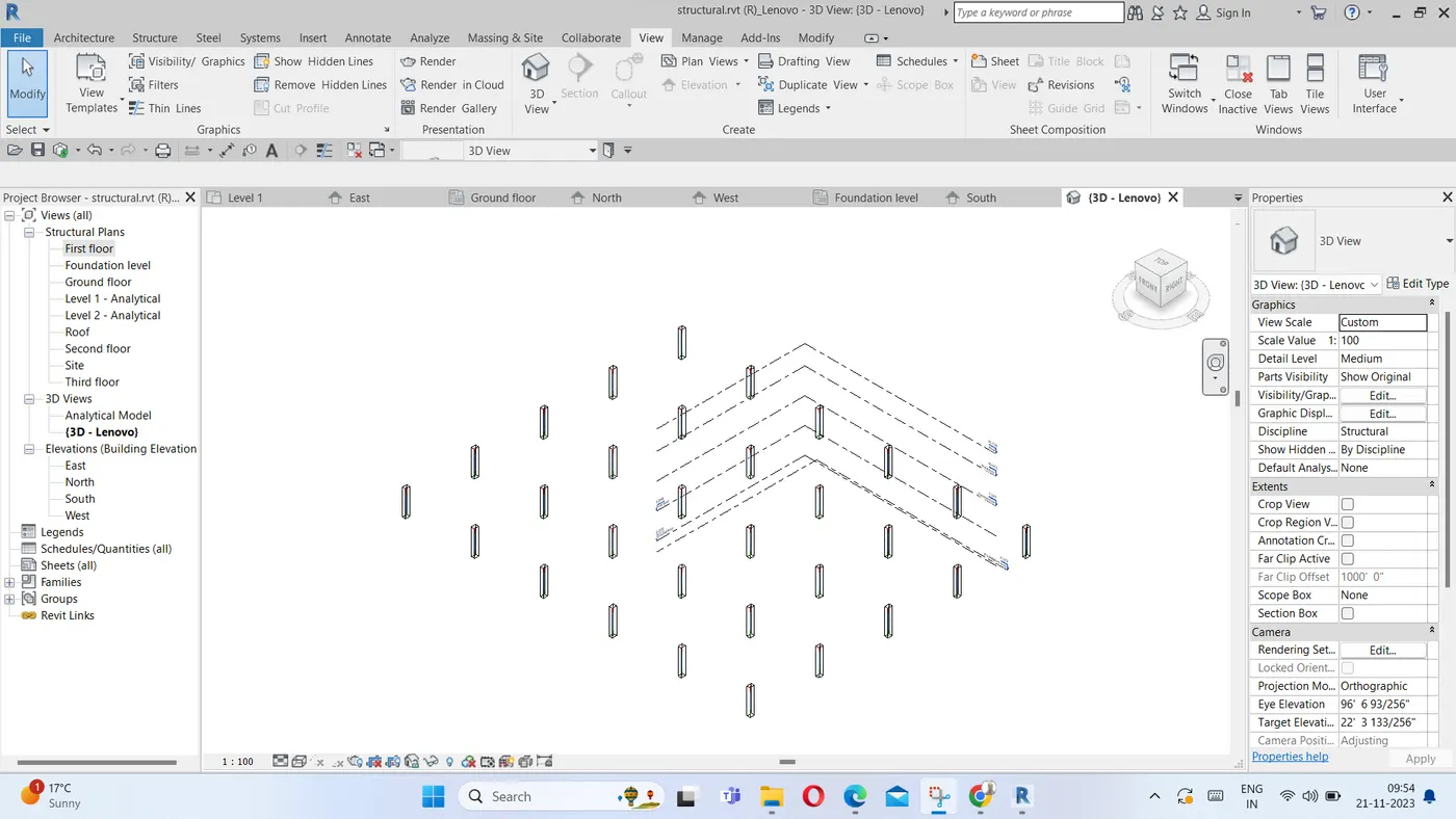
Columns have been made from foundation level to First floor level as shown below-
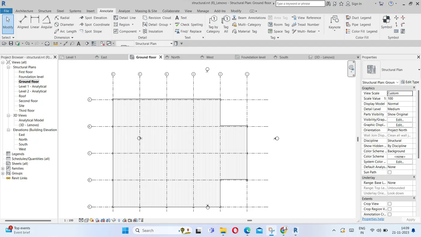
- Floor boundary is created using-
- Annotate tab and Region option then clicking Tick sign as shown below-
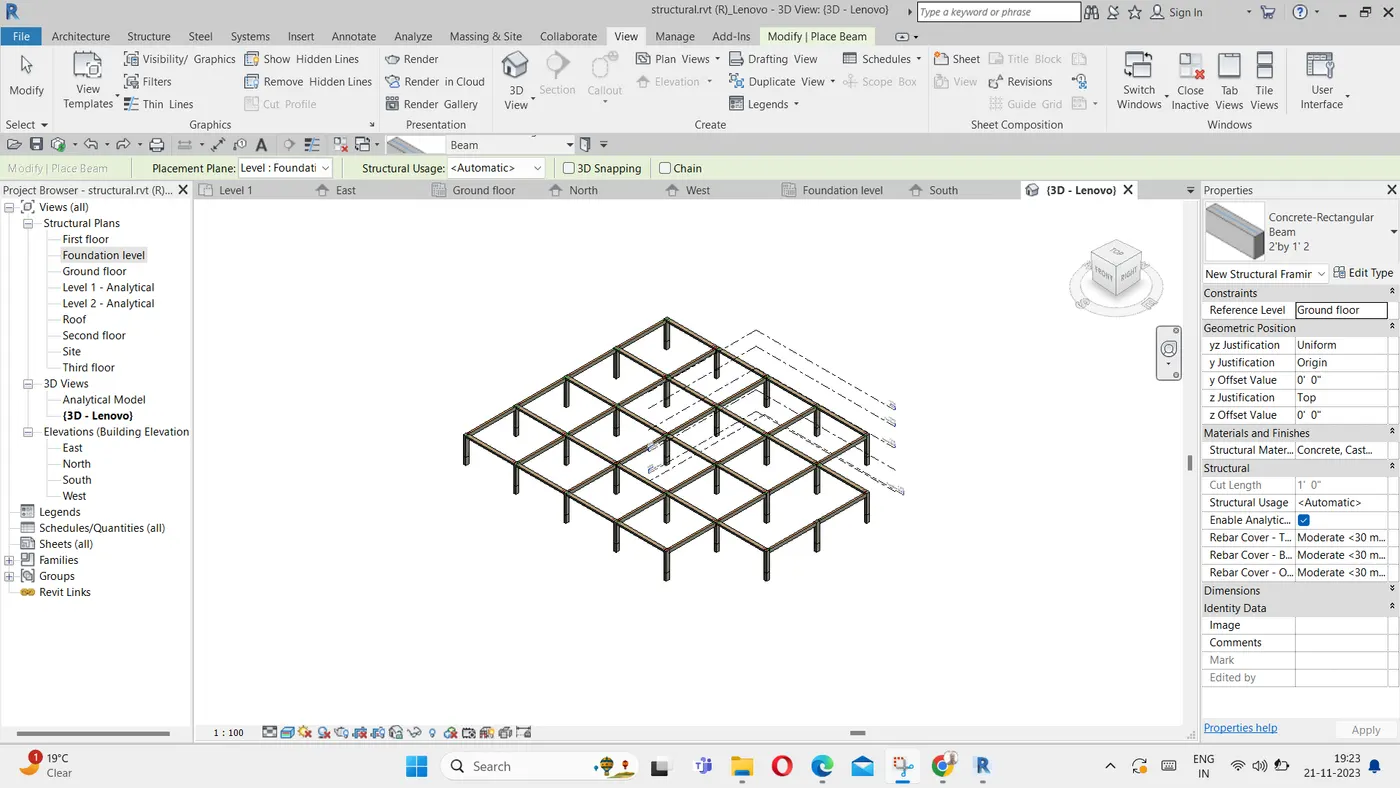
Modelling of Beams -
- Structural tab
- Beam option
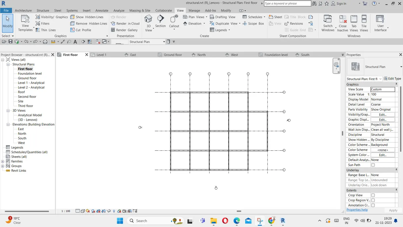
- Selecting beam type and size ( Say concrete beam of cross section 2' by 1')
- In the first floor plan join column to column to create beam network as below-
First floor plan-
3D View
Modelling foundation:
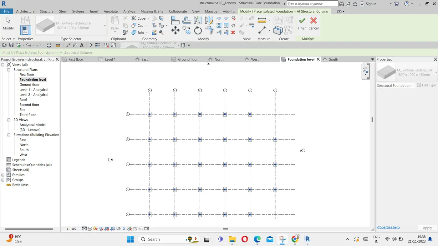
- Go to the Foundation level
- Go to the Stuctural tab
- Click Isolated Footing
- Select At Column
- Select all Columns
- Click on Finish
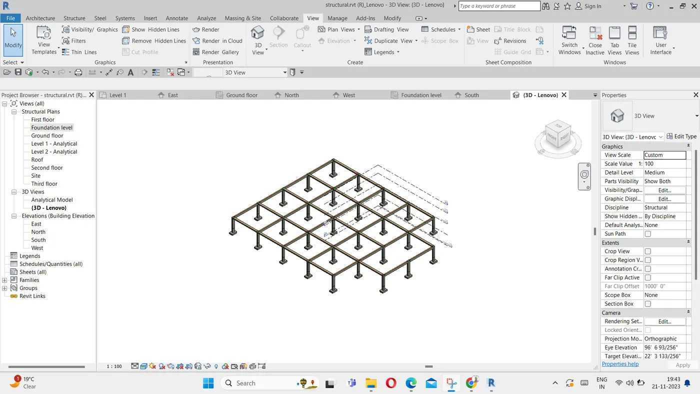
- Isolated footing for all the colums are created as bshown below-
Foundation Plan :
3D View :
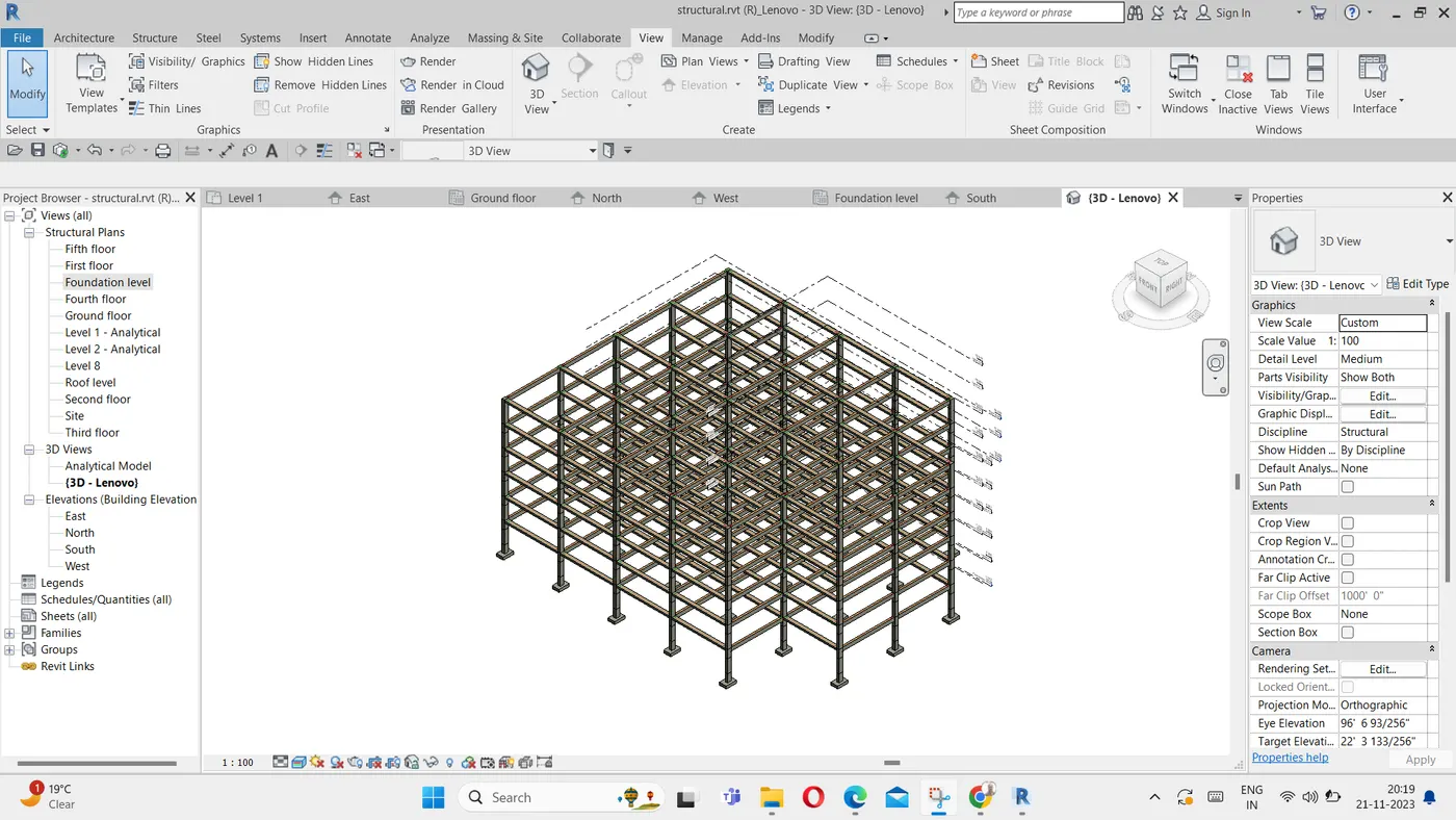
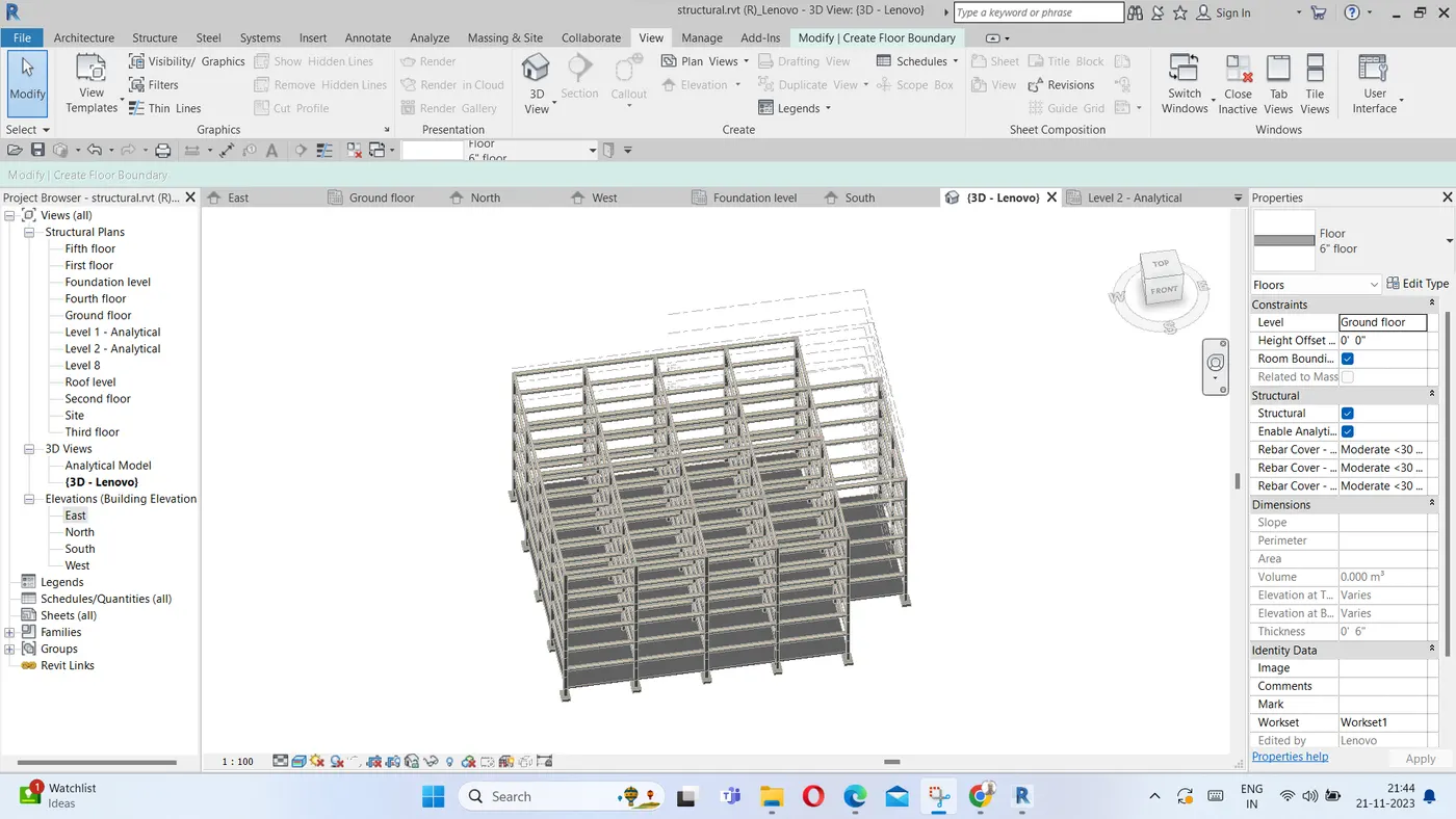
In order to create susequent stories-
- Select entire 3d elevation
- Click filter
- Uncheck footing and structural foundation
- Click on copy
- Click on Paste and select align to the select level
- Select Second, Third, Fourth , Fifth and Sisth floor
- Click OK, Structural frame work of beams and columns with sis story is created
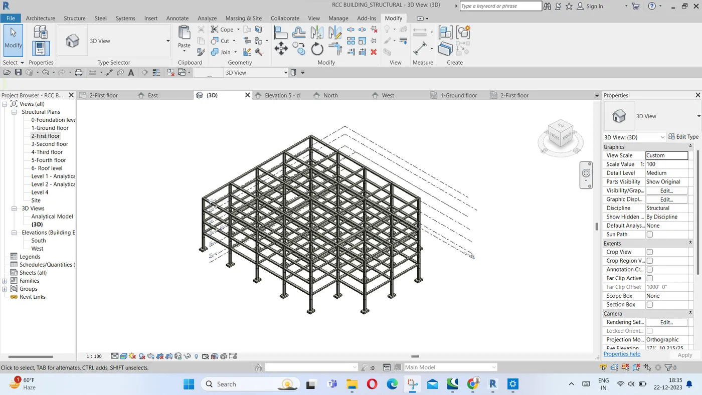
Modelling Structural floor :
- Go to Grounf Floor
- Go to structural tab
- 'Select structural floor
- Pick line and draw boundary line of floor from center to center of columns
- Click on tick mark
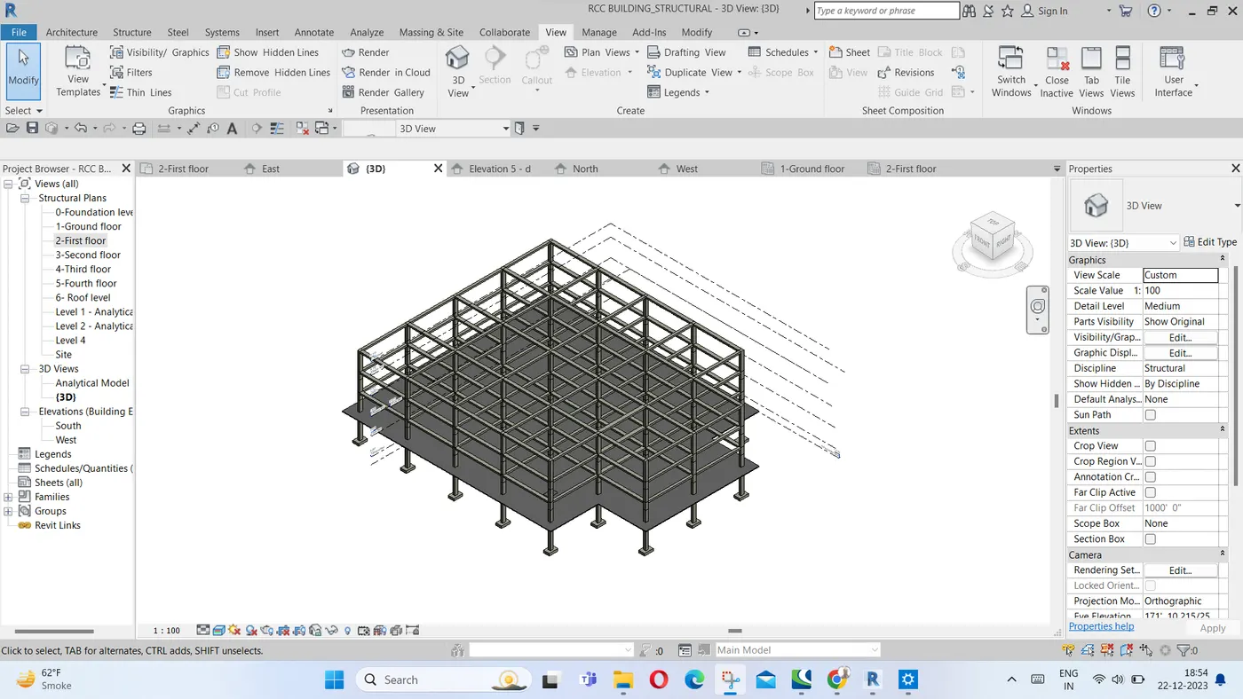
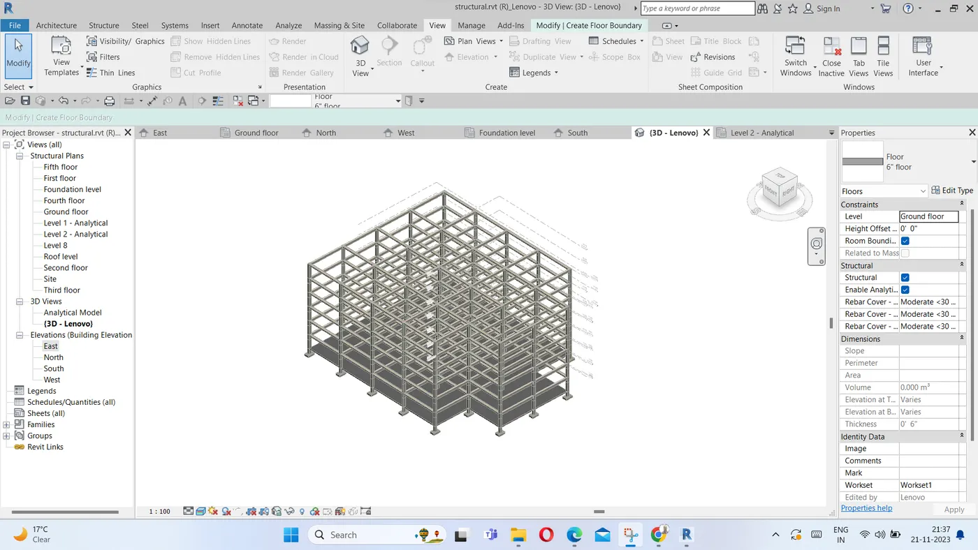
- Select Ground Floor
- Click on Copy
- Click on Paste
- Click on Aligned to the selected level
- Select floors
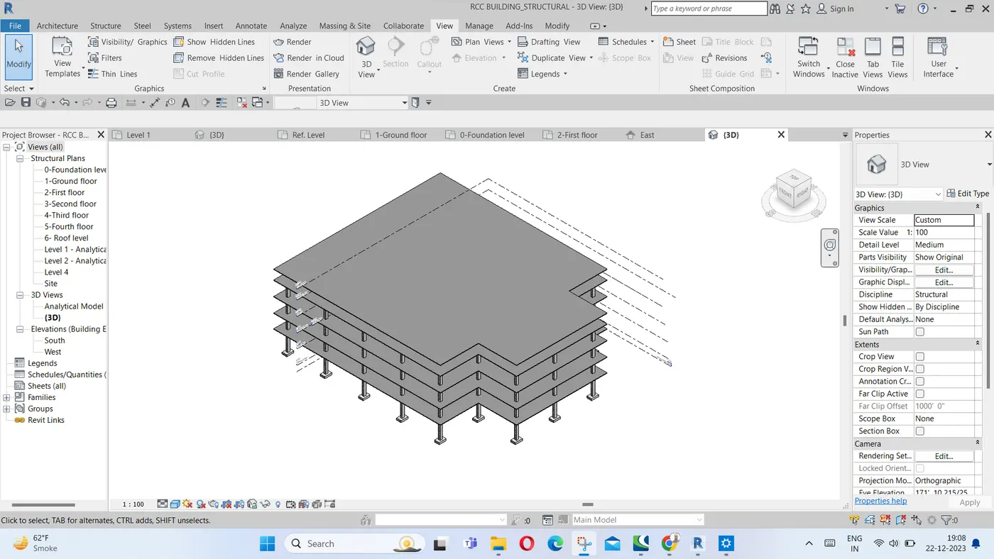
- Click OK then structural floors will be modelled on selected floors as shoown below-
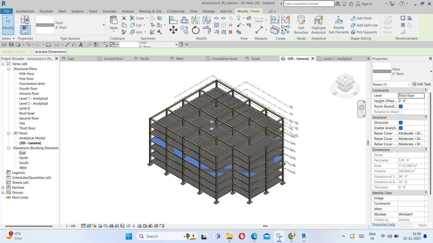
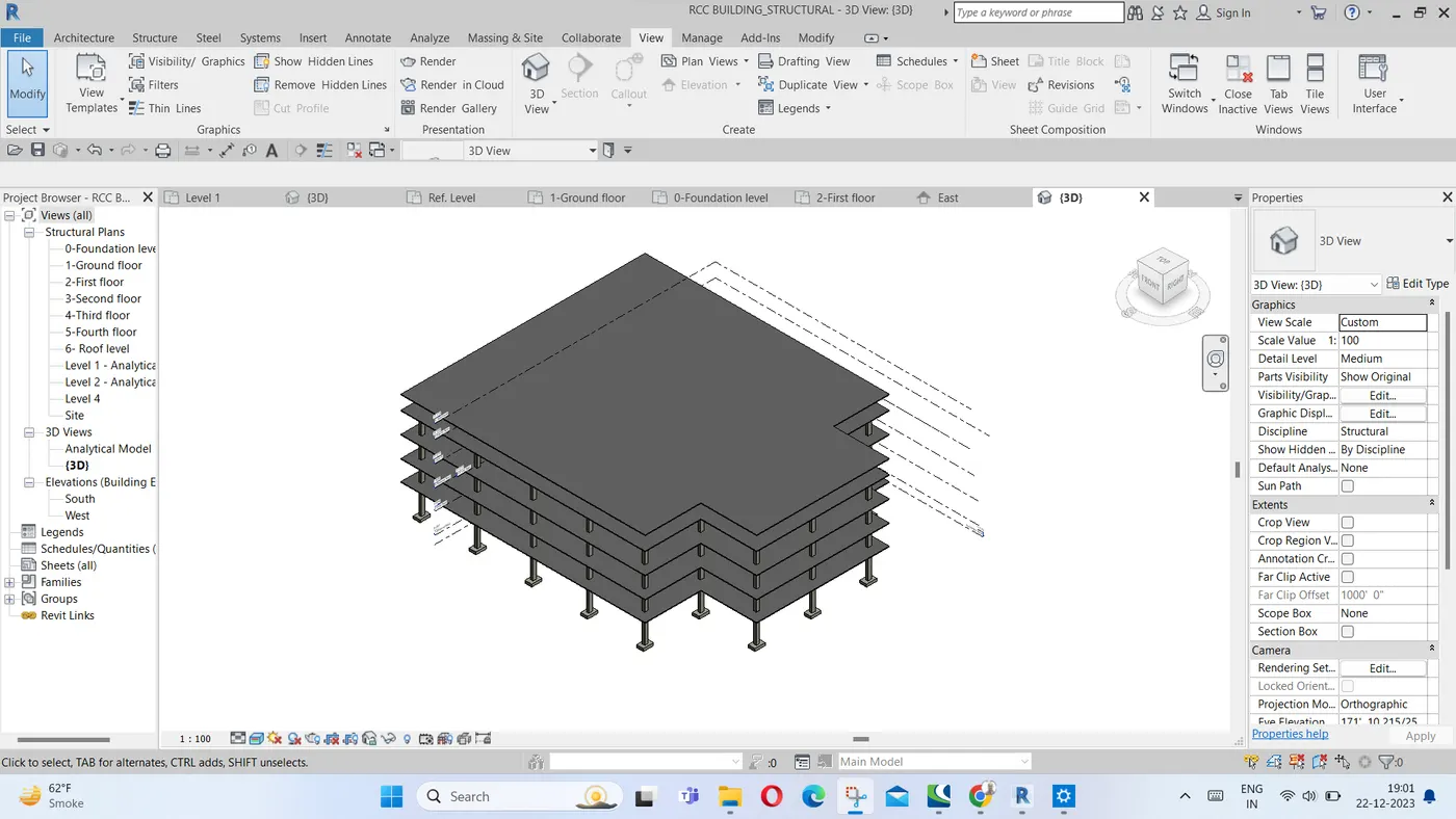
Visual style : Hidden line
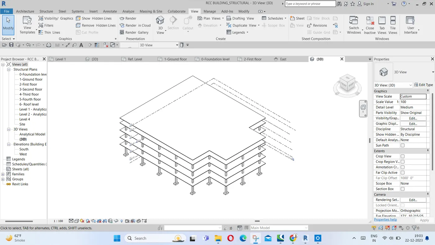
Visual style : Wire frame
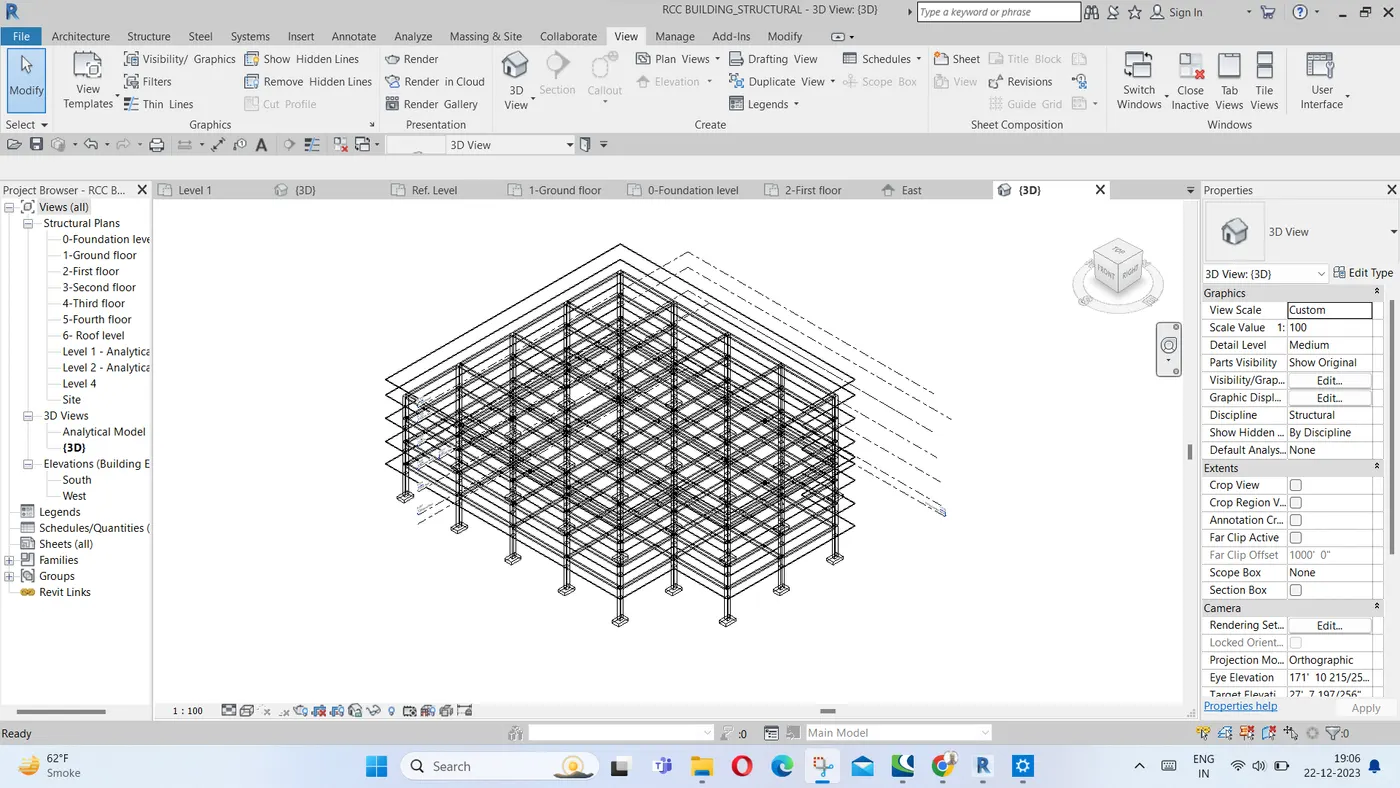
Visual style : Shaded
Opening for lift :
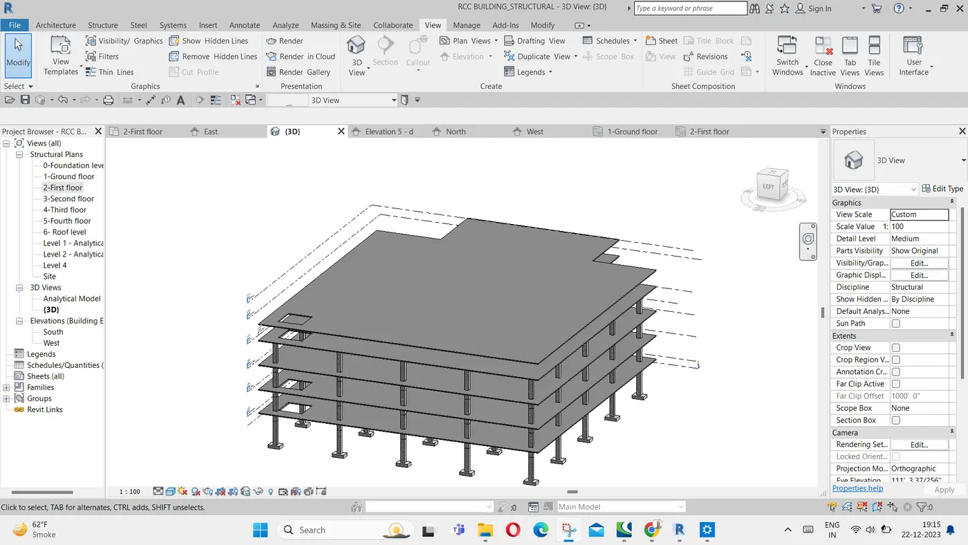
- Go to plan view
- Go to structural tab
- Click on Shaft
- Draw boundary line for lift opening
- Click on tick mark
- Go to 3D view as shown below
RESULT : Thus structural model with Structural components such as Foundation – Isolated Foundation, Columns. Beams Connected to Columns, Roof Framing/ Truss , Floor / Decks, Floor Openings for Elevators and Stairs have been created. RVT file ia attached
------------------------XXXXXXXXXXXXXXXXXXXXXX--------------------------------XXXXXXXXXXXXXXXXXXX-----------------
Q-4) Using the architectural model, include the following components based on the type of structure selected
a. Wall Layout with appropriate material and finishing
b. Exterior façade with fancy finish
c. Interior partition walls to size rooms
d. Components to add details to a room ( Desk, Chair, Lighting, Plumbing fixtures)
e. Add components such as stairs Elevators
f. Have at-least one side of the building with curtain walls and glass panels
g. Include interior and exterior lighting fixtures
h. Place proper topographic components from outside ( Trees, Parking, Plants) to add details to the model
AIM AND INTRODUCTION :
- Click project and select Architectural template
- Save the file with name Archetectural
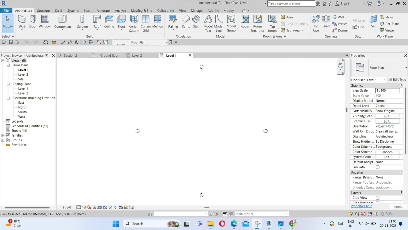
- Go to Manage Tab'
- Click on specify coordinate at a point option from drop down menu of coordinate
- Click horizontal grid and specify 0 as reference datum of N-S line of the projectas shown below-
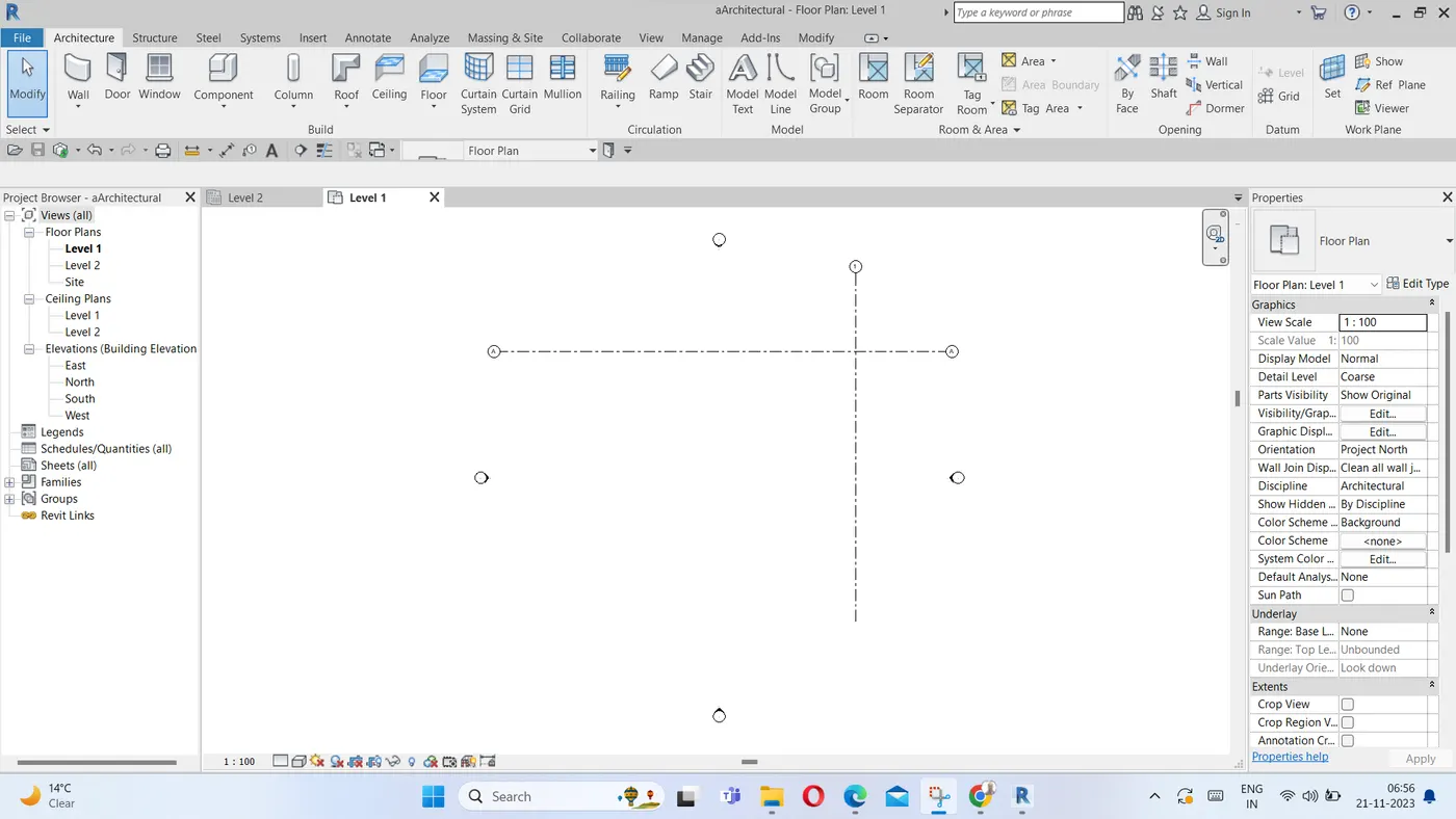
- Click on specify coordinate at a point option from drop down menu of coordinate
- Click vertical grid and specify 0 as reference datum of N-S line of the projectas shown below-
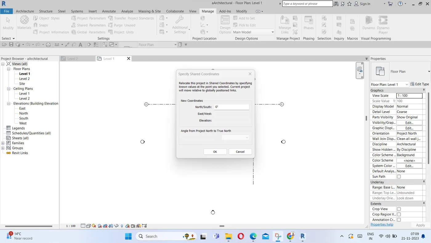
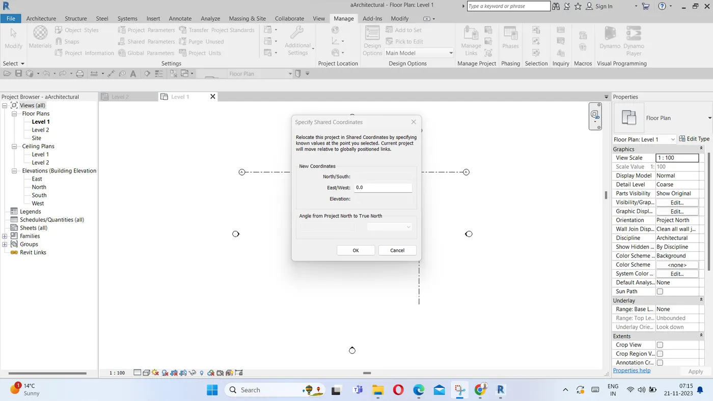
- Click on specify coordinate at a point option from drop down menu of coordinate
- Click vertical grid and specify 0 as reference datum of E-W line of the projectas shown below-
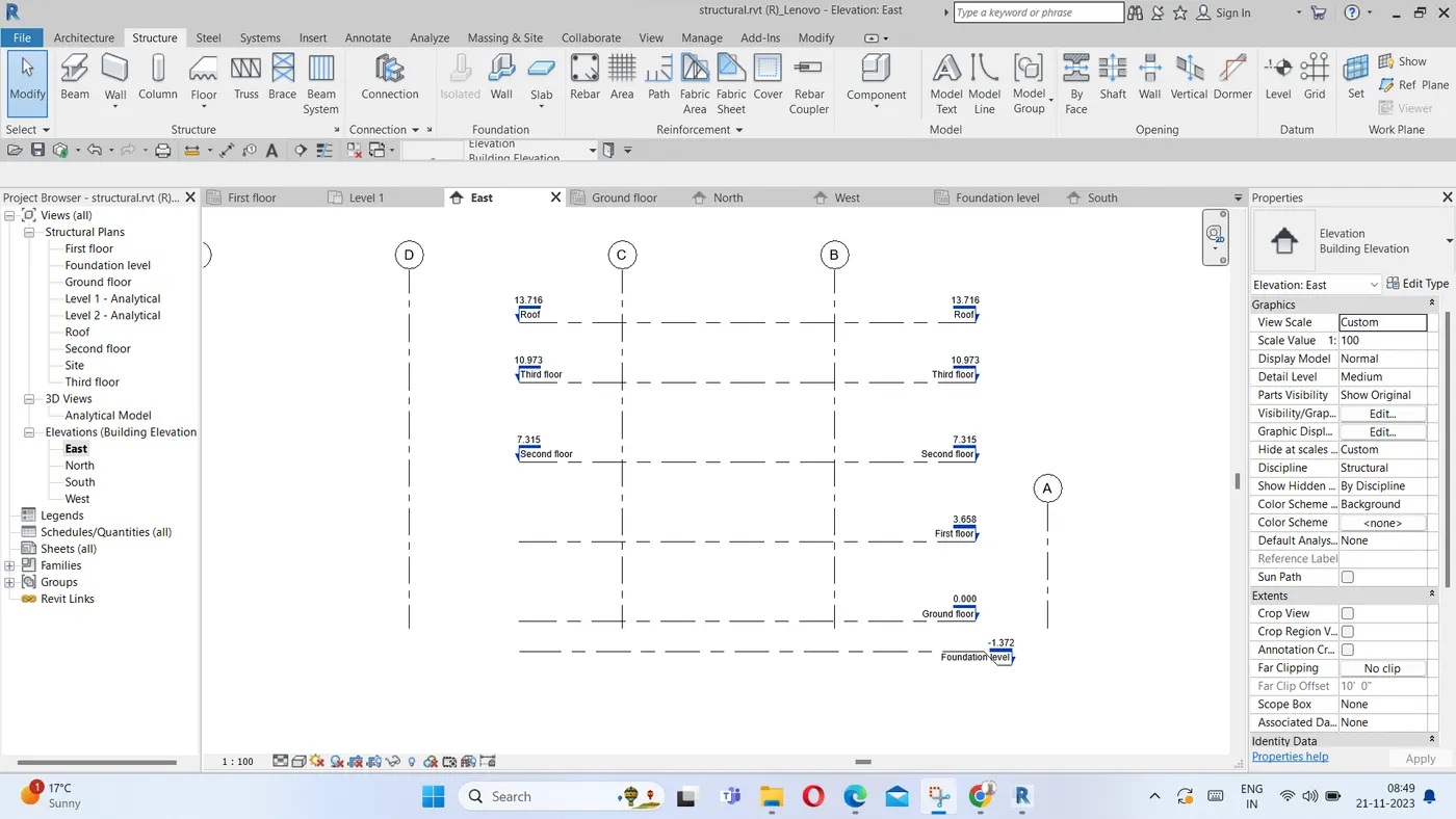
Levels are created using level option in Structural tab and their names are assigned as below-
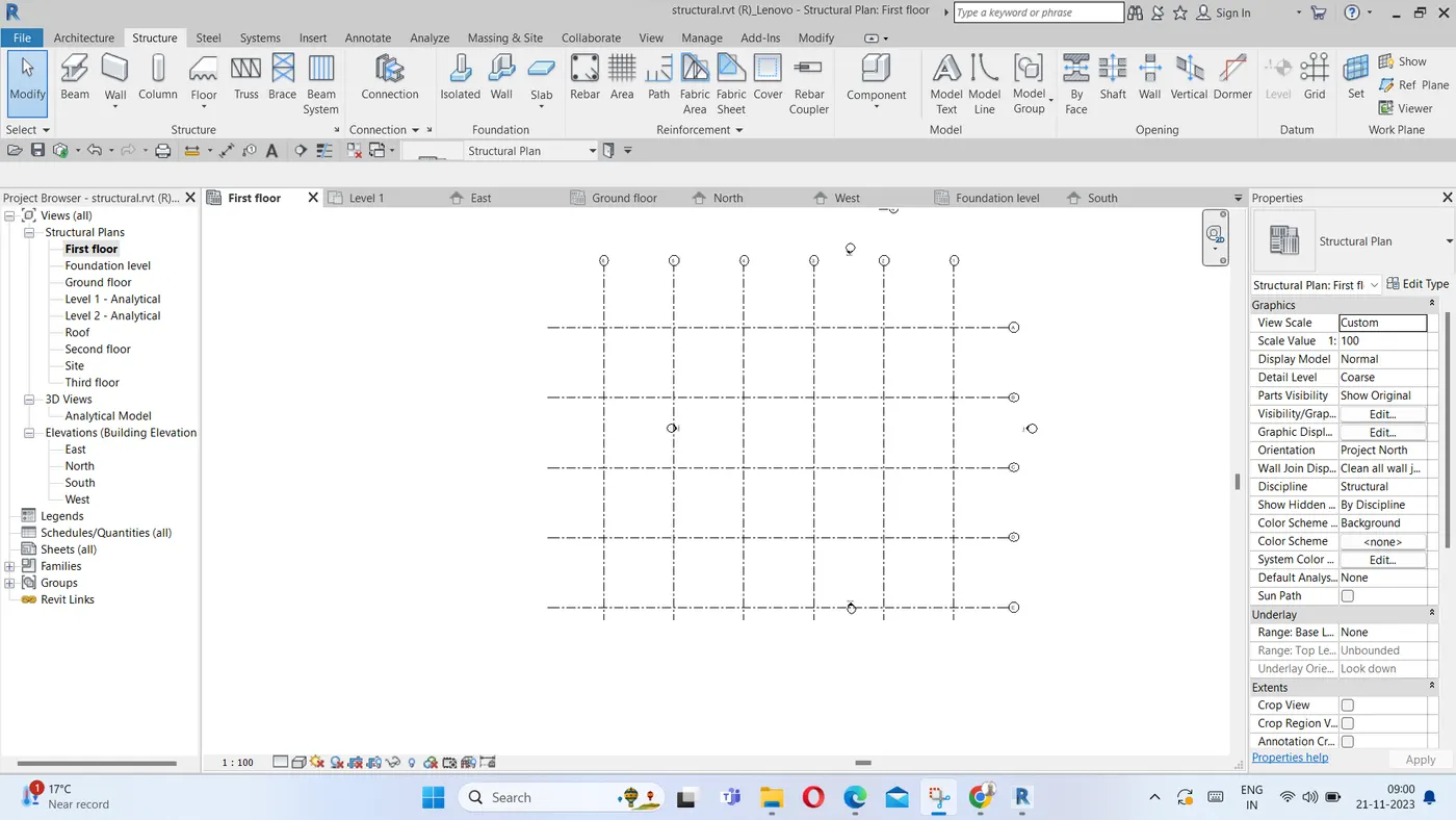
Horizontal and Vertical grids are created using Grid option of Structural tab as shown below-
Creating column :
- Go to the Architectural tab
- Click wall dropdown
- Click on wall architectural
- Choose line option to draw boundary
- Create boundary
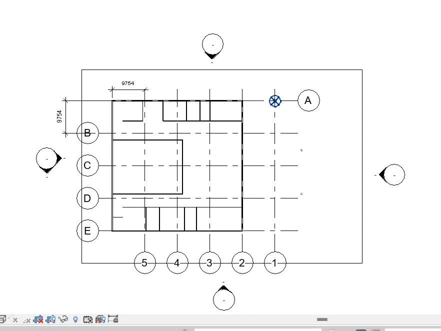
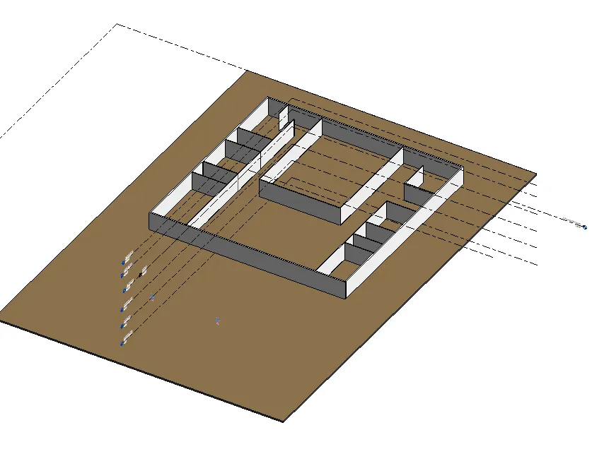
Go to file ,click new and click Archetectural tab -
Using Archetectural tab and level option , levels as per requirement are created from Elevation view-
Creating Grass around model :
- Go to massing and site tab
- Click on topo surface
- Click points around model then click finish to create earth surface as shown below-
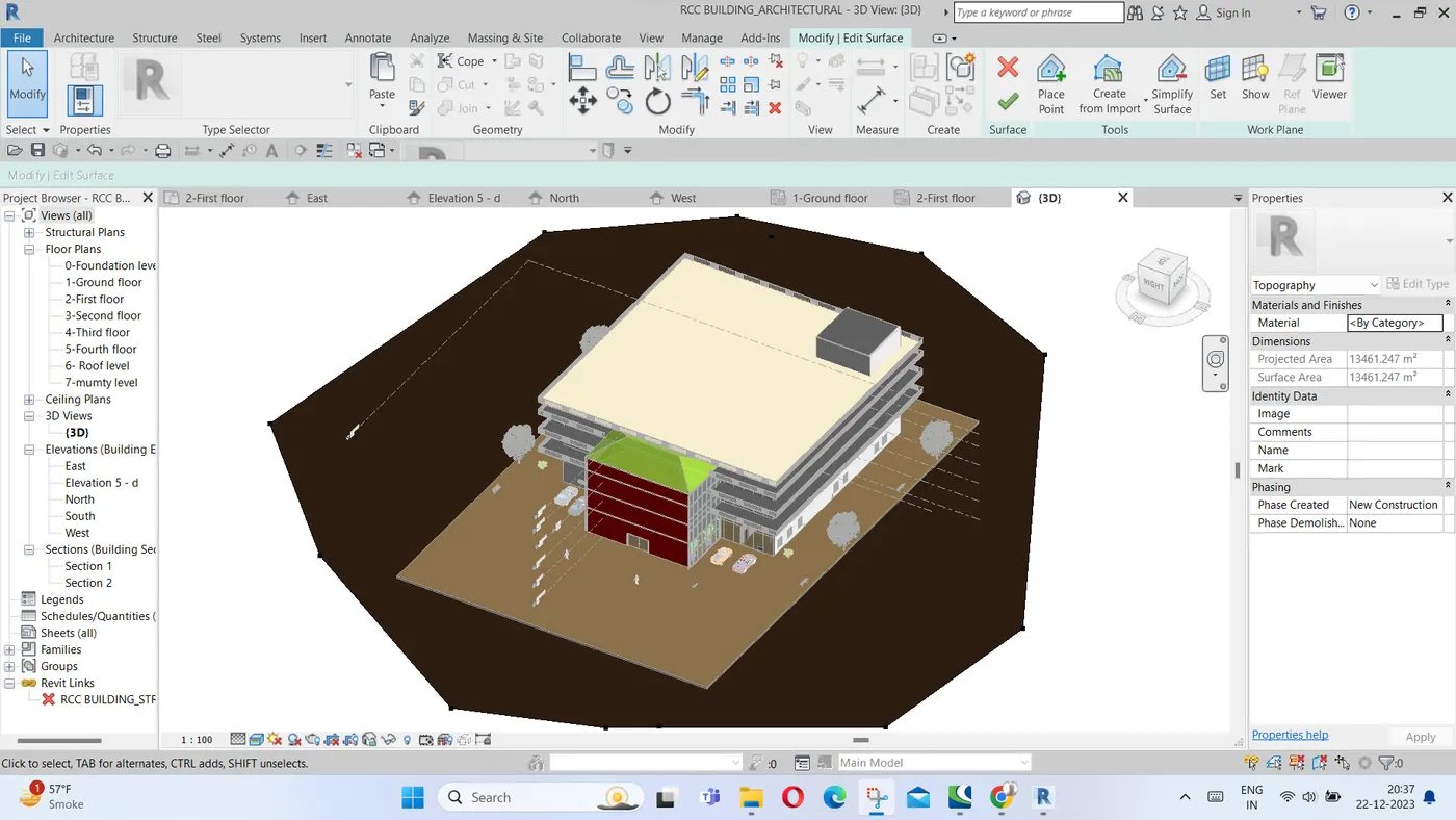
- Select topo surface which has already been created
- Go to Edit surface
- Click on category of material in property panel
- Create new material, default material is created
- Click on new material created and Rename as grass
- Go to appearence
- Go to image
- Select grass from saved location and double click on it then click OK. Grass is created as below-
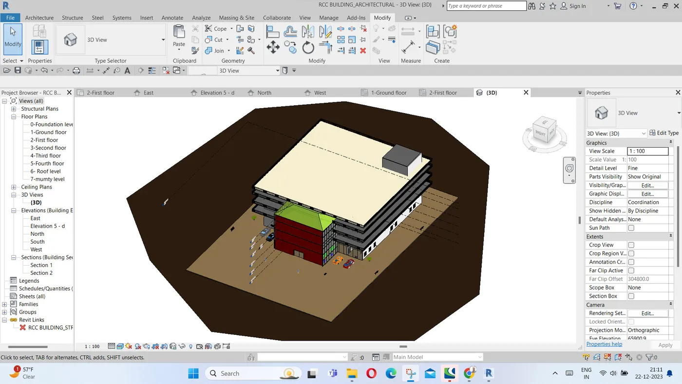
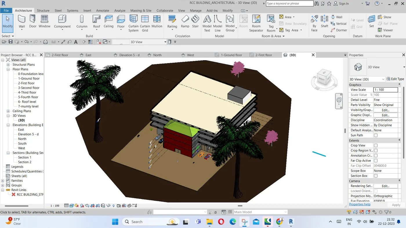
Creating trees :
- Go to Archetectural tab
- Drop down component
- Click on place component
- Click Load family
- Select tree component from the folder where it is saved
- Click at points where tree or plant is to be placed as shown below-
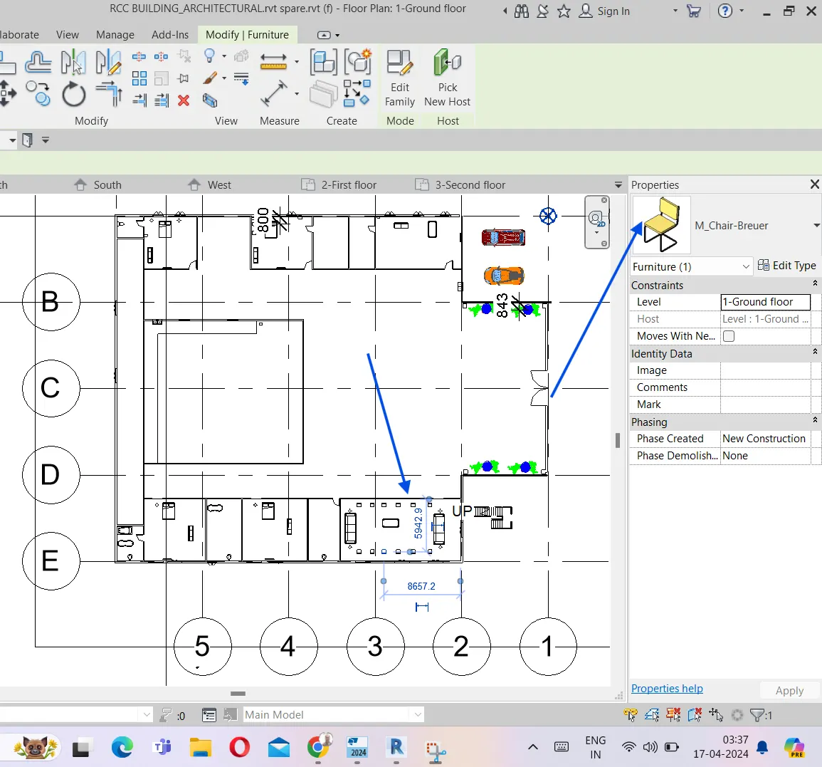
Creating Chairs :
- Select Archetectural Tab
- Go to the Component Tab
- Click on place a component
- Click on load family
- Cilck on Furnitue then click on seating and finally select Chair
- Place Chairs at desired locations marked with arrows as shown below :
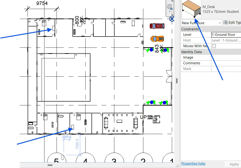
Creating Desk :
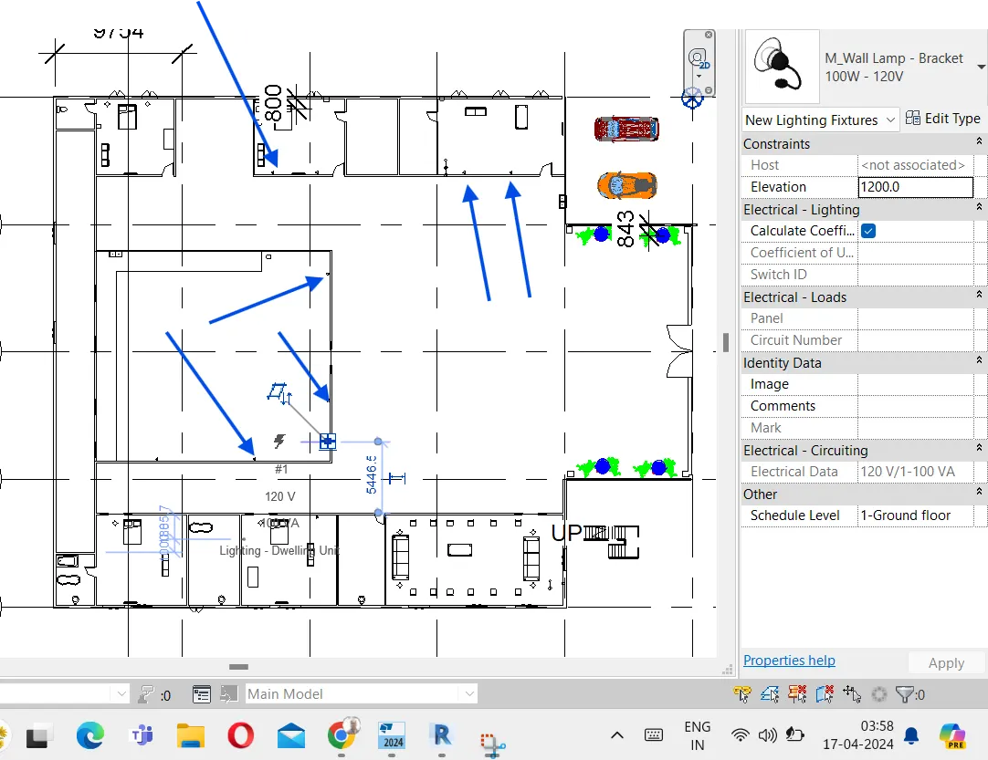
Creating wall lamp :
Creating Plumbing fixtures :
- Select Archetectural Tab
- Go to the Component Tab
- Click on place a component
- Click on load family
- click on progamme date folder in C drive
- Click on Autodesk folder
- Click on Revit 2019 folder
- Click on Library folder
- Click on India folder
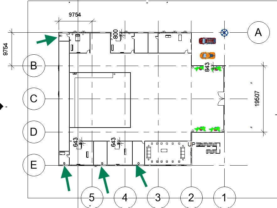
- Click on plumbing folder
- Click on WC and place at desired locations marked with arrows as shown below :
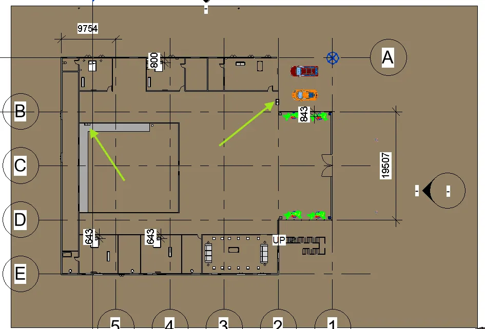
Kitchen sink marked with Yellow arrow as shown below :
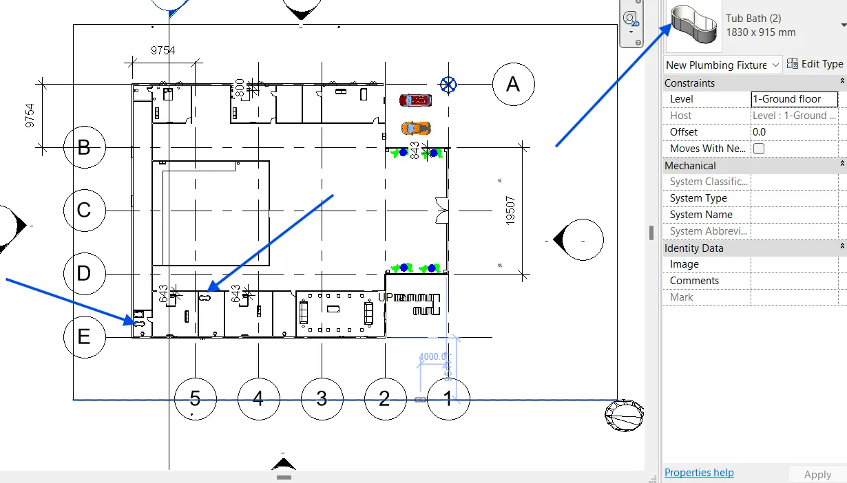
Bath tub marked with blue arrow as shown below :
Modelling stair case :
- Go to the floor plan
- Select Architectural Tab
- Click on stair
- Click on Run
- From property select base level as ground floor and top level as Second floor as marked below with arrow.
- Click at one point and model the staie in one direction then approximately break after three fourth of total numbers of steps are modelled then modle in opposit direction then click OK
- Stair case from ground level to the first floor level will be created.
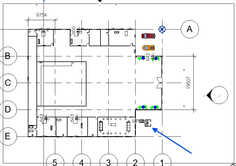
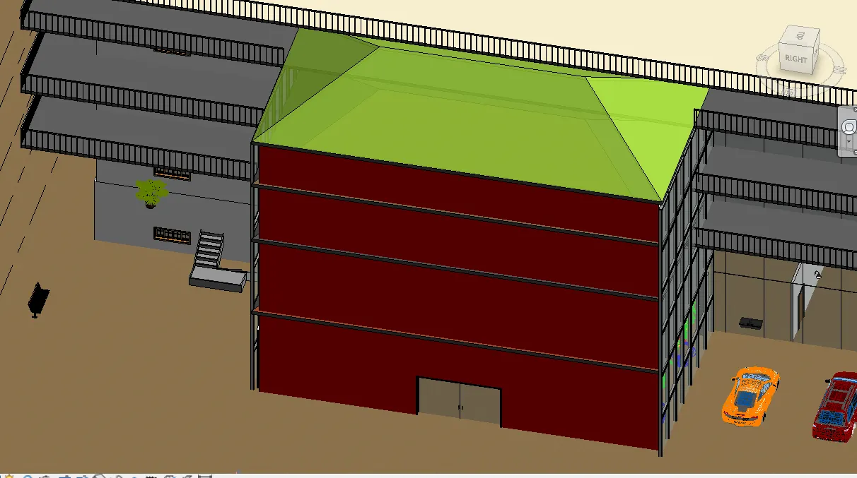
Staircase from First floor to Second floor is SHOWN BELOW :
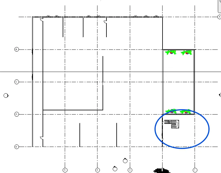
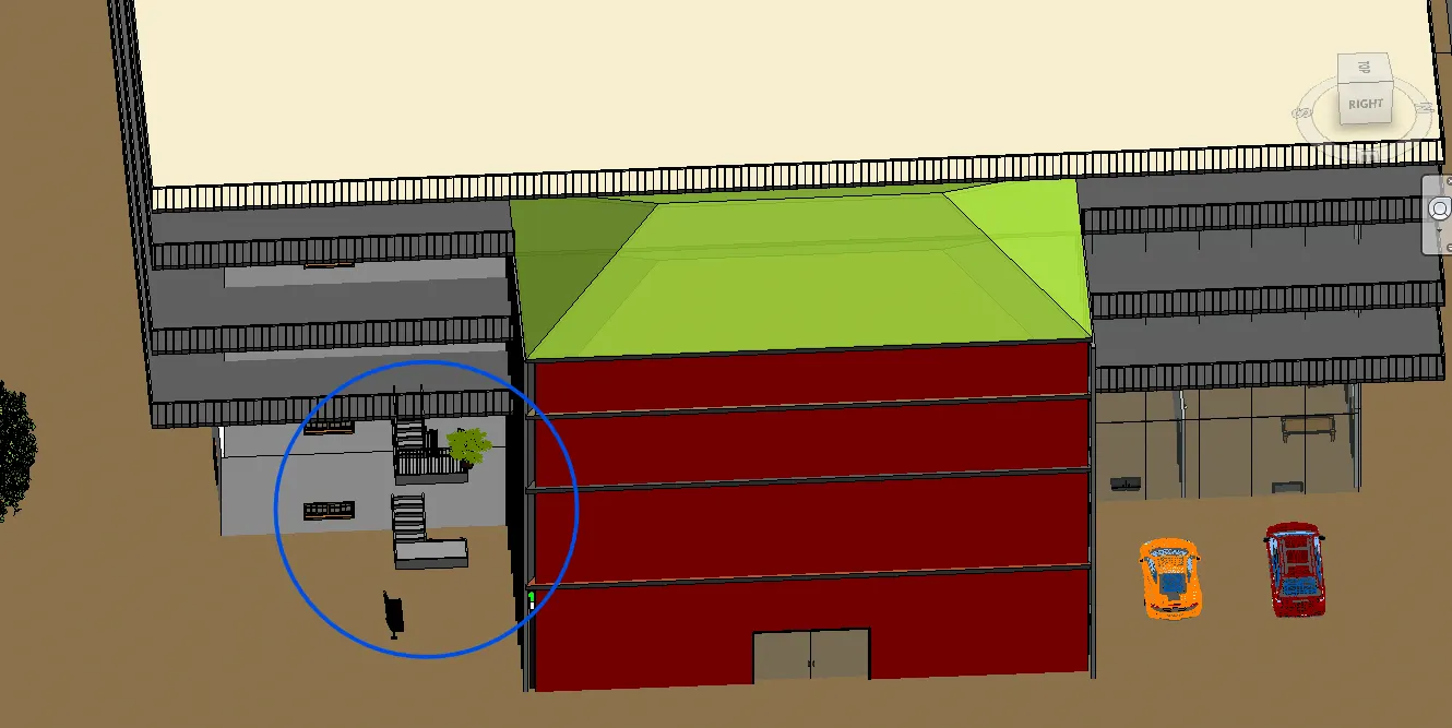
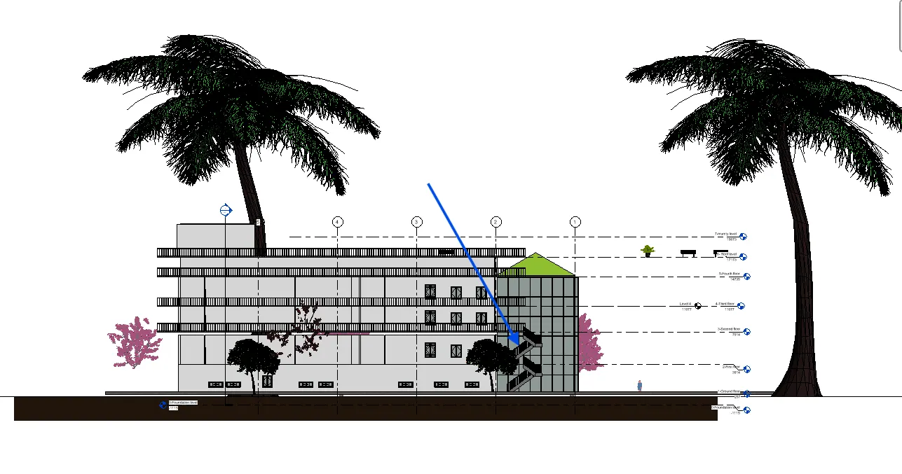
Elevation view :
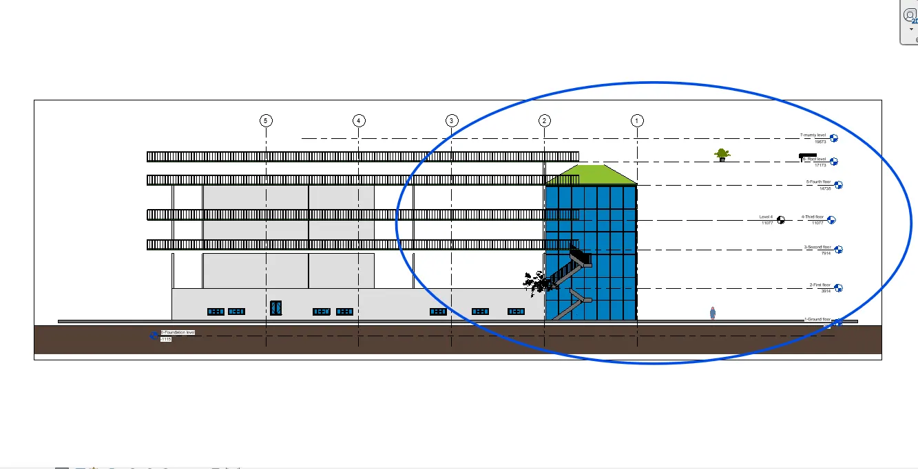
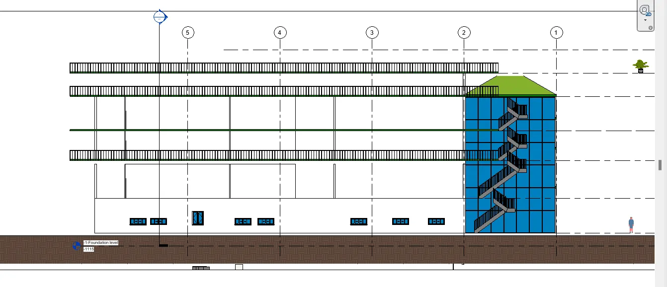
RESULT: Thus in architectural model including Wall Layout with appropriate material and finishing, Exterior façade with fancy finish, Interior partition walls to size rooms, Components such as Desk, Chair, Lighting, Plumbing fixtures, stairs Elevators, at-least one side of the building with curtain walls and glass panels, interior and exterior lighting fixtures, topographic components from outside ( Trees, Parking, Plants) has been created. RVT file is atteched
--------------------------xxxxxxxxxxxxxxxxxxxxx------------------xxxxxxxxxxxxxxx----------------------
5) Provide a set of drawings in an architectural and structural model to list the following details with categories and appropriate sheet templates included
a. Floor Plans with Annotations
b. Elevations
c. Sections
Ans :4 : Aim & Introduction : Floor plans with annotation , Elevation and Sections are required to be provided in appropriate sheet templates.
Procedure in deatil :
Ans :4 : Aim & Introduction : Floor plans with annotation , Elevation and Sections are required to be provided in appropriate sheet templates.
Procedure in deatil :
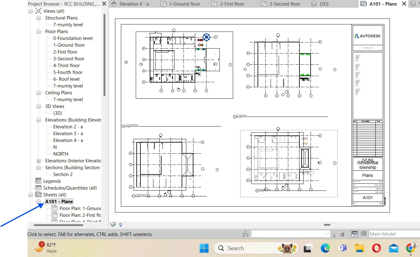
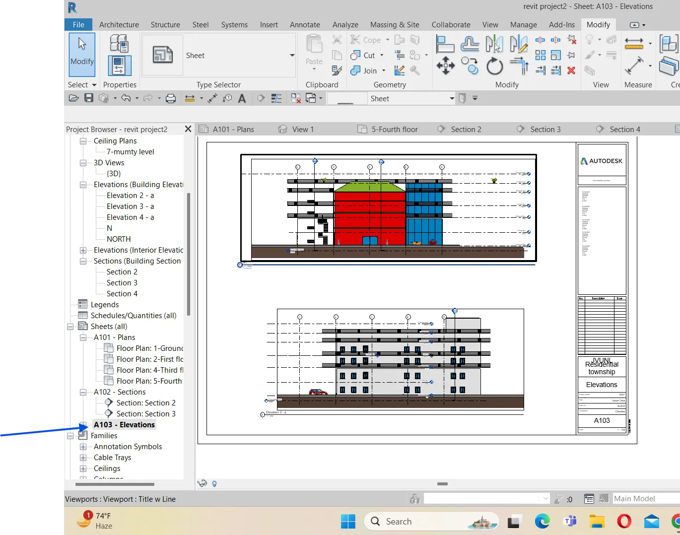
- Go to the view
- Choose the template ( Choose the size of paper out of various standard size , A0 , A1 , A2 , A3 & A4 )
- Drag and drop the views from project browser into sheet as shown below :
Plans :
Elevations :
Sections :
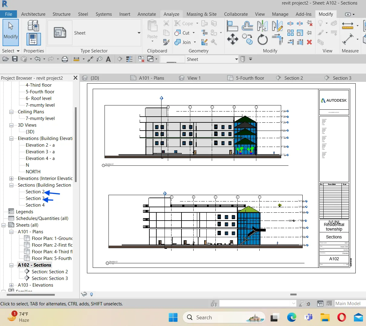
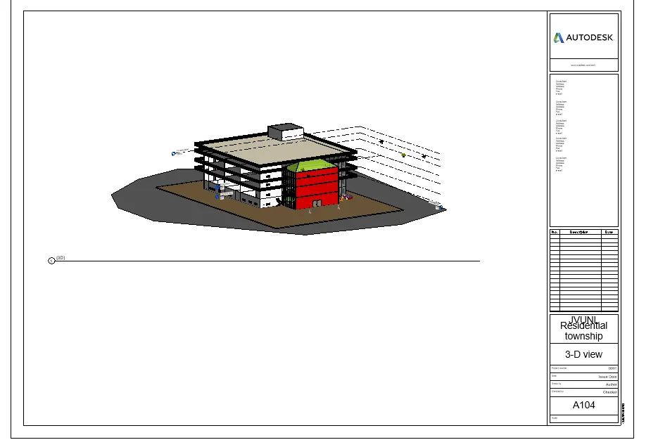
Result : Thus as required , sheets have been created and plan , sections and Elevations views have been shown above.
----------------------------xxxxxxxxxxxxxxxxxxxxxxxxxxxxxx----------------------------------
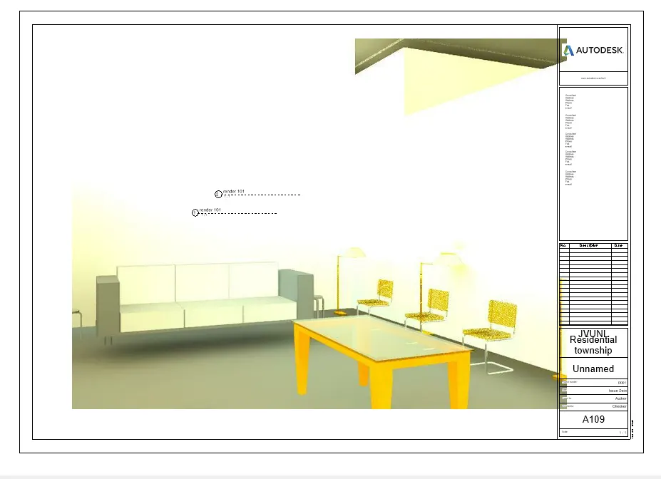
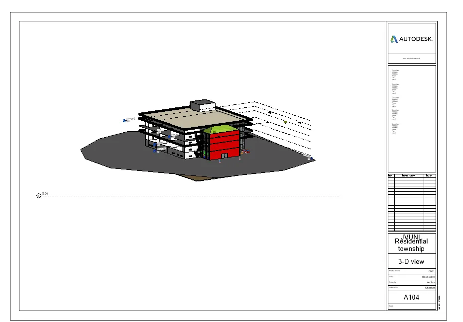
6) Using the Rendering settings, Render images of the 3D model produced and include the rendered images to the drawing sheets
a. Rendering from interior rooms
b. Rendering from out showing topographic features
c. Rendering through structural framing
Aim & Introduction : Rendering images of 3-D model to be produced on sheets.
Procedure in detail :
Rendering from Out showing topographical features :
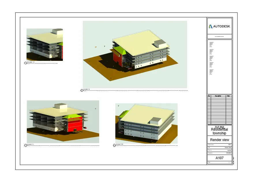
Render view with internal artificial light only :
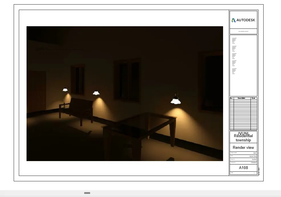
Render view with internal sun light :
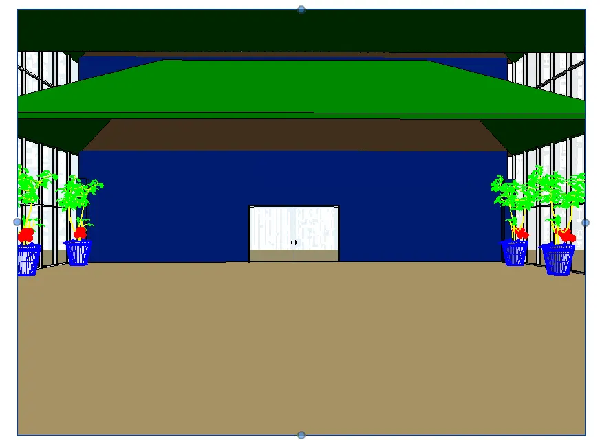
Rendering view with only sunlight :
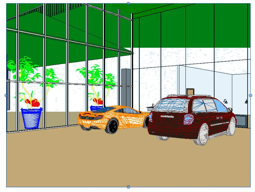
Rendering view with external artificial light only :
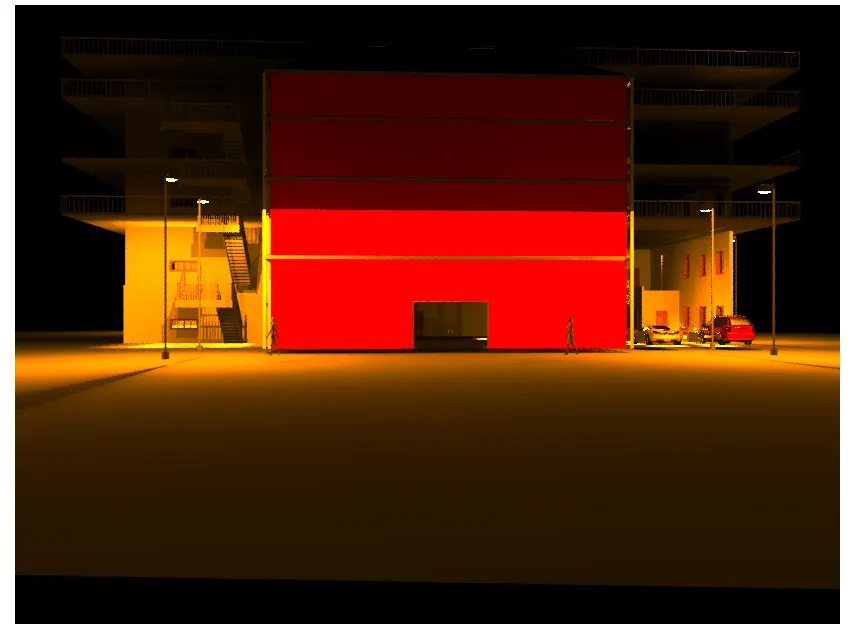
Result : Render images of 3 -D models are generated as above. Sheets of rendered images have also been created as required.
-------------------xxxxxxxxxxxxxxxxxx-----------xxxxxxxx------------------------------------------