Creating Architectural and Structural model with 3D rendering using REVIT
1) AIM:
To select the type of structure you want to build from one of the three below:
a. Multi-Unit Residential Apartment
b. Office Buildings
c. School
The type of structure I want to model in Revit is 'b. Office Buildings'
2) AIM:
To assume reasonable assumptions for geographic and location details for your project modeling. Based on assumptions and type of structure selected identify the modeling requirements from NBC
Assumptions made:
a. Height Limitations :
The height of the building shall not exceed 15m.
In my case, the height of the building is chosen as 9m
b. Area Limitations :As per NBC Clause 2.3.1 The Minimum Plot Size with ground coverage not exceeding 75 % , shall not be less than 40sqm in small and medium town and not less than 30sqm in metropolitan area.
In my case, the plot size is 600sq.m
c. Room sizing: As per NBC 2005, Clause C -3.3, Total area of all rooms shall not less than 15.5 sqm
- The area occupied Floor Area Ratio, FAR= total covered area of all floors /total plot area
- Room size is standard as per NBC.
In my case, the total area of all rooms is 19.38*10.65 = 206.39 sq.m
The plot size is say, 30 * 20 = 600 sq.m
FAR is 2.9 which is as per NBC
d. Wall height : As per NBC 2005 Clause F -3.4
In my model, the height of the wall is 3m
e) Thickness based on fire and life safety:
The assumed thickness of brick wall in my model is more than 230mm which is safe
3) AIM:
Using the structural model, include the following components based on the type of structure selected
a. Foundation – Isolated / Wall/Matt Foundation
b. Columns
c. Beams Connected to Columns
d. Roof Framing/ Truss
e. Floor / Decks
f. Floor Openings for Elevators and Stairs
Procedure:
Create a new model in Structural template
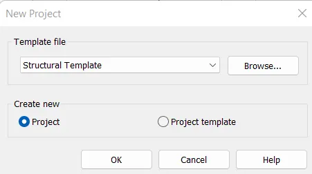
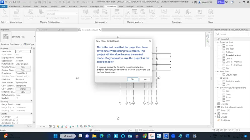
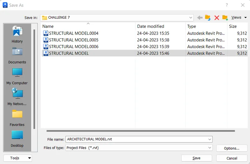
Save the model as ' Structural Model'
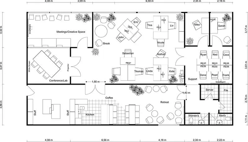
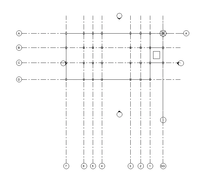
The plan of the office building is as shown below
Note that all the dimensions are in m. So type UN and change the length, distance units accordingly
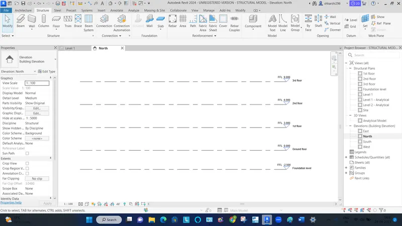
Before modelling the grids, let us model the levels using any of the elevations view
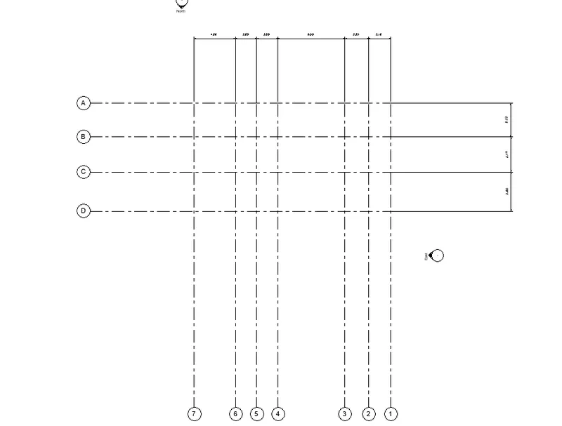
Now go to the foundation level to model the grids as in plan
Model the foundations at all grid intersections
Structure - Foundations - Edit type. Duplicate the foundation as per requirement
Click on All grids option, select all the grids and add the foundation
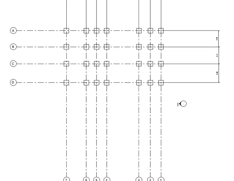
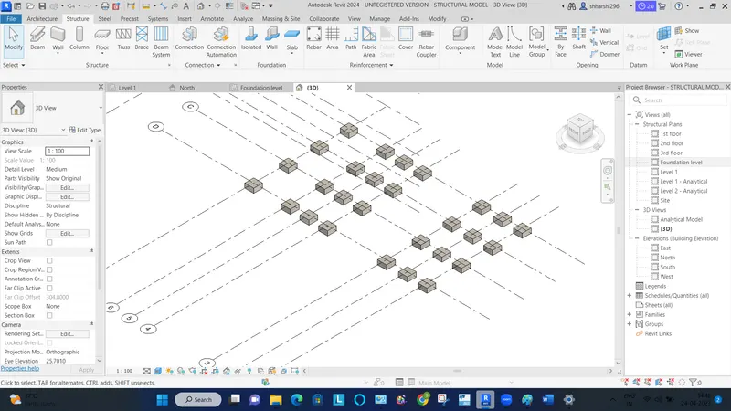
Now model the columns in Foundation level
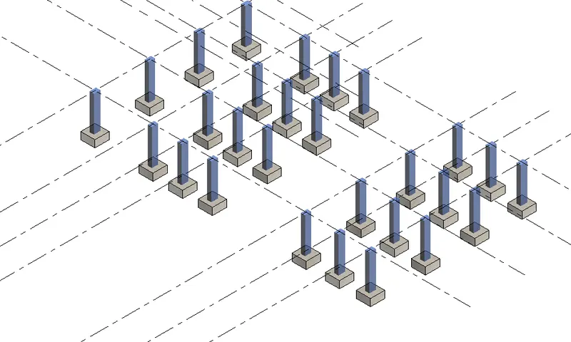
Similarly model the columns in the remaining levels too
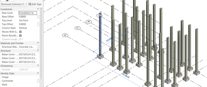
Model the beams. Structure- Beams- All grids
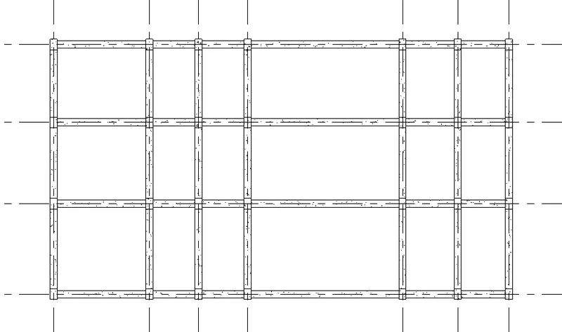
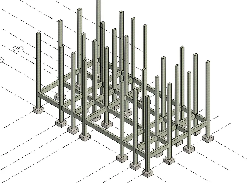
Now copy all the beams in the GF and paste it to other levels

Model the floors at all levels
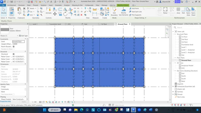
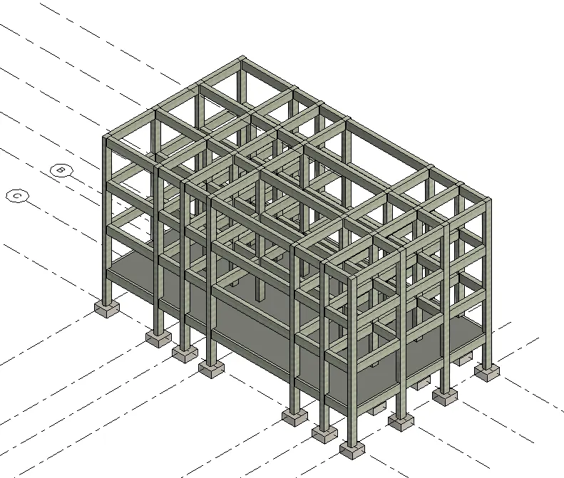
Copy the floor to the other levels
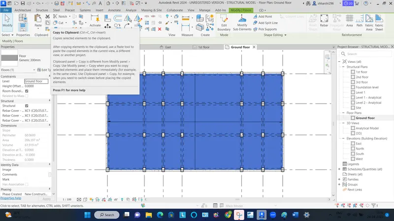
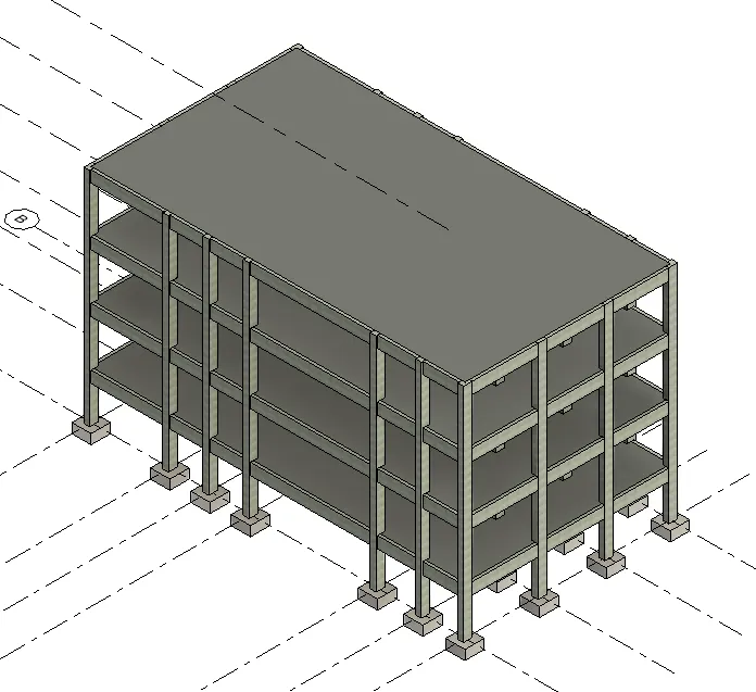
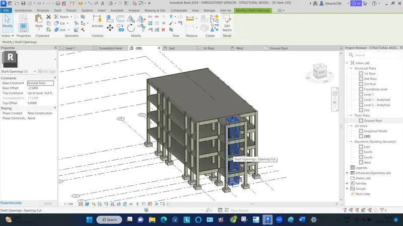
Create grids,foundation, columns, beams and floors for creating openings for staircase
Go to GF and Structure - Shafts to create a shaft opening from GF to 3rd floor
Later once the architects model the staircase, this shaft can be edited again
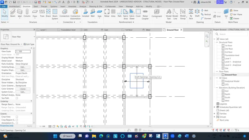
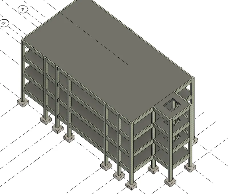
Now set the base point of the grid as 0,0
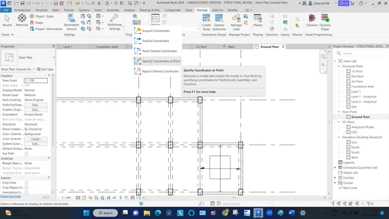
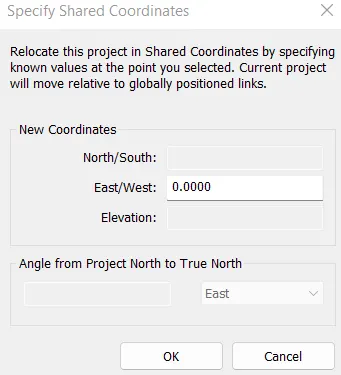
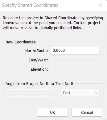
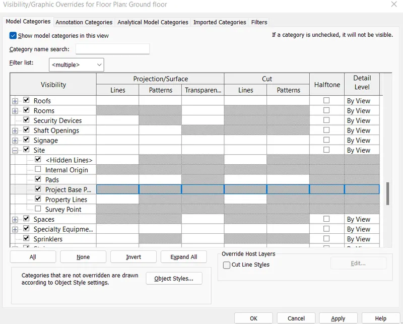
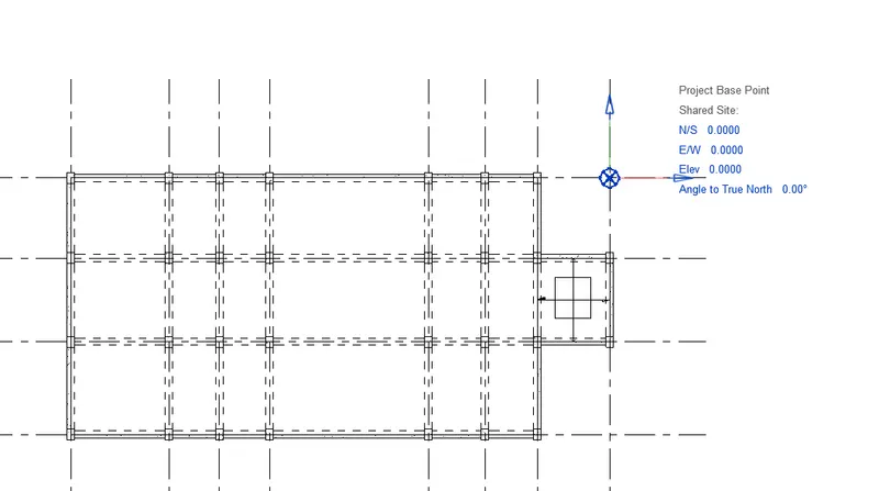
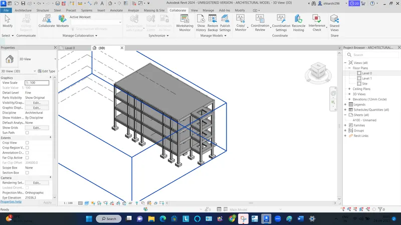
Manage - Collaborate to make the model as a Central model
4) AIM:
Using the architectural model, include the following components based on the type of structure selected
a. Wall Layout with appropriate material and finishing
b. Exterior façade with fancy finish
c. Interior partition walls to size rooms
d. Components to add details to a room ( Desk, Chair, Lighting, Plumbing fixtures)
e. Add components such as stairs Elevators
f. Have at-least one side of the building with curtain walls and glass panels
g. Include interior and exterior lighting fixtures
h. Place proper topographic components from outside ( Trees, Parking, Plants) to add details to the model
Procedure:
Create a new project in the Architectural template
Save it as Architectural model
Set the project base point
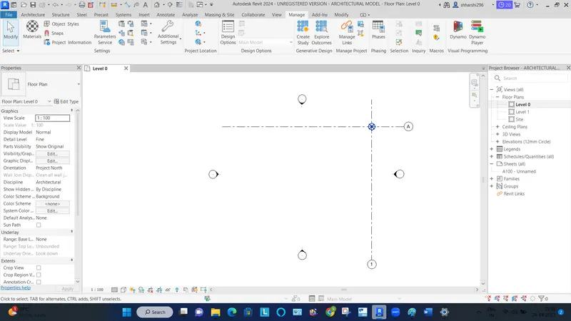
Insert - Link. And insert the Structural model into the architectural model
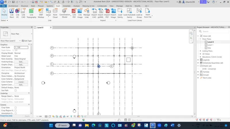
Specify the project base point to 0,0 and move it accordingly
Collaborate - Copy|Monitor
Select the link
Copy|Monitor - Multiple . Select the grids of the structural model and click Finish twice
Go to Views - Plan views -Ground floor,1st,2nd and 3rd floors
Draw the walls on the exterior sides
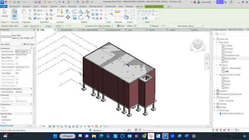
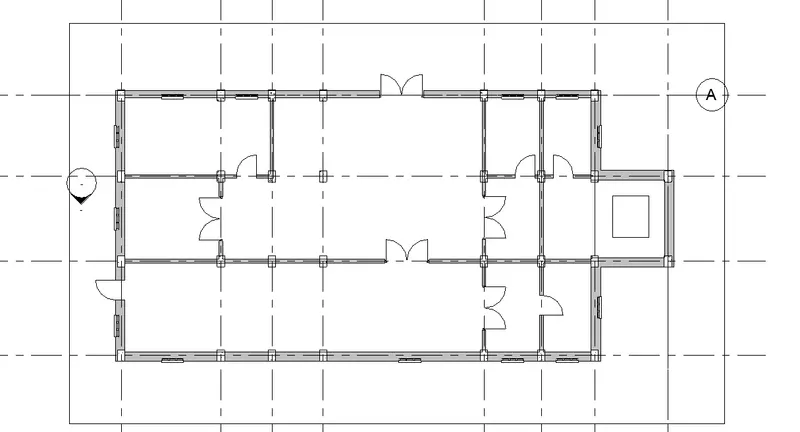
Now draw the partition walls and Add doors and window openings
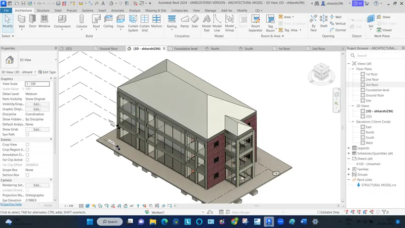
Now add roof to the ceiling
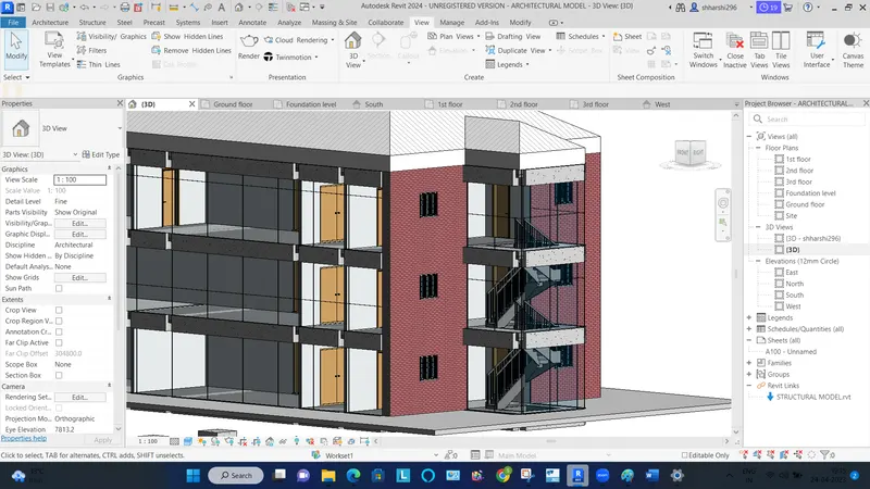
Add staircase in the shaft area
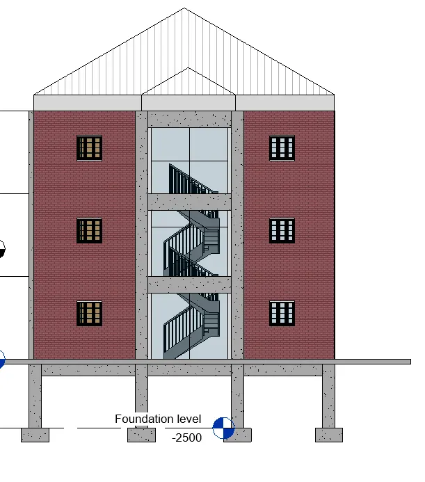
Place furnitures in each level
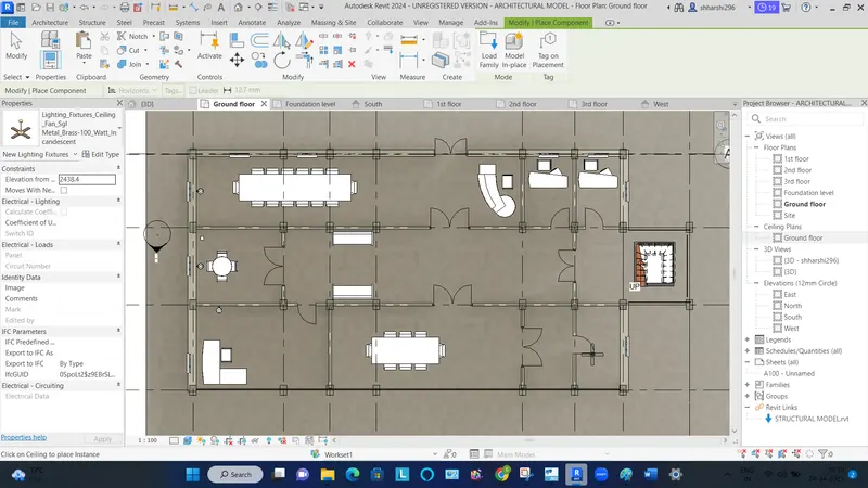
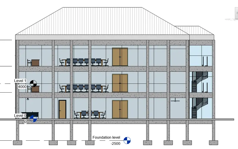
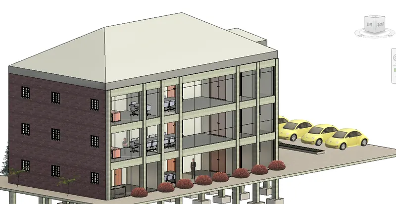
Go to Massing & Site to add the toposolid
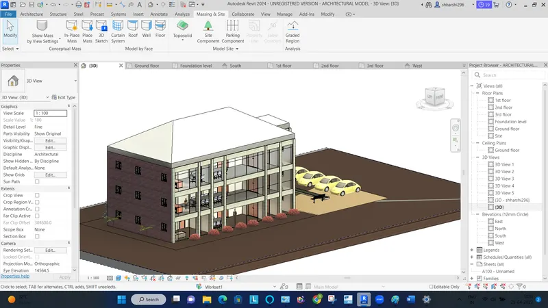
5) AIM:
To Provide a set of drawings in an architectural and structural model to list the following details with categories and appropriate sheet templates included
a. Floor Plans with Annotations
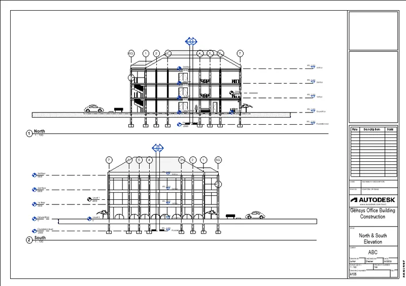
b. Elevations
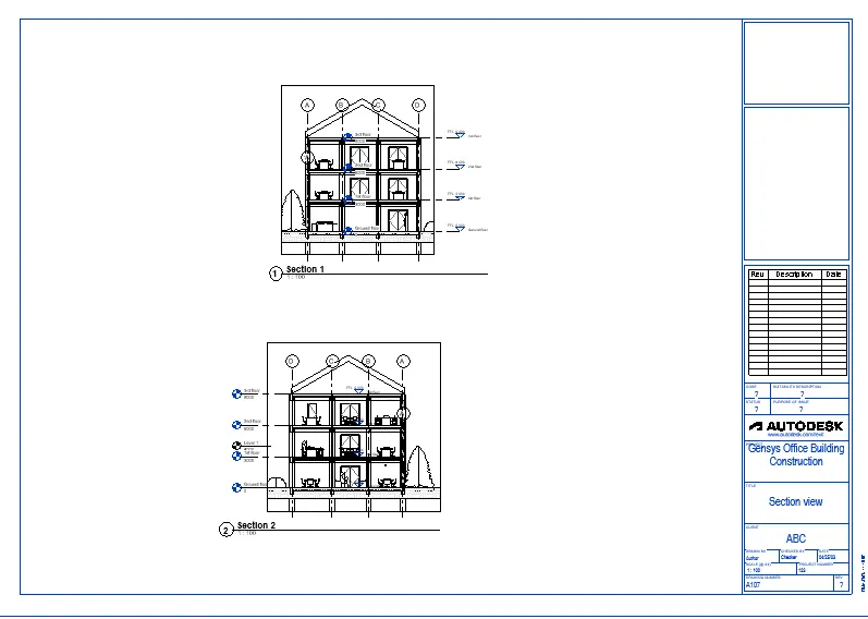
c. Sections
Procedure:
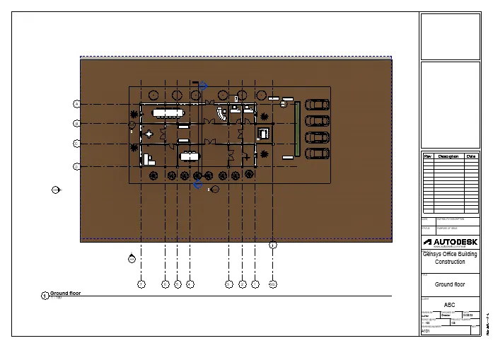
Manage - Project Information to edit the details in sheet
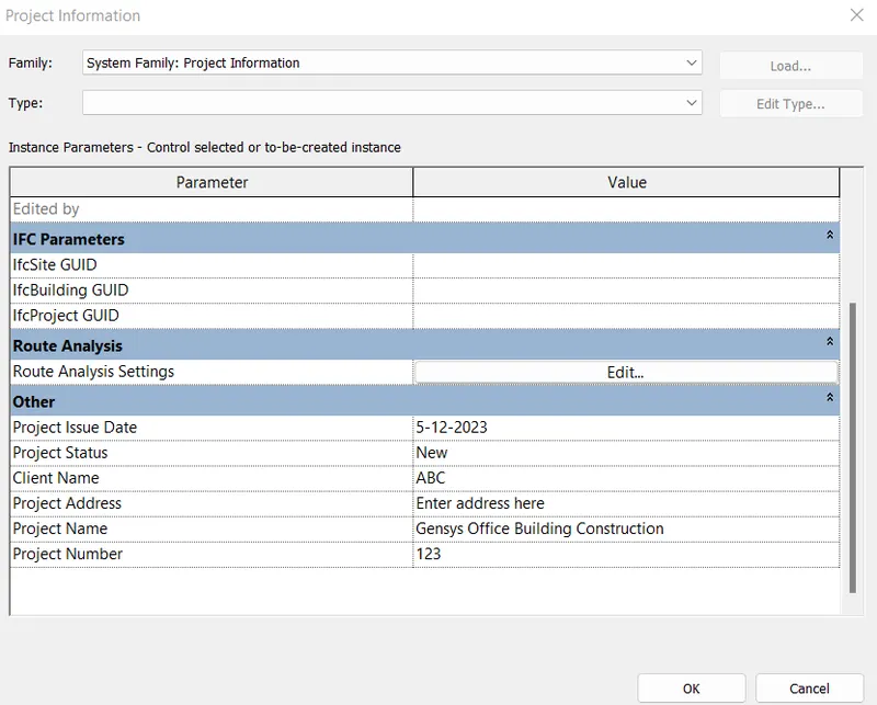
Go to View - Sheet
Drag and drop views to the sheets
6) AIM:
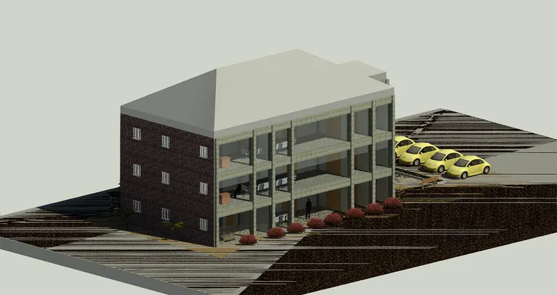
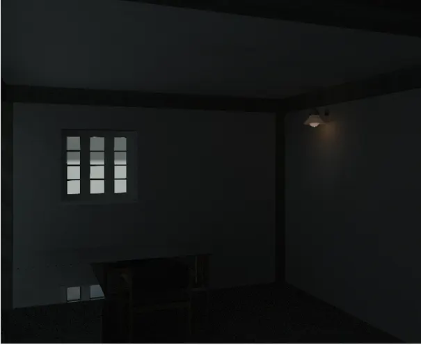
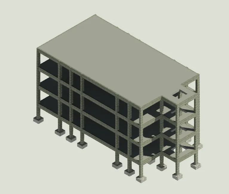
Using the Rendering settings, Render images of the 3D model produced and include the rendered images to the drawing sheets
a. Rendering from interior rooms
b. Rendering from out showing topographic features
c. Rendering through structural framing
Procedure:
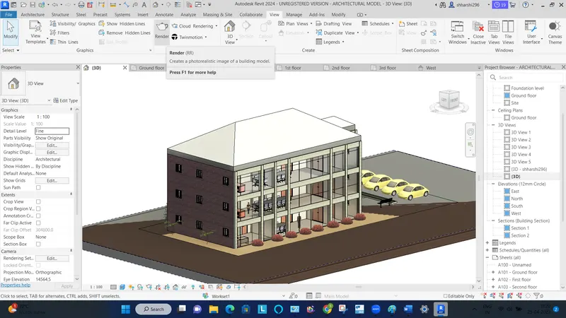
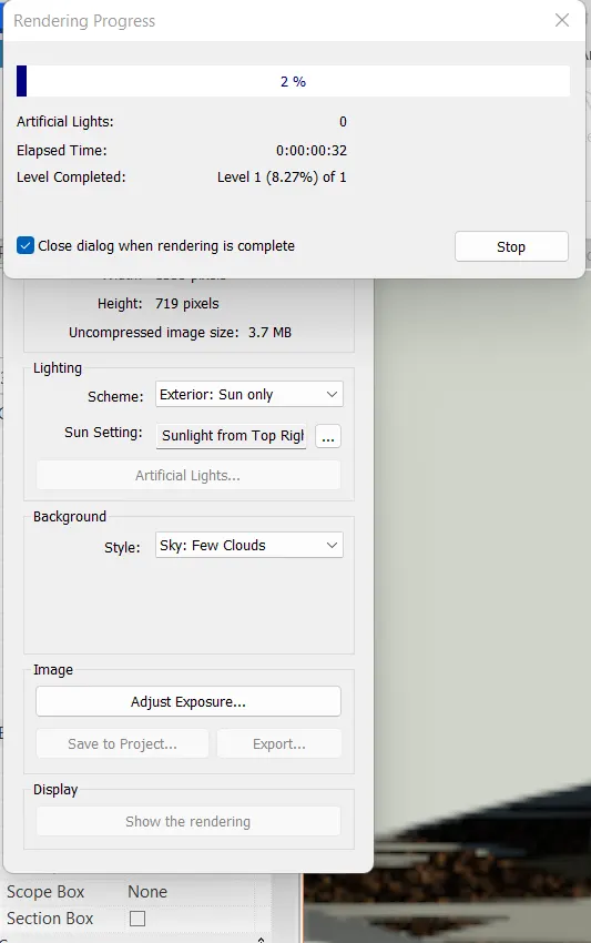
Go to any 3D view
View- Render
7) AIM:
To Print the set of drawing sheets created and submit the drawings from the architecture and structure model
Procedure:
Go to any sheet and press Ctrl + P.
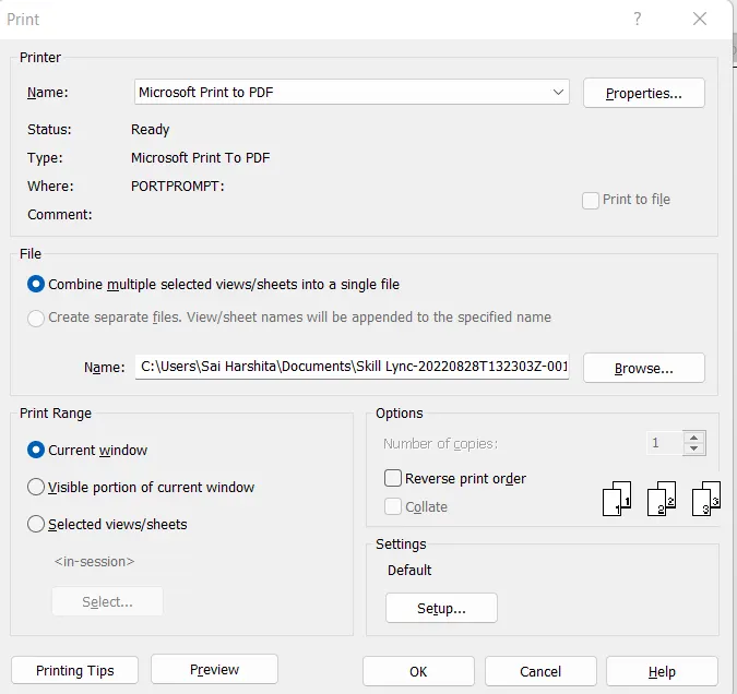
We can then save the pdf in any desired location