Creating Architectural and Structural model with 3D rendering using REVIT
1) Select the type of structure you want to build from one of the three below:
a. Multi-Unit Residential Apartment
b. Office Buildings
c. School
From the above the options of choos type of structure to build a building,
I need to pick a School Building.
2) Assume reasonable assumptions for geographic and location details for your project modeling. Based on assumptions and type of structure selected identify the modeling requirements from NBC?
The geographical and location details of my project are :
1. As mentioned my building comes under School category and it can be situated in the center of the city.
2. My project is located near the highway.
3. The road width in front of my building is 18000mm
4. The height, area and safety measures will follow the rules and regulations of NBC.
5. The height of my project is 18000mm and the road width is 18000mm
6. So my building height is 18m and the road width is 18m, the height of the building should not exceed 1.5 times the width of the road width.
7. In this case the building height is not exceeding so it is suitable for construction.
8.The minimum height for habitable rooms is 2.75 m as per the NBC 2016.
3) Using the structural model, include the following components based on the type of structure selected
a. Foundation – Isolated / Wall/Matt Foundation
b. Columns
c. Beams Connected to Columns
d. Roof Framing/ Truss
e. Floor / Decks
f. Floor Openings for Elevators and Stairs
AIM:
- To Using the Structural Model, include the following component based on the type of Structural selected in Foundation, Columns, beams, Roof, Floor, Stair and Elevators.
PROCEDURE:
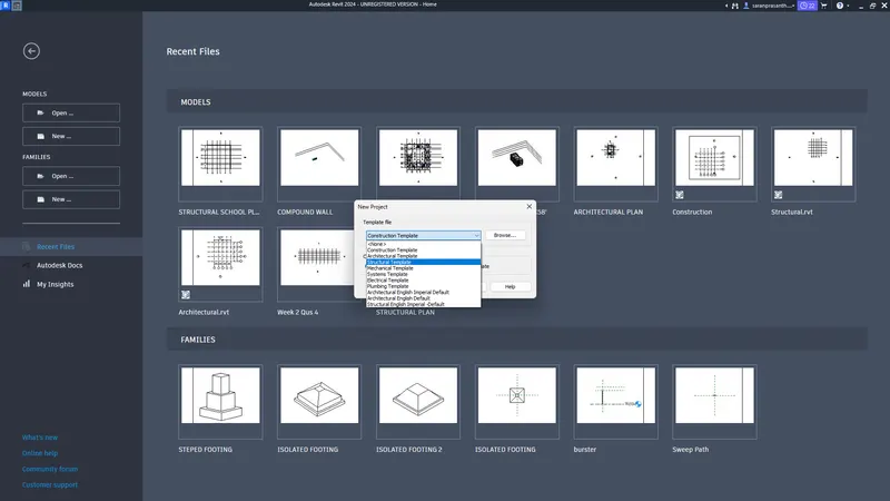
STEP1: TO OPEN STRUCTURAL TEMPLATE:
- Open the Revit Software.
- Then the Create the Structural template in Models.
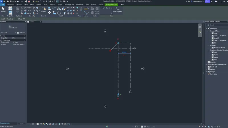
STEP 2: TO CREATE GRIDS AND LEVELS:
- Go to the Architectural tab and Datum colum there is to select the Grid.
- Draw the Grid line
- Same Process the levels also , Go to the Architectural tab and Datum colum there is to select the Levels.
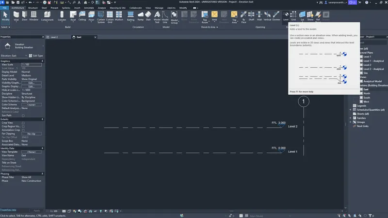
- Draw the Level line, give the offset is 3000mm ande six levels are created.
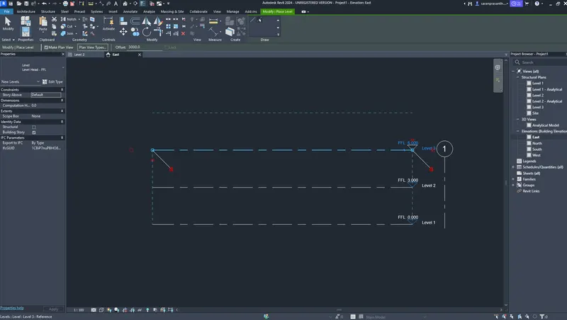
- The Final of grid and Levels is drawn in the below
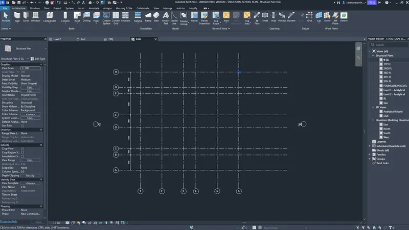
GRIDS:
- The Create the Grids in outer is center to center distance of the plot size(24000mmx24000mm)
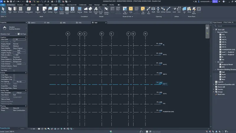
LEVELS:
- The create the Levels is height of building is 3000mm is drawn
- Below is Foundation level there the Ground level depth is 2500mm.
- Total building levels is 6, the name change is (foundation,0,1,2,3,4,5 and roof)
STEP 3: TO CREATE COORDINATE BASE POINT:
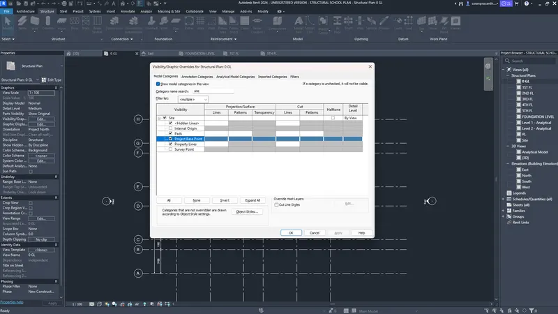
- Go to the Visibility Graphics and Shortcut is "VG"
- One Dialouge box are show.
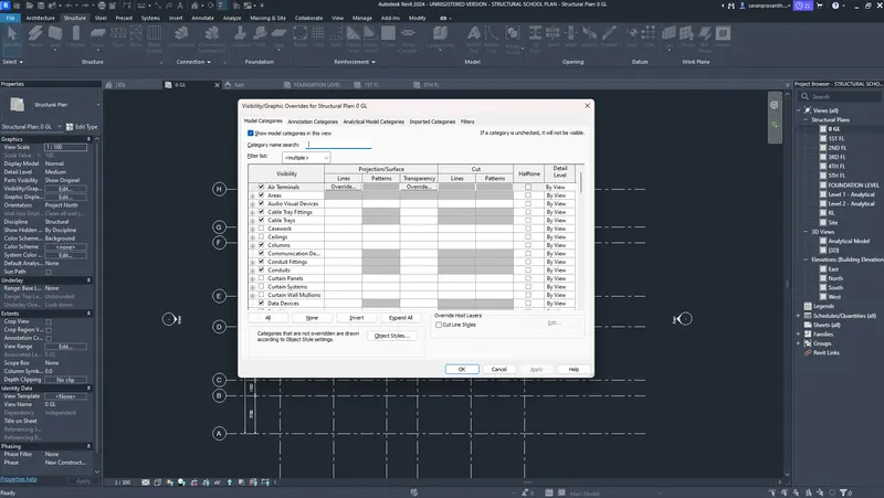
- That Visibility Dialouge Box there is Search tab to Search the "Site"
- Then the project Base Point to Select and tick, then Ok.
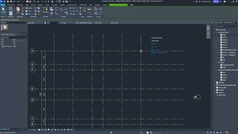
- The project Base Point is Created in the Structural Plan.
- That Symbol of Project Base Point to moved the Coordinate point created
- Go to the Manage Tab, then the Project Location column there is Coordinate to click.
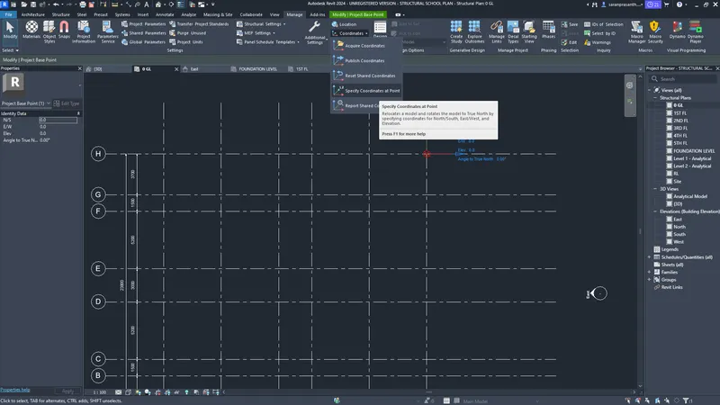
- Then Select the Specify Coordinate at Point to Click
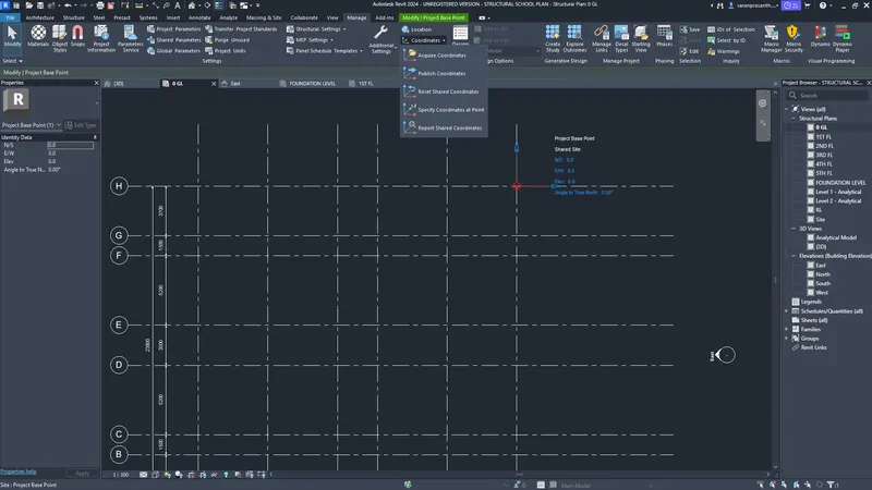
- Then Select the Specified Coordinate at a Point to Select Shown in Below
- After clicking one dialouge box will be open , Shown in Below
- The value is given 0
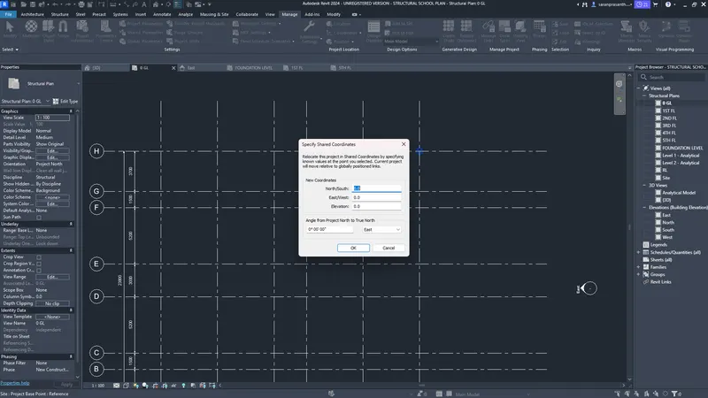
- After given the value , the Coordinate Point set at the Project Base Point
STEP 4: TO CREATE STRUCTURAL FOUNATION:
- Go to the Structural tab , then there is Foundation Column , If can select the any Foundation.
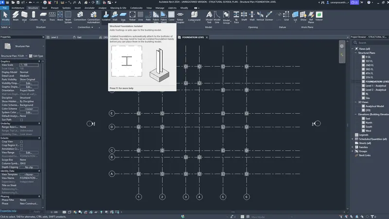
- I am using Steped Footing in the Structural Plan.
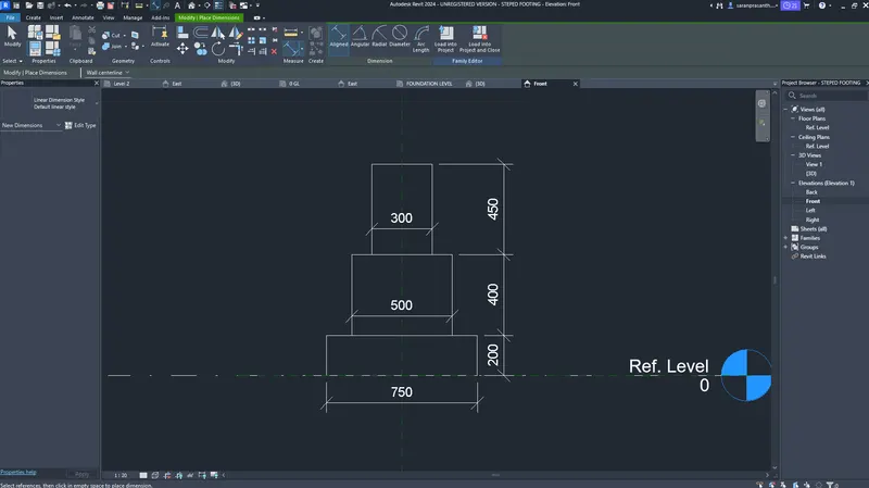
- The Steped footing is not there in the revit family, If you use the Family Template to create the Steped footing.
- The Steped footing size is shown in below.
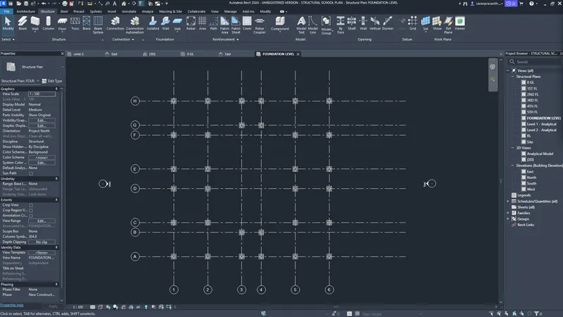
- Then the footing is placed above the grid line and where will Placed the placed in design the Structural Engineer.
- The Steped footing is placed the Foundation level shown in Below.
STEP 5 : TO CREATE THE STRUCTURAL COLUMN:
- Go to the Structural tab , then there is Stuctural Column , If can select the Column, the Shortcut is "CL"
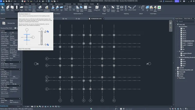
- The column is choosing the Concrete Rectangular Column .
- The Column size is change the go to the Proerties and Edit type , Dublicate the Family and Edit the Dimentions
- The Column size is 200mmx200mm
- Then the column are Placed the Foundation Level to Ground Level. Shown in Below
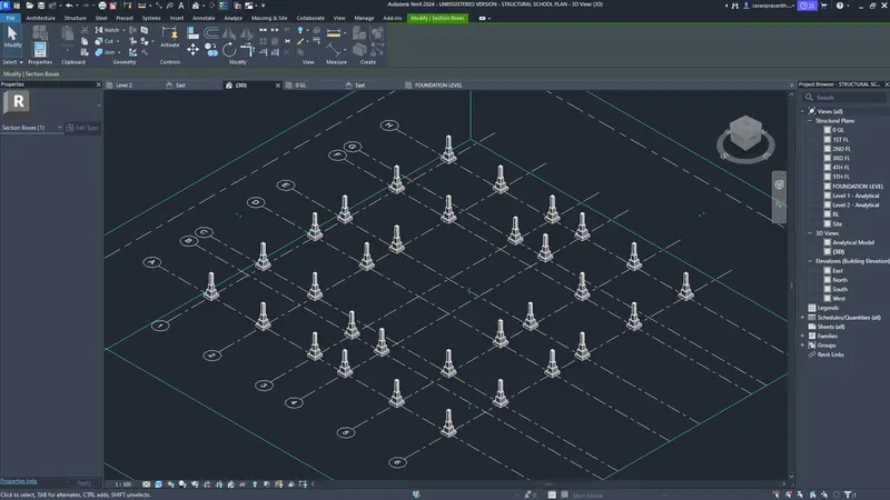
STEP 6: TO CREATE THE STRUCTURAL BEAM:
- Go to the Structural tab , then there is Stuctural Beam, If can select the Beam, the Shortcut is "BM"
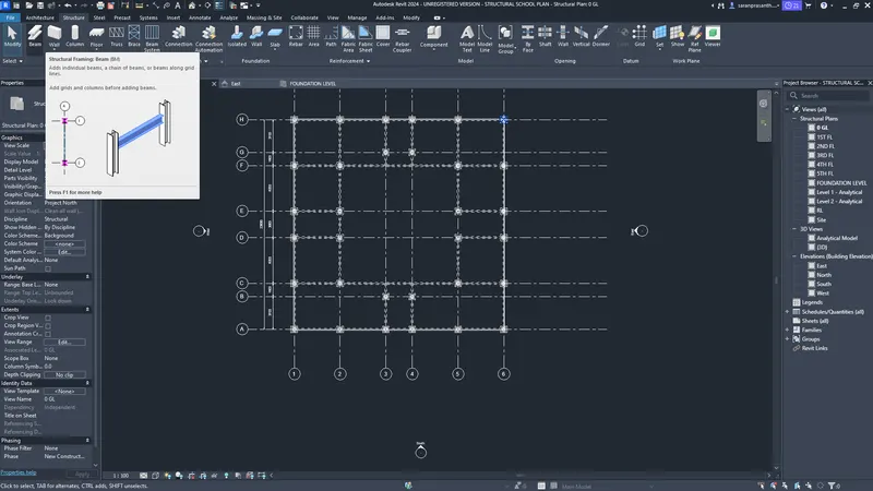
- The Beam is choosing the Concrete Rectangular Beam.
- The Beam size is change the go to the Proerties and Edit type , Dublicate the Family and Edit the Dimentions .
- The Beam size is 200mmx300mm.
- Then the Beam are Placed the at Column to Column Connection to manually create the Beam. Shown in Below.
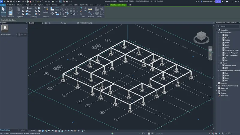
STEP 7: TO CREATE THE STRUCTURAL FLOOR:
- Go to the Structural tab , then there is Stuctural Floor, If can select the Floor, the Shortcut is "SB"
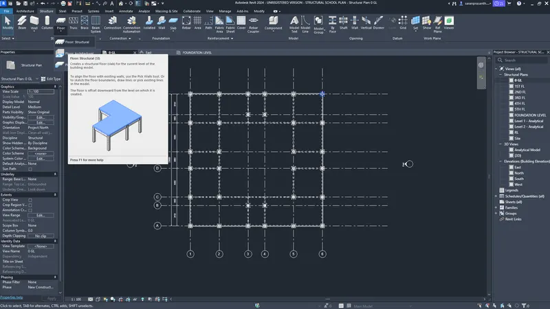
- The Floor is choosing the Floor slab.
- The Floor size is change the go to the Proerties and Edit type , Dublicate the Family and Edit the Dimentions .
- The Floor thickness is 150mm
- Then the Floor to create the manually. Shown in Below.
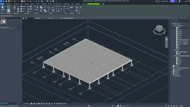
- Same Process to the all Level , So am simply copy the all element to Place the all levels.
STEP 8: TO COPY THE STRUCTURAL ELEMENT PLACED LEVELS:
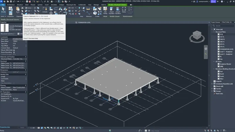
- Select the Structural Element , Ribbon is changeed the Modify Tab
- There is Copy Symbol to Click , Shown in Below.
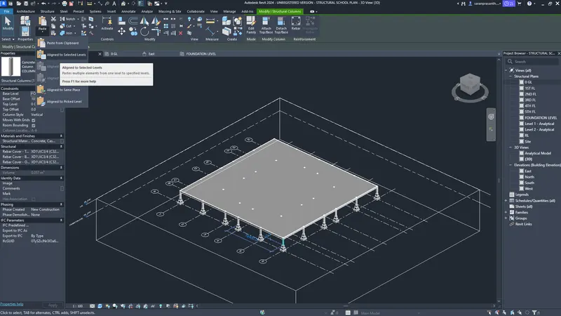
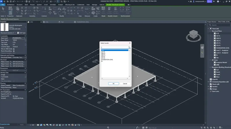
- Then the Paste symbol there to click that and select the Asigned to select levels. Shown in Below
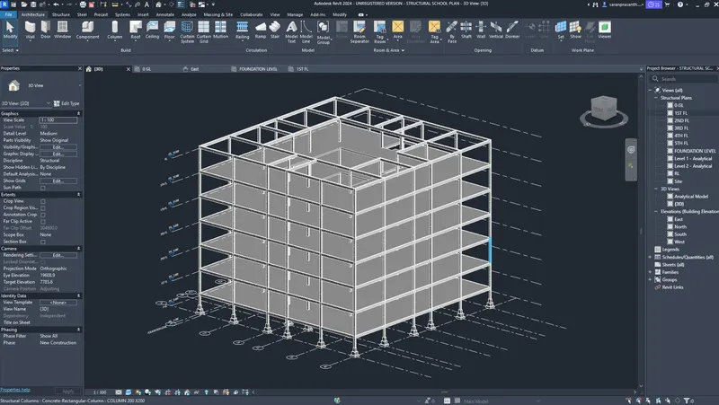
- Select the levels you paste the Structural element, Shown in Below
STEP 9: TO CREATE THE SHAFT OPEN:
- Go to Structural Tab and Opening Column then Shaft is activate
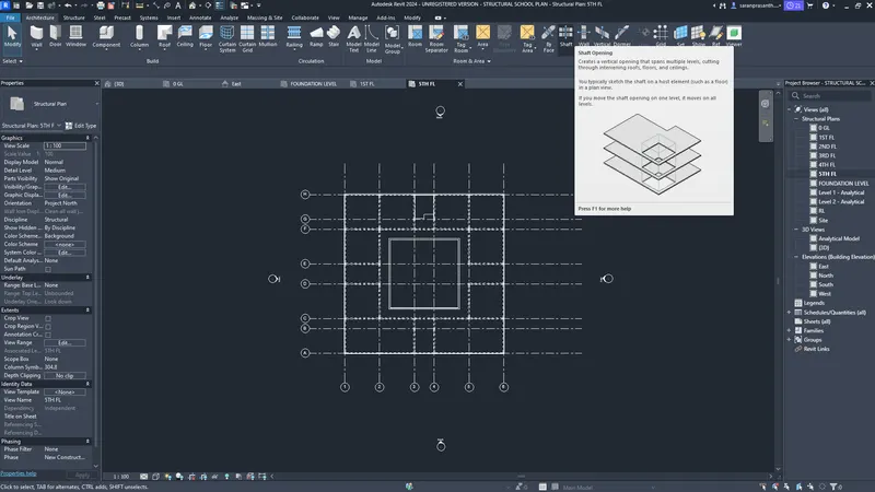
- Then stair case openning is use the tools and create the Shaft Open.
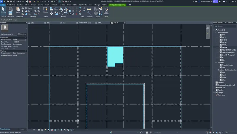
- The shaft is create sucessfully, shown in below 3d view
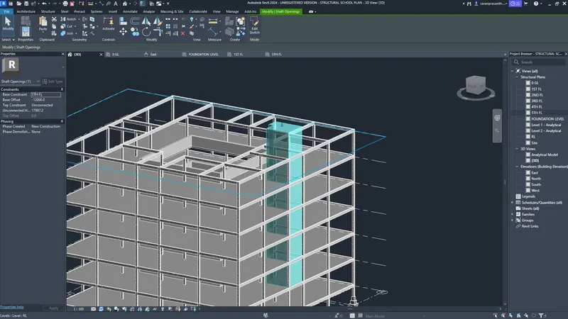
RESULT:
- The Using the Structural Model following the component of Footing, Column, Beam, Floor, Wall, and Shaft opening
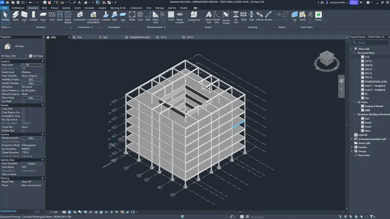
4) Using the architectural model, include the following components based on the type of structure selected
a. Wall Layout with appropriate material and finishing
b. Exterior façade with fancy finish
c. Interior partition walls to size rooms
d. Components to add details to a room ( Desk, Chair, Lighting, Plumbing fixtures)
e. Add components such as stairs Elevators
f. Have at-least one side of the building with curtain walls and glass panels
g. Include interior and exterior lighting fixtures
h. Place proper topographic components from outside ( Trees, Parking, Plants) to add details to the model
AIM:
- To using the architectural model, include the following components based on the type of structure selected
a.Wall Layout with appropriate material and finishing
b. Exterior façade with fancy finish
c. Interior partition walls to size rooms
d. Components to add details to a room ( Desk, Chair, Lighting, Plumbing fixtures)
e. Add components such as stairs Elevators
f. Have at-least one side of the building with curtain walls and glass panels
g. Include interior and exterior lighting fixtures
h. Place proper topographic components from outside ( Trees, Parking, Plants) to add details to the mode
PROCEDURE:
STEP1: TO OPEN ARCHITECTURAL TEMPLATE:
- Open the Revit Software.
- Then the Create the Architectural template in Models.
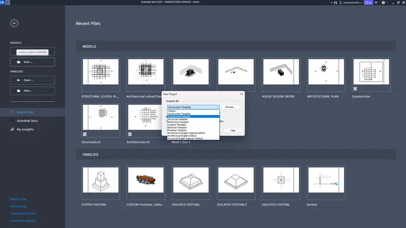
STEP 2: TO SET THE PROJECT BASE POINT:
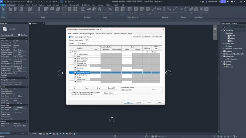
- Go to the Visibility Graphics and Shortcut is "VG"
- One Dialouge box are show.
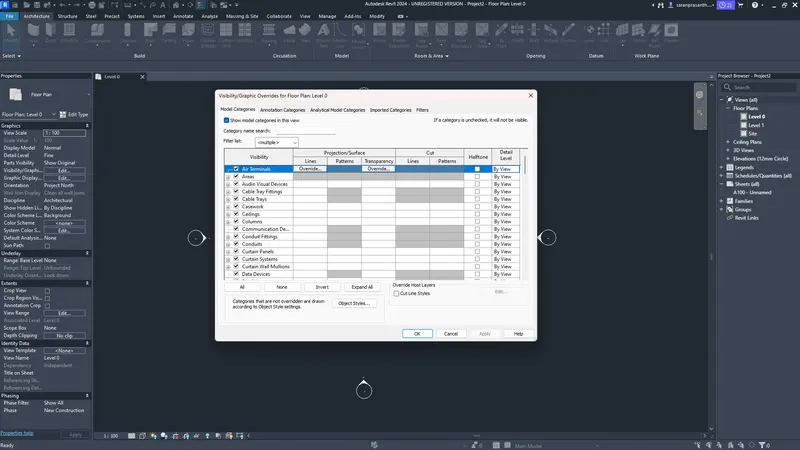
- That Visibility Dialouge Box there is Search tab to Search the "Site"
- Then the project Base Point to Select and tick, then Ok.
- The project Base Point is Created in the Architectural Plan.
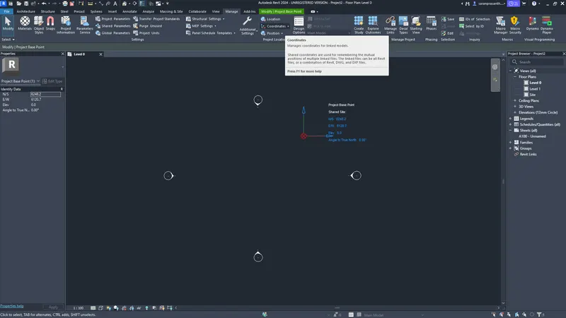
- That Symbol of Project Base Point to moved the Coordinate point created
- Go to the Manage Tab, then the Project Location column there is Coordinate to click.
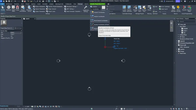
- Then Select the Specify Coordinate at Point to Click
- Then Select the Specified Coordinate at a Point to Select Shown in Below
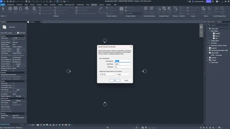
- After clicking one dialouge box will be open , Shown in Below
- The value is given 0
- After given the value , the Coordinate Point set at the Project Base Point
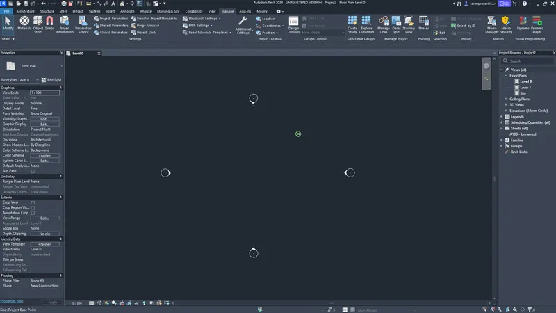
STEP3: TO LINK THE STRUCTURAL PLAN TO ARCHITECTURAL PLAN:
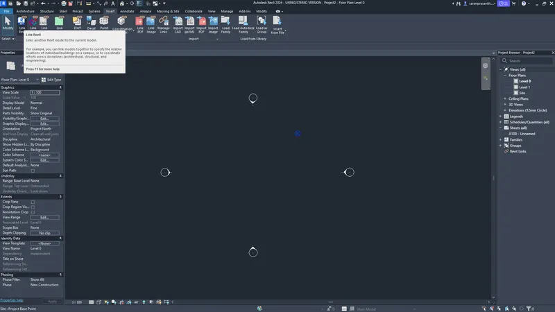
- After set the Project base Cordinate , Go to the Insert Tab.
- There is Link Revit option to click that, shown in below.
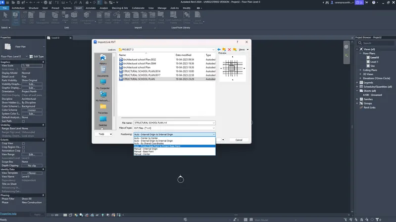
- Then open File location. Where will save the Structural Plan that path to be Open.
- Select the Structural Plan, Position is give Project Base Point to Project Base Point, then open the file
- how to do is shown in below
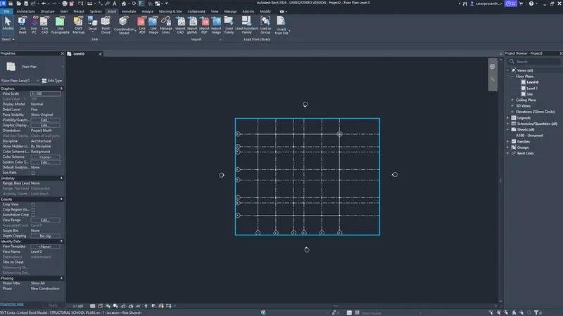
- After open the Structural Plan is Linking Sucessfully, shown in below.
STEP 4: TO CREATE THE GIRDS AND LEVELS USING COPY MONITER:
- The Grids and Levels are the copied from the Structural Plan by using the Copy Monitor tool.
- Go to the Collaborate tab and Coordinate Column their is Copy Monitor tools click the tool.
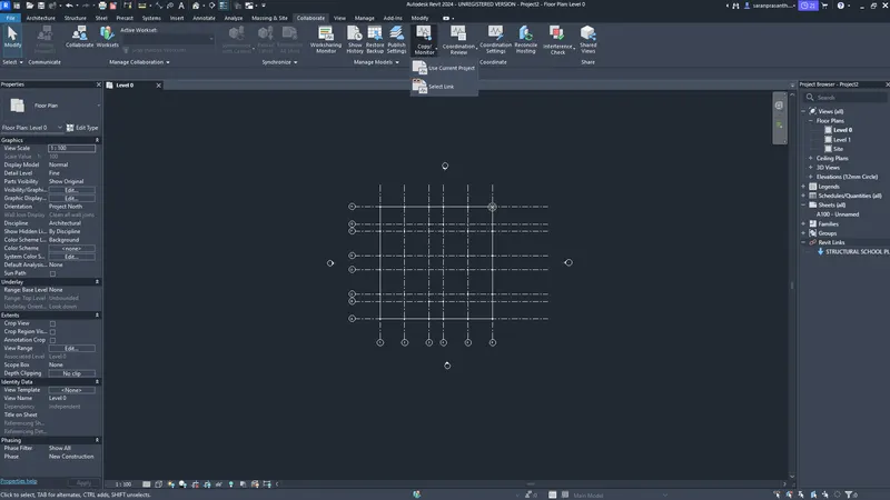
- Then the choose the Select Link tool, shown in below.
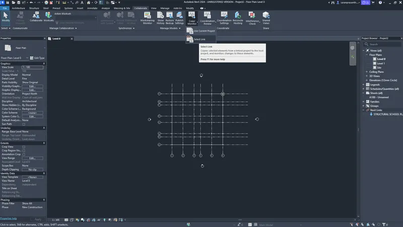
- Click the Select link option , then you select the Structual Plan Link in the Architectural Plan
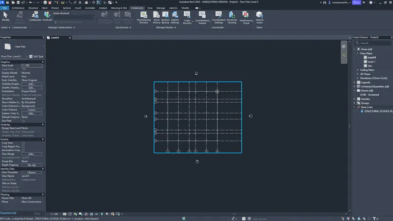
- Then the Ribbon as changed in the Copy Monitor tool
- Click the Copy and Below line is Multiple option is click to tick
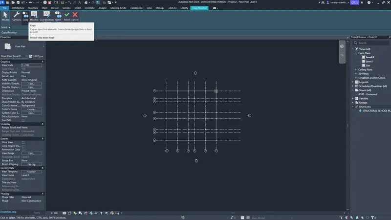
- Select the all diagram in the Plan View , then Filter only grids
- Then Click to Finish and again go to the Copy Monitor tap then again click to Finish.
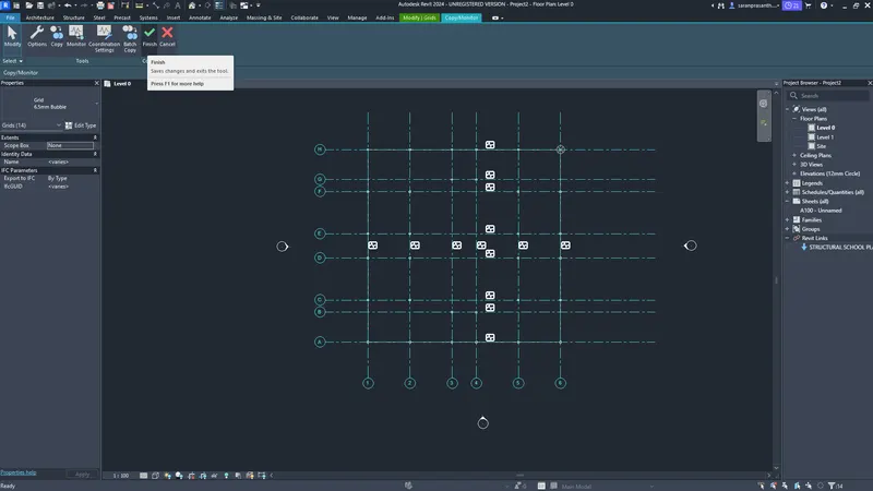
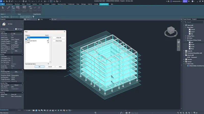
- Same Process to the Levels are Copied by using Copy Monitor tool
- Go to the 3D view , Select all element then filter the only Levels
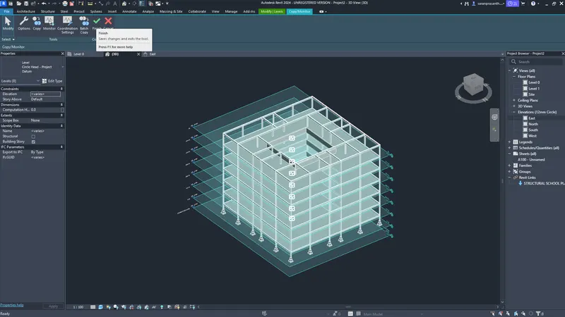
- Select the all diagram in the Plan View , then Filter only grids
- Then Click to Finish and again go to the Copy Monitor tap then again click to Finish.
- Then Now unlink the Structural Plan in the Visibility Graphics
- Go to the Visibility Graphics Shortcut is "VG".
- The Dialouge box are Open, the last tab is Revit link option their click it.
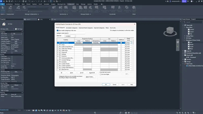
- Go to the Revit Link tab , shown in below
- Untick the Structural Plan, then Ok and apply it.
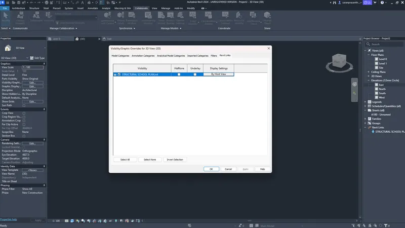
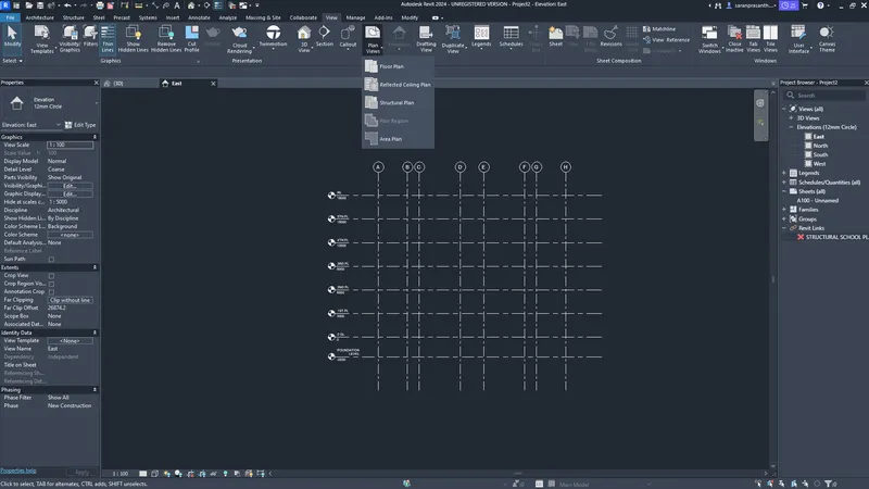
- The levels are not showing the Project Browser in Floor Plan View.
- Go to the View tap, shown in below.
- Select the Floor Plan option, then Dialouge box are open.
- That Dialouge box levels are shown , Select the all Level and Finish it,
- Now you see the Right side Project Browser below floor plan all levels are shown.
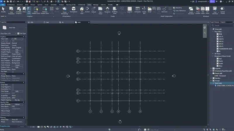
STEP 5: TO PLAN LAYOUT ARE CREATE PROPER FINISHIG WALL
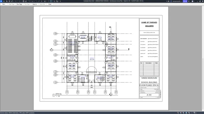
- School building size is 24000mmx24000mm
- After link the Structural Plan is create the walls in Architectural Plan.
- My Exterior Wall size is 200mm, Not using the Interior partition wall.
- Wall is proper finishig to created in Brick wall.
- Brick Wall is 180mm , inner and external finshing is 20mm thickness
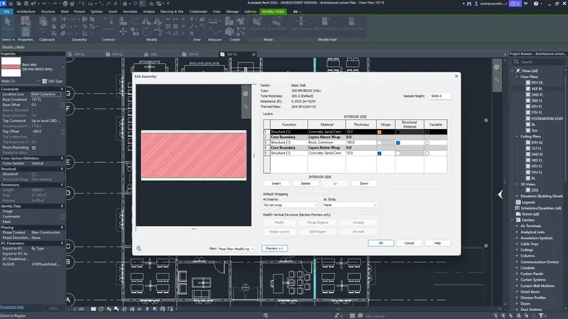
- The Plan layout is Create walls in Architectural plan using refrence Structural Plan.
- Class Room size is 5000mmx5000mm.
- Multi Purpose Hall size is 5000mmx10200mm.
- Staff room, Library, Vistor room, Principal Room size is 5000mmx4000mm.
- Toilets size is 5000mmx2800mm
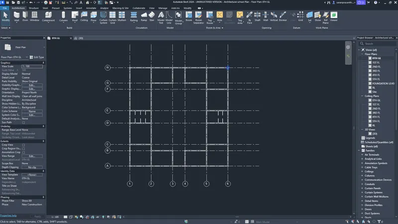
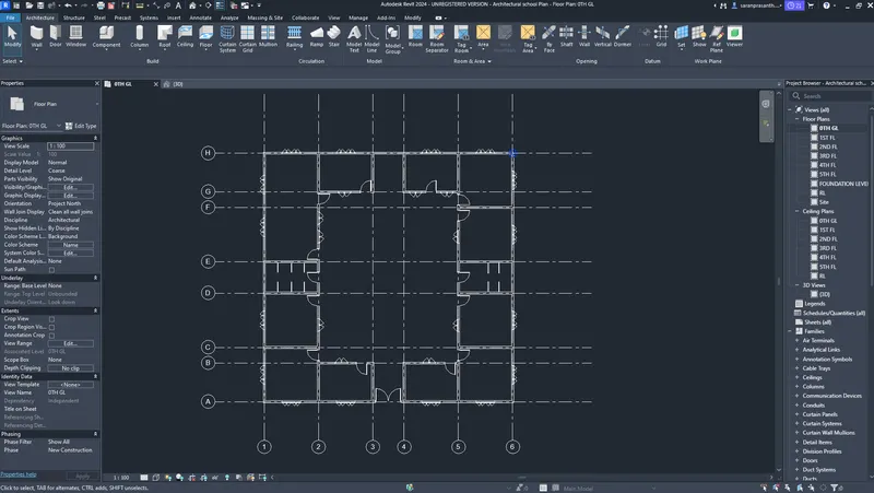
- The create the Doors and Windows in the Structural Plan, Shown in Below.
- The Main Door Size is 2400mmx2400mm and Door size is 1000mmx2400mm to placed
- The Window (W) size is 1800mmx1500mm and The Window (W1) size is 1800mmx1500mm to placed
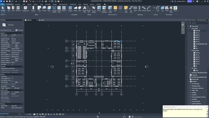
- Then the Components to be added in the Architectural plan.
- School building Components are added in Furniture and systems Plumbing Fixture, lighting and ect,,.
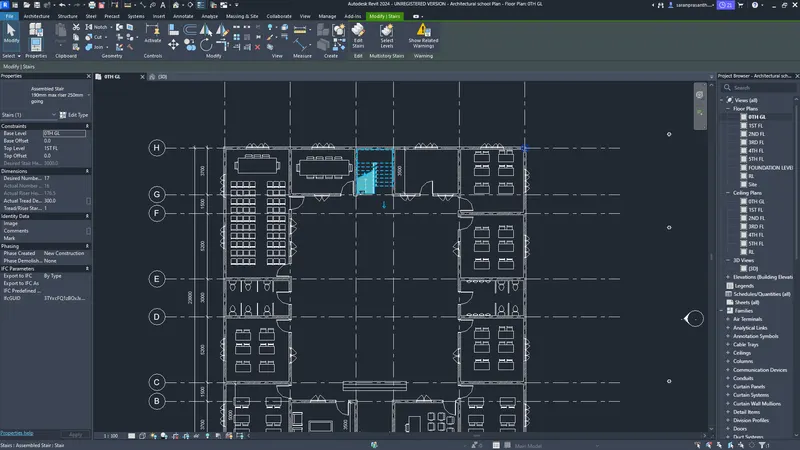
- The Stair case to be Provided in the Arichitectural Plan
STEP 6: TO COPY THE ARCHITECTURAL ELEMENT PLACED LEVELS:
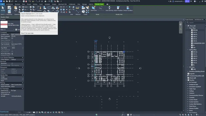
- Select the Architectural Element , Ribbon is changeed the Modify Tab
- There is Copy Symbol to Click , Shown in Below.
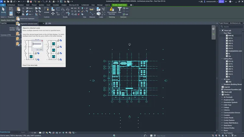
- Then the Paste symbol there to click that and select the Asigned to select levels. Shown in Below
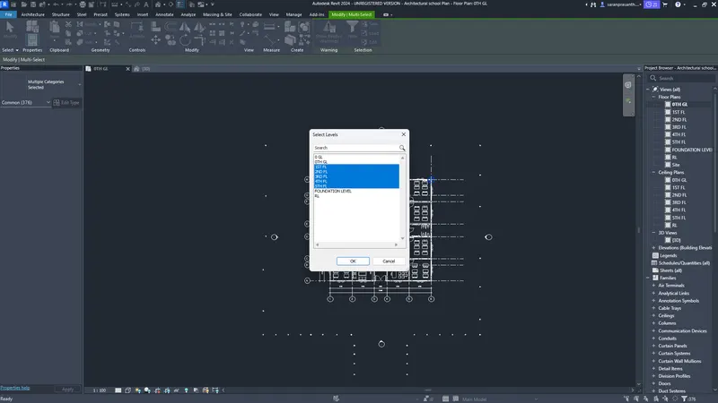
- Select the levels you paste the Architectural element, Shown in Below
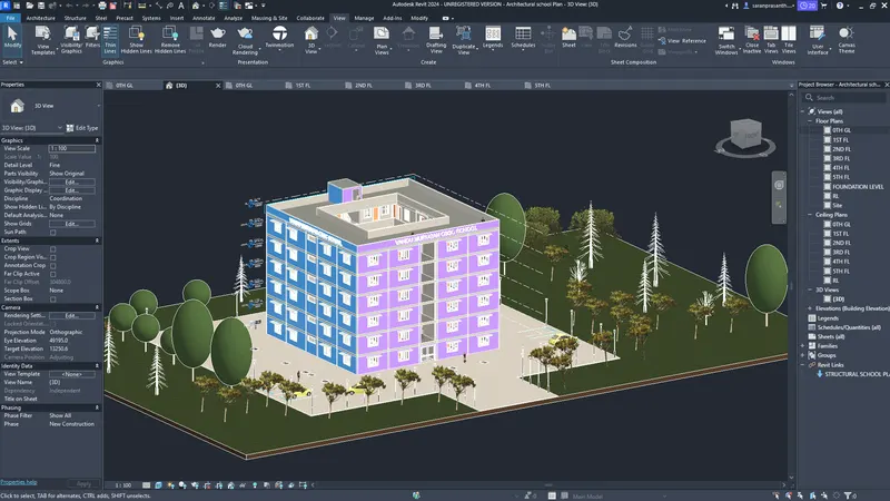
- After Placed the Architectural Components showing the 3D view
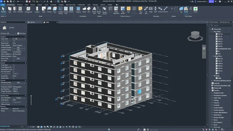
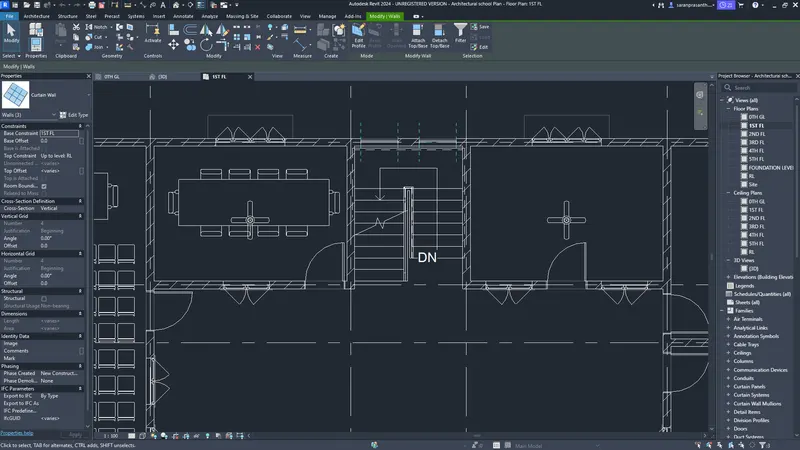
- The Front and Back Place to create the curtain walls
- That Curtain Walls as provided first floor to Roof level.
STEP 7: TO CREATE THE INTERIOR AND EXTERIOR LIGHTING:
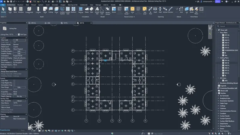
- Creating the celling of each floor then celling light as be provided.
- Lighting as provided in outsid and inside of the building.
STEP 8: TO CREATE THE TOPOGRAPHIC:
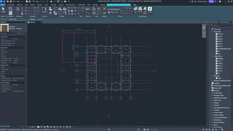
- Go to the Massing and Site then Toposolid is to click it.
- Draw a toposolid using draw tool.
- Above the toposolid to create the floor is thickness of 100mm.
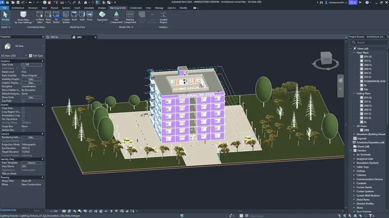
- The topographic Components are to create the site Component and Parking Components
RESULTS:
- The Architectural Plan as to be created the Wall Layout with appropriate material and finishing, Exterior façade with fancy finish Interior partition walls to size rooms Components to add details to a room ( Desk, Chair, Lighting, Plumbing fixtures), Add components such as stairs Elevators Have at-least one side of the building with curtain walls and glass panels, Include interior and exterior lighting fixtures, Place proper topographic components from outside ( Trees, Parking, Plants) to add details to the mode is all done the Architectural Plan
5) Provide a set of drawings in an architectural and structural model to list the following details with categories and appropriate sheet templates included
a. Floor Plans with Annotations
b. Elevations
c. Sections
AIM:
To Provide a set of drawings in an architectural and structural model to list the following details with categories and appropriate sheet templates included Floor Plans with Annotations, Elevations and Sections.
PROCEDURE:
STEP 1: TO CREATE THE SHEETS:
- Go to the view tab their is Sheet composition column top is Sheet is Click.
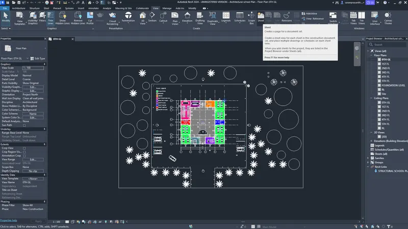
- After clicking that Sheet isone dialouge box open
- Then which sheet you want that is click load and choose the which type of sheet(A0,A1,A2,A3,A4).
- Then click the sheet and ok.
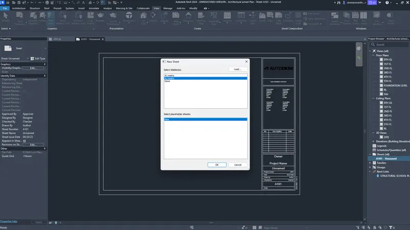
- Load the sheet and the revit display.
- If you want any edit to select the sheet and go to the Edit family.
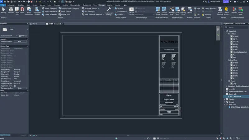
- Project detailed to be filled in the sheet is go to the Manage tab and choose the Project Information
- Fill the all detail the Project infoemation
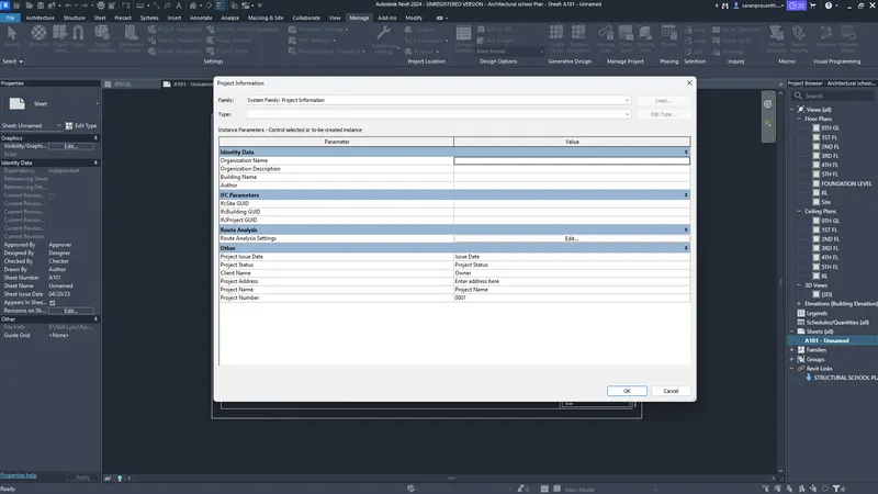
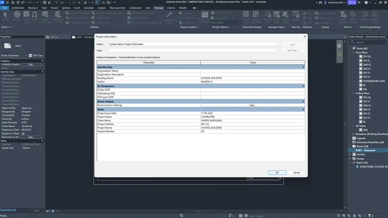
- Then Ok it.
STEP 2: TO APPROPRIATE SHEET INCLUDE THE FLOOR PLANS
ARCHITECTURAL FLOOR PLANS:
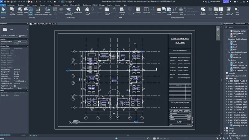
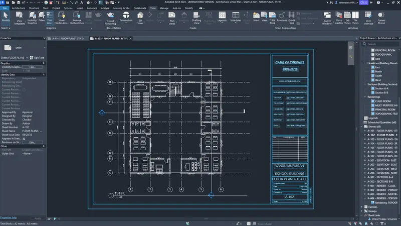
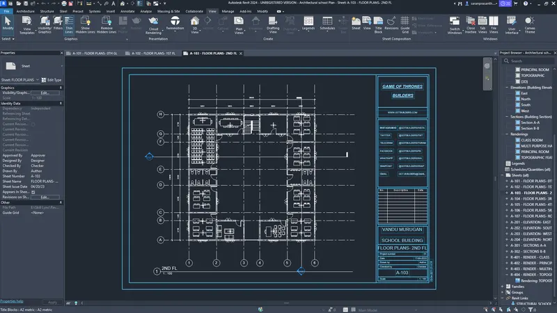
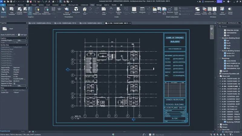
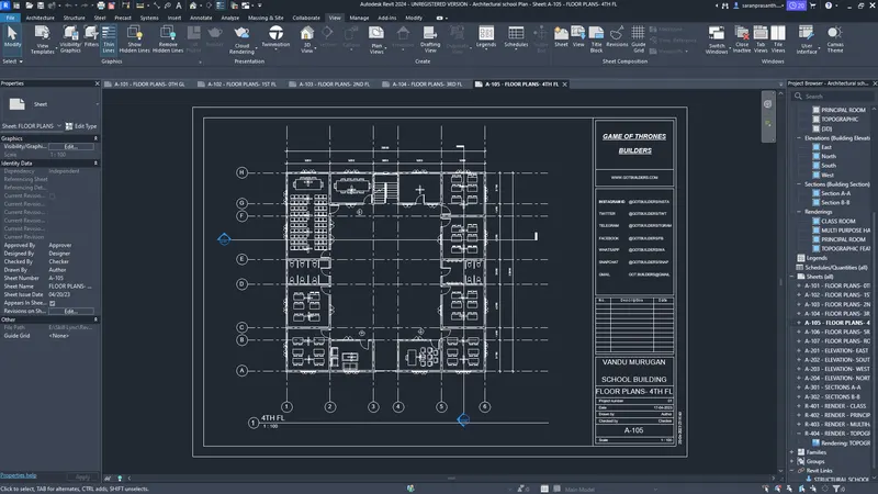
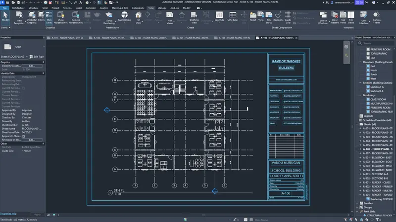
- After sheet to created the Floor Plan is drag on the sheats
- The scale is 1:100 to the sheet
- annotate the grid line distance
GROUND FLOOR:
FIRST FLOOR:
SECOND FLOOR:
THIRED FLOOR:
FOURTH FLOOR:
FIFTH FLOOR:
ROOF LEVEL:
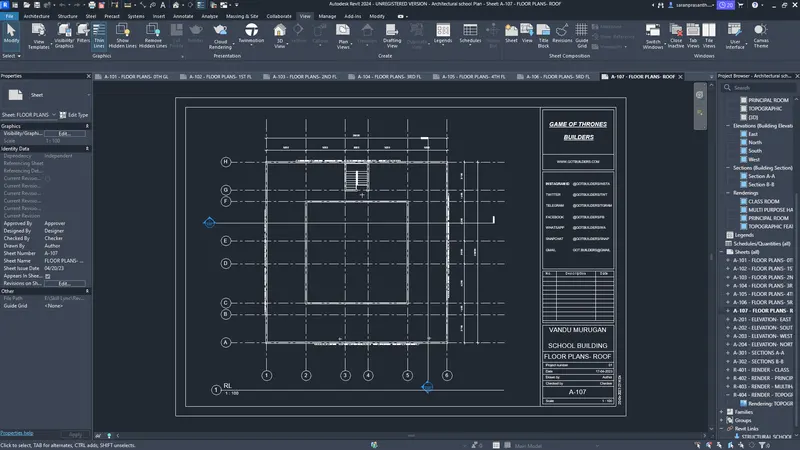
STRUCTURAL FLOOR PLANS:
- Sheet to create the structural plan is same Process.
- The structural plan is similar to the all floor so if i Show only the Ground and First and Roof.
GROUND FLOOR:
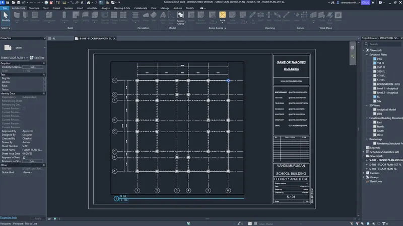
FIRST FLOOR:
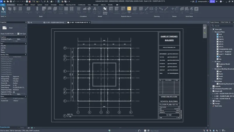
ROOF LEVEL:
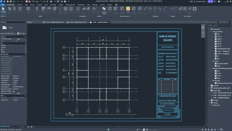
STEP 3: TO APPROPRIATE SHEET INCLUDE THE ELEVATION PLANS
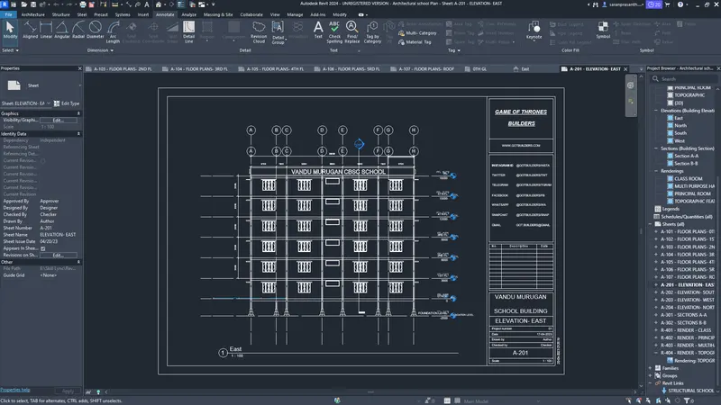
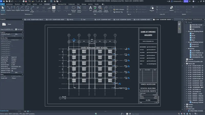
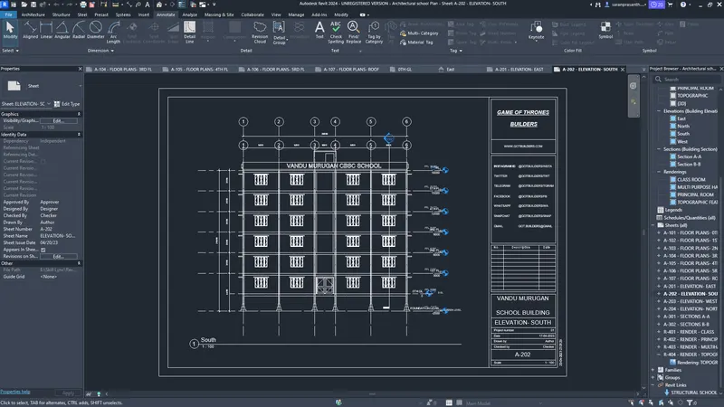
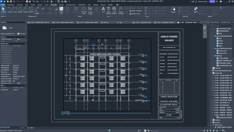
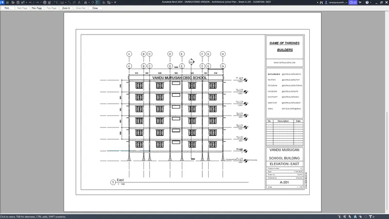
- The elevation of the building is all Direction
ARCHITECTURAL PLAN:
EAST:
NORTH:
SOUTH:
WEST:
STEP 3: TO APPROPRIATE SHEET INCLUDE THE SECTION PLANS:
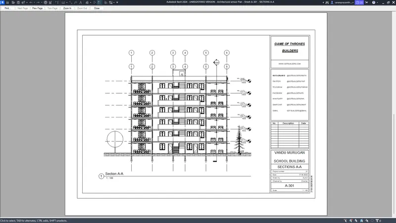
- The section cut is one Horizontal Direction is Section A-A and Vertical Direction is Section B-B
ARCHITECTURAL PLAN
SECTION A-A:
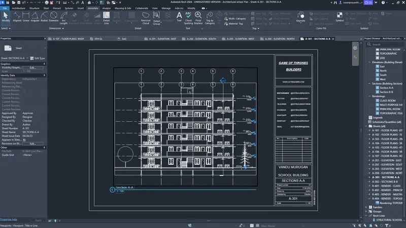
SECTION B-B:
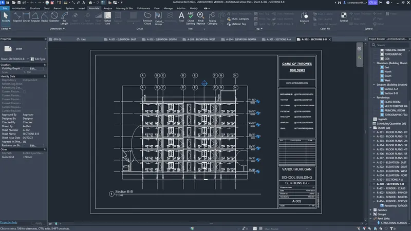
RESULT:
- The Sucessful create the sheet on Elevation, Section and Floor Plans
6) Using the Rendering settings, Render images of the 3D model produced and include the rendered images to the drawing sheets
a. Rendering from interior rooms
b. Rendering from out showing topographic features
c. Rendering through structural framing
AIM:
- To Using the Rendering settings, Render images of the 3D model produced and include the rendered images to the drawing sheets
a. Rendering from Interior rooms
b. Rendering from out showing topographic features
c. Rendering through structural framing
PROCEDURE:
STEP 1: TO RENDERING FROM INTERIOR ROOMS:
- First to set the Camara, that Camara is select from go to the view tab and list out the 3D View select the Camara.
- set the camara view on the Multipurpose hall.
- Then the rename 3d view of the camara view.
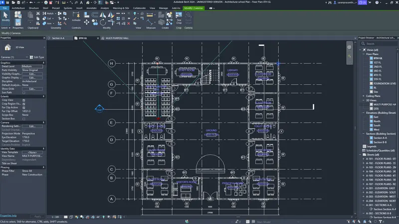
- Same tab the Render option to click
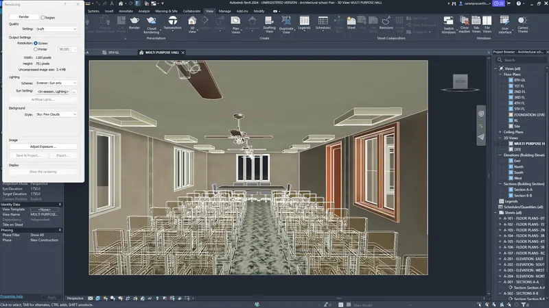
- Some option to change the render of dialouge box
- Lighting as change the internal sun and artificial
- start the rendering below
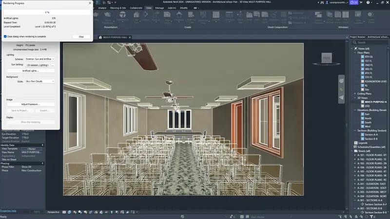
- Complete the render shown in below
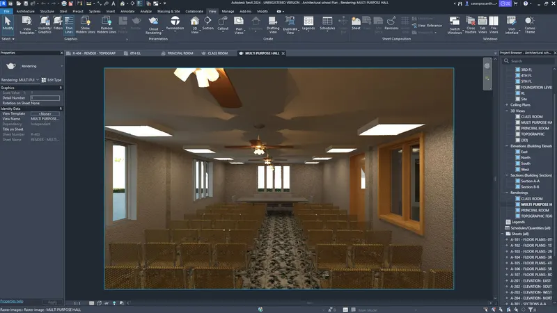
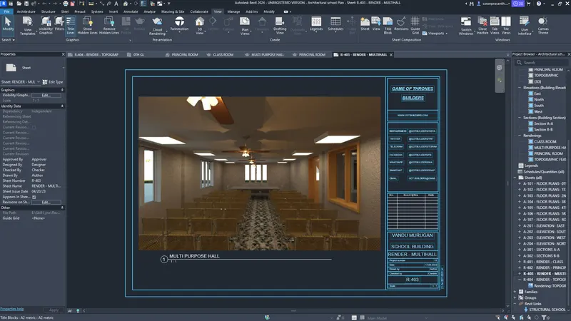
- Then the render complete if sheet to be created
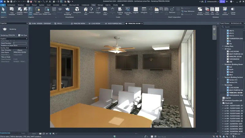
PRINCIPAL ROOM:
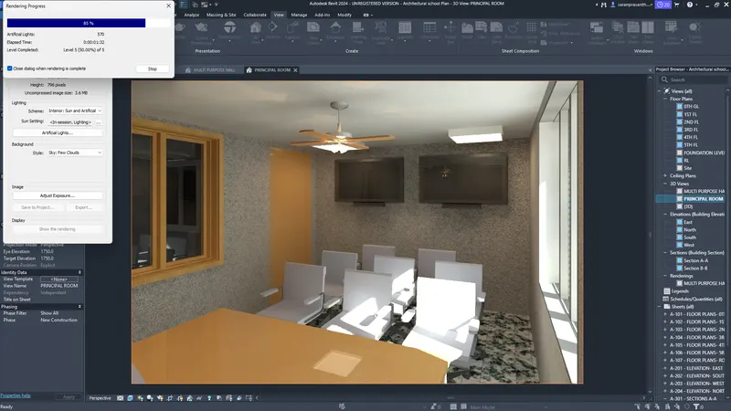
- Complete the render shown in below
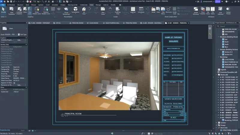
- Then the render complete if sheet to be created
CLASS ROOM:
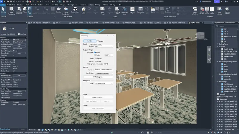
- Complete the render shown in below
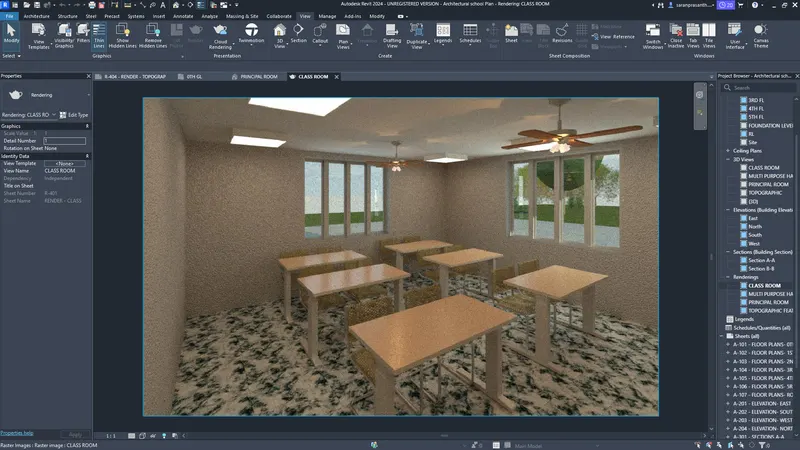
- Then the render complete if sheet to be created
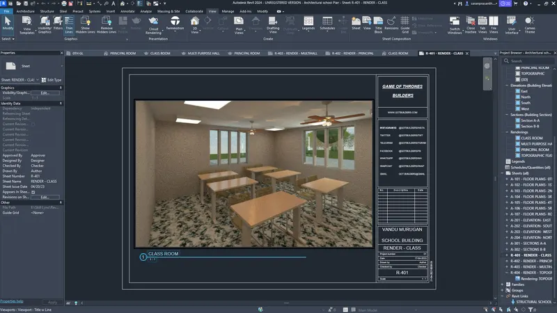
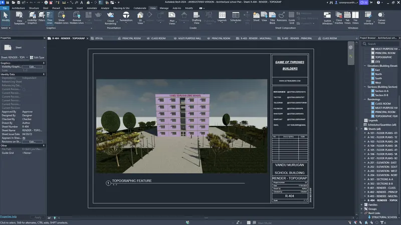
STEP 2: TO RENDERING FROM OUTSHOWING THE TOPOGRAPHIC FEATURES:
- First to set the Camara, that Camara is select from go to the view tab and list out the 3D View select the Camara.
- set the camara view on the outside.
- Then the rename 3d view of the camara view.
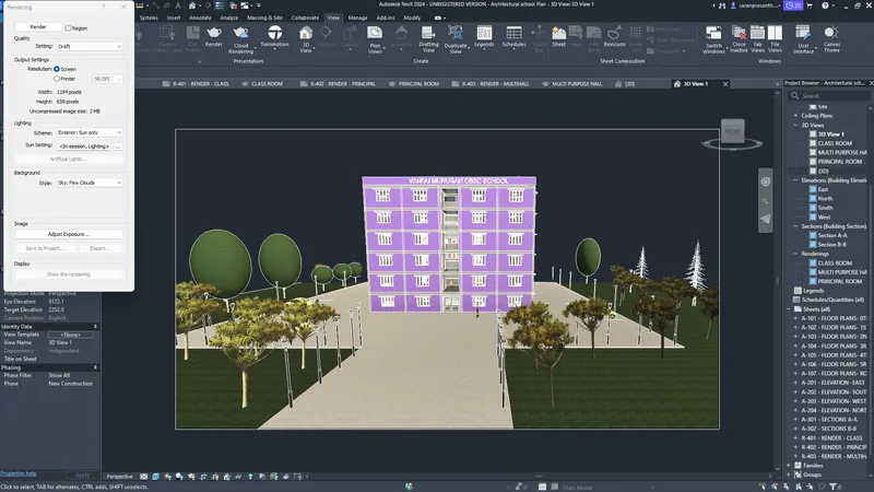
- Some option to change the render of dialouge box
- Lighting as change the external sun and artificial
- start the rendering below
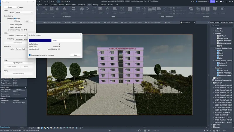
- Complete the render shown in below
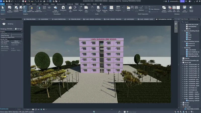
- Then the render complete if sheet to be created
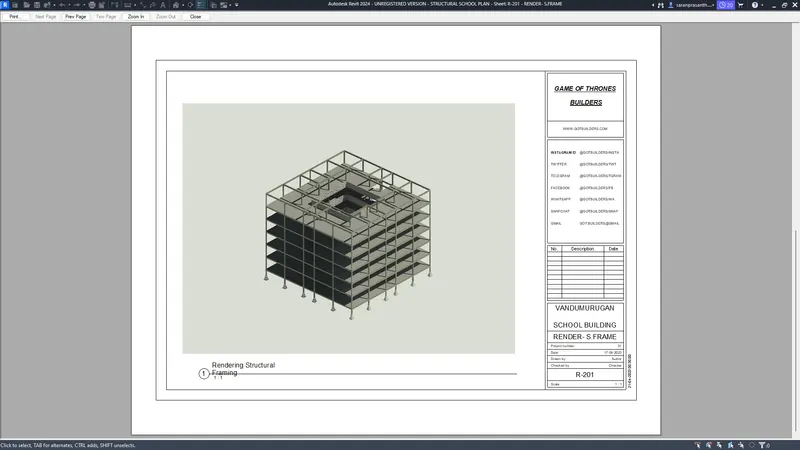
STEP 3: TO RENDERING FROM STRUCTURAL FRAMING:
- First to set the Camara, that Camara is select from go to the view tab and list out the 3D View select the Camara.
- set the camara view on the outside.
- Then the rename 3d view of the camara view.
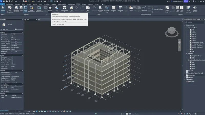
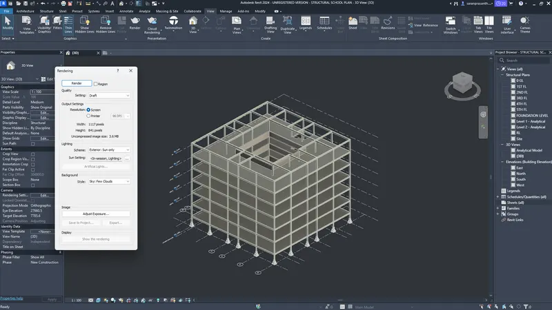
- Some option to change the render of dialouge box
- Lighting as change the external sun and artificial
- start the rendering below
- Complete the render shown in below
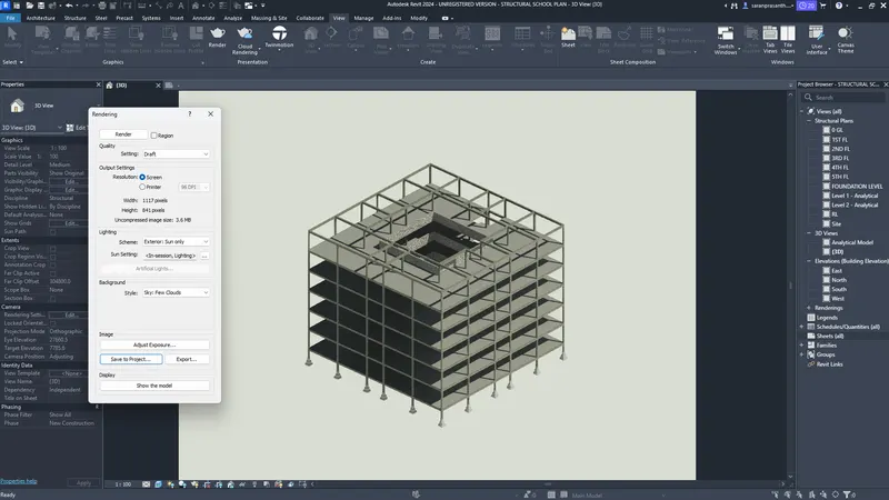
- Then the render complete if sheet to be created
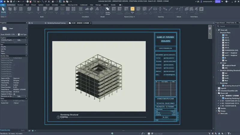
RESULT:
- The Using the Rendering images to the drawing sheets Rendering from Interior rooms, Rendering from out showing topographic features and Rendering through structural framing.
7) Print the set of drawing sheets created and submit the drawings from the architecture and structure model?
AIM:
- To Print the set of drawing sheets created and submit the drawings from the architecture and structure model
PROCEDURE:
STEP 1 : TO CREATE THE PDF OF DRAWING SHEET:
ARCHITECTURAL PLANS:
- Go to the file
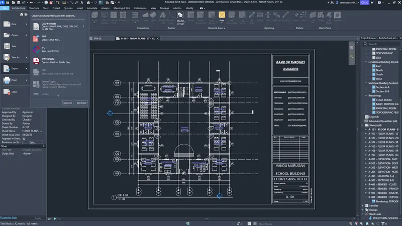
- Click to the Print Option
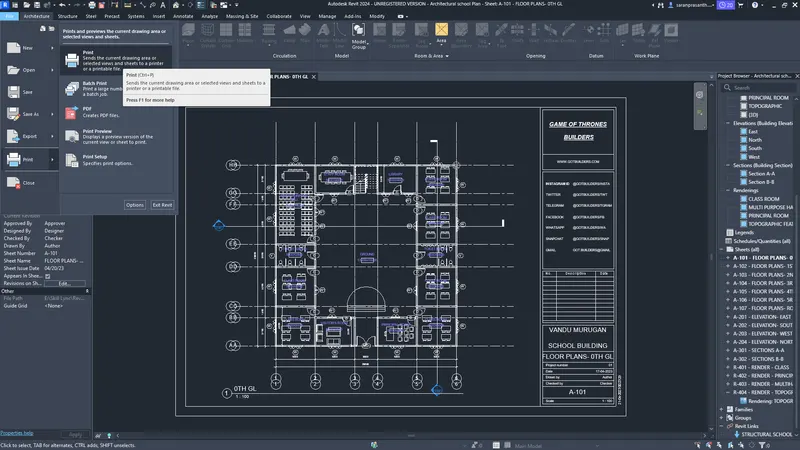
- Show the dialouge box is modify the printer name or PDF and landscpe or Portrite
- The Check Before the Preview Option to Clik the bottm
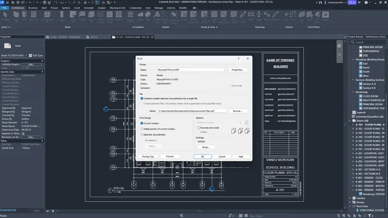
- Check the File before the alignment and click to Print
ARCHITECTURAL GROUND FLOOR LEVEL:
ELEVATION (EAST)
SECTION A-A
STEP 2: TO CREATE THE PDF OF DRAWING SHEET:
STRUCTURAL PLAN
- Go to the file
- Click to the Print Option
- Show the dialouge box is modify the printer name or PDF and landscpe or Portrite
- The Check Before the Preview Option to Clik the bottm
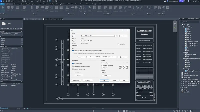
- Check the File before the alignment and click to Print
STRUCTURAL PLAN GROUND FLOOR LEVEL:
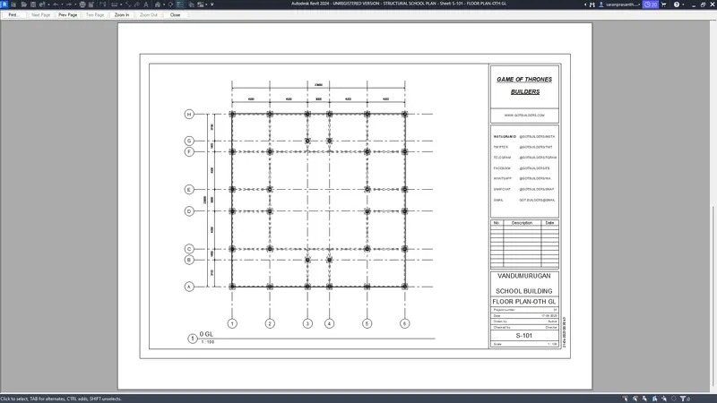
STRUCTUAL FRAMING: