Sketch a G+1 residential plan according to Vaastu Shastra and Calculation of Loads as per IS code
Question
Sketch a G+1 floor residential plan, according to Vaastu Shastra, and list down the names of the structural drawings required to be provided to the site for construction.
Also, assume the sizes of the structural elements (Column, Beam, Slab, etc.,) and accordingly calculate the individual corresponding loads from the members as per IS code.
Your Answers
AIM:
To draw a G+1 floor residential plan according to the Vaastu Shastra and to list down the names of structural drawings required to be provided to the site for construction.
To assume the size of structural elements (Column, Beam, Slab, etc,) and to calculate the loads from the members as per IS code.
INDIAN CODES AND STANDARDS USED FOR THE DESIGN :
IS456:2000; for reinforced concrete structures.
IS875:1987; (part I) for the dead load.
IS875:1987; (part II) for live load.
IS875:2015; (Part III) for wind load.
IS1893:2016; (Part I) for seismic load.
IS13920:1993 for seismic detailing.
INTRODUCTION :
Vaastu shastra is the ancient science of architecture and acts as a guideline to design a home in a way that enhances positive energy.
A good home needs to radiate the right kind of energy. A person dwelling in a house comes under the influence of a specific energy field which in turn influences him.
Vaastu shastra and ancient science propound such theories based on direction, architecture, astronomy, and even astrology.
Therefore, it is very crucial to understand the link between the healing act of Vaastu and our homes in spreading positivity and good vibes.
BASIC PRINCIPLES OF VAASTU SHASTRA :
Shape: Rooms should be preferably square or rectangle.
Room basics: Rooms should be airy, well lit, bright and clean.
Home center: Centre of the house should be a space.
Stairs and furniture: Heavy furniture should be kept in a southwest direction.
Water: Avoid keeping plants and water features in the bedroom.
Dining table: The dining space should be near the kitchen and not near the main door.
Mirror placement: Mirror-facing beds are strictly not allowed. Mirrors in the bedroom should be placed in such a way that the bed cannot be seen.
PROCEDURE:
G+1 floors residential plan is 25ft x40ft given below.
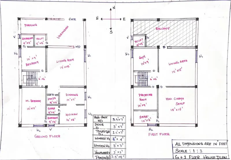
STRUCTURAL DRAWINGS THAT ARE TO BE DELIVERED TO THE SITE FOR CONSTRUCTION INCLUDE:
- Centerline drawing
- Footing and column layout with reinforcement details.
- Column schedule with reinforcement details.
- Plinth beam layout with reinforcement details.
- First-floor beam layout with reinforcement details.
- First-floor slab layout with reinforcement details.
The above-mentioned drawings will assist the site engineer to carry out the construction process in a systematic manner.
STEP1: GIVEN DATA
Column Size =300mm X 300mm
Beam Size=300mm X 400mm
Height of Building=3.5m
Slab Thickness=170mm
Exterior Wall thickness=230mm
Interior Wall thickness=140mm
STEP2: TO CALCULATE DEAD LOAD IS875:1987(Part I):
i) Dead load of column:
It is Reinforced Concrete Unit Weight of material is 25kN/m3
Dc=l*b*h* unit weight of RC material
Dc=0.3x0.3x3.5x25
Dc=7.875 kN
Since all columns are same size, Dead Load of other columns will also be 7.875 kN / Floor
ii) Dead load of Beam:
It is Reinforced Concrete Unit Weight of material is 25kN/m3
Here beam length calculated per 1m
Db= b*d* l* unit weight of RC material
Db=0.3x0.4x1x25
Db=3.0 kN/m
Since all beams are same size, Dead Load of other beams will be 3.0 kN/m
iii)Dead load of Slab:
It is Reinforced Concrete Unit Weight of material is 25kN/m3
Here Slab length calculated per 1m2
Dw= l* b*t* unit weight of RC material
Dw=1 x1x0.17x25
Dw=4.25 kN/m2
Since all slabs are same size, Dead Load of other slabs will be 4.25 kN/m2
iv)Dead load of Wall:
It is Brick masonry Unit Weight of material is 18kN/m3
Exterior wall
Here Wall length calculated per 1m
Dw= l* t*h* unit weight of Brick material
Dw=1 x0.23x3.5x18
Dw=14.49 kN/m
Interior wall
Dw= l* t*h* unit weight of Brick material
Dw=1 x0.14x3.5x18
Dw=8.82 kN/m
STEP3: TO CALCULATE LIVE LOAD IS 875(PART 2):1987
As per IS 875(PART 2):1987 table 1is
Uniform Distribution Load is
Bedroom = 2 kN/m2
Bathroom = 2 kN/m2
Kitchen = 3 kN/m2
Living /dining =2 kN/m2/4 kN/m2
Store = 3 kN/m2
Balconies = 3 kN/m2
Staircase = 3 kN/m2
STEP4: TO CALCULATE WIND LOAD IS 875 Part 3: 2015
According to the code, it is necessary to calculate the wind load only if the height of the building exceeds 10m. Here, the height of the building is 7.0m, which is less than 10m. Hence there is no need of calculating the wind load.
Assuming Building Height is 10m.
Wind loads calculation is use code book is IS 875 Part 3: 2015
i) Design Wind Speed
Vz = Vb*k1 *k2 *k3 *k4
Vb= Choose Chennai Location= 50
k1 = from (see 6.3.1, Table1), 50 year Design Value is = 1
k2 = (see 6.3.2.2 Table2), Category 4 10m height = 0.8
k3 = (see 6.3.3.1) as per site condition is not Slope = 1
k4 = (see 6.3.4) K4= 1
Vz =50 x1x0.8x1x1
Vz =40 m/s.
ii) Wind Pressure
Pz = 0.6 Vz2
Before step to calculate Vz are 40 m/s
Pz =0.6 * (40)2
Pz =0.6 * 1600
Pz =960 N/m2.
iii) Design Wind Pressure IS 875 Part 3: 2015
Pd = Kd*Ka*Kc*Pz
Kd= (See 7.2.1) Square , Rectangular = 0.9
Ka= (See 7.2.2 Table 4) Area of section is 92.903 m2 Ka=0.81
Kc= (See 7.3.3.13) value is 0.9
Pz= before step calculate is 960 N/m2
Pd =0.9x0.81x0.9x960
Pd =629.86 N/m2.
RESULT:
The load calculations are done as per IS code considerations
Dead load calculated as per the code, IS875:2015 (Part I) is obtained as follows :
The dead load of the column = 7.875 kN per floor.
The dead load of the beam = 3.0 kN/m
The dead load of the slab = 4.25 kN/m2.
The dead load of the External wall = 14.49 kN/m.
The dead load of the internal wall= 8.82 kN/m
Live load for a residential building is obtained from Table 1: Imposed Loads for different occupancies; of IS875:1987 (Part II)
Wind load is calculated as per the code IS875:2015 (Part III). Since the height of the building does not exceed 10m, there assume 10m height.
Design Wind Speed=40 m/s.
Wind Pressure=960 N/m2.
Design Wind Pressure=629.86 N/m2.