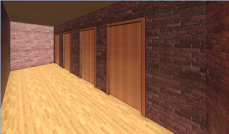
Creating Architectural and Structural model with 3D rendering using REVIT
1.Answer: The type of building choose is b. Office building
2.Answer: NBC Limitations are as follow
- The Open space around the building shall not be less than 4.5m
- The type of construction is Type 2 construction
- The FAR value for the business shall be take as 2.9
- The plat size is taken as 50m x 75m, hence the FAR value is satisfied
- The width of the road is 9m(30')
3. Answer:
Aim: To draft the structural model, of a office building, and to include the following deatails.
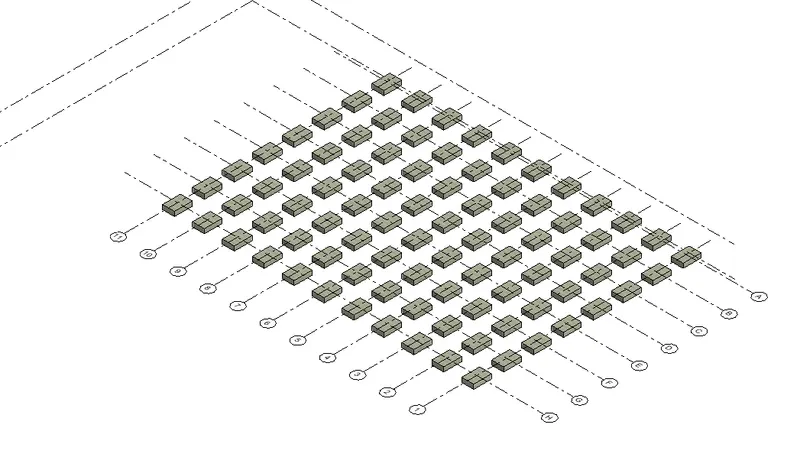
- Foundation - Isolated
- Columns height upto 10'
- Beams connected to columns
- Roof framing
- Floor
- Floor openings for the elevators
Procedure:
- For Foundation level: Open the new Architectural template -> create 6 horizontal as A, B, C, D, E, F, G and 6 vertical grids as 1, 2, 3, 4, 5, 6, click on the architectural tab -> selected isolated type of footing -> select for grids option -> select all the created grids -> Click on Right green tick mark -> Cross check the foundation in 3D
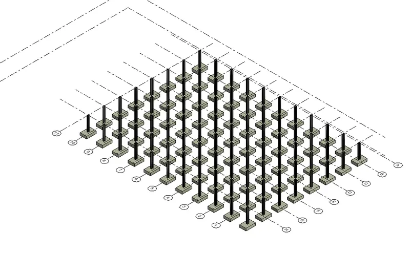
- For Columns: Click on the structural tab -> click on column -> choose vertical column -> select as option grids -> select for grids option -> select all the created grids -> Click on Right green tick mark -> Cross check the foundation in 3D To drag all the column at the roof level: Select all the columns -> Base level ground floor -> modify top level as second level -> then click apply.
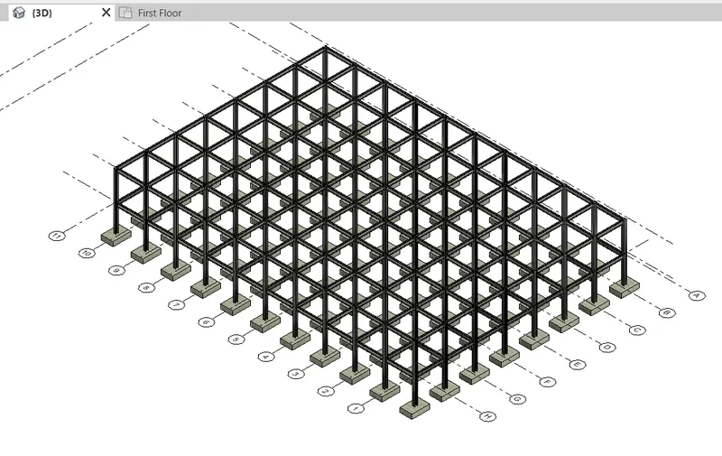
- Beams connecting with the columns: Click on the Ground level -> click on structural tab -> click on beam option -> choose the beam ( concrete R.S)-> Select the grid option -> select all grids -> click on the green right tick mark. simillary, repeat the procedure for the first floor, second floor to place the beams connecting with columns upto second level
- Floor: Click on Ground floor -> Click on the architecture tab -> drop down the option of floor -> select floor architectural -> choose rectangle option to create boundary -> finally click on the right green tick mark. simillary, repeat the procedure for the first floor, second floor to place the floor upto roof level.
- Roof on roof level: Provide the opening for the starir and elevator: Go to the architectural tab-> Click on the shaft -> select the rectangle option -> select the bounday of stair and elevator -> then finally click on the right green tick mark.
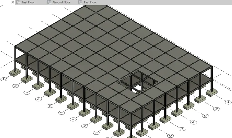
Result: The structural madel, of a office building is drafted and as shown below.
Revit Result:
4. Answer:
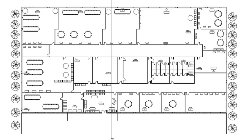
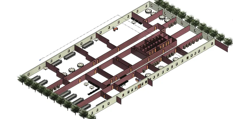
Aim: To insert all the componets required in a office building.
Procedure: In the plan view created, use the Load family option and insert the components like
- External wall layout
- Internal wall layout
- Doors
- Windows
- Sofa
- Employee desk
- Chairs
- Recieption area table and chair
- Lightings
- Round Table
- Conference table
- Restroom fixtures
- Parking utilities
- Tree
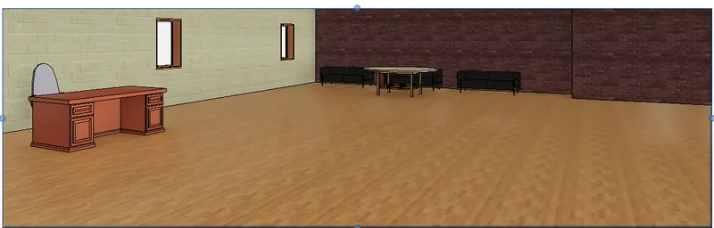
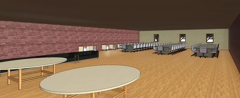
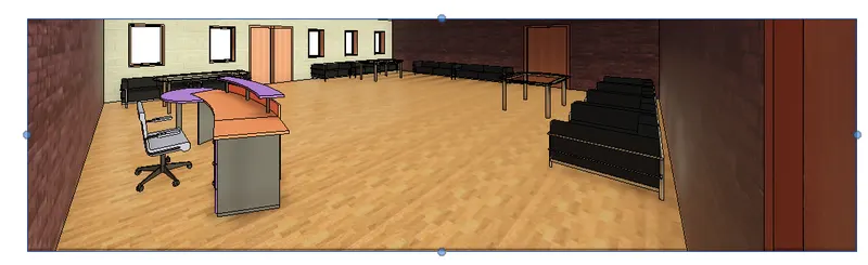
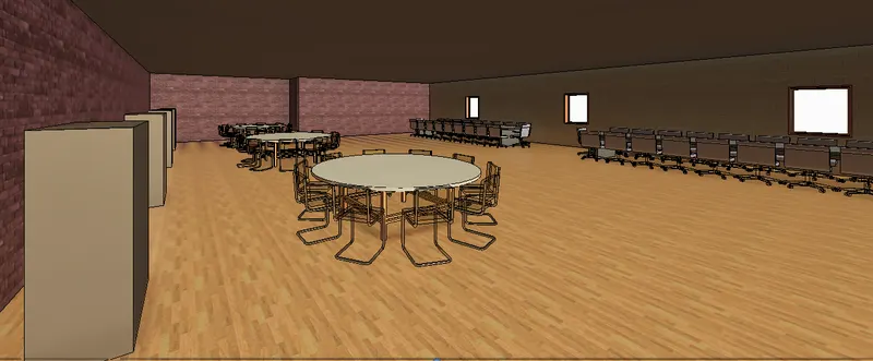
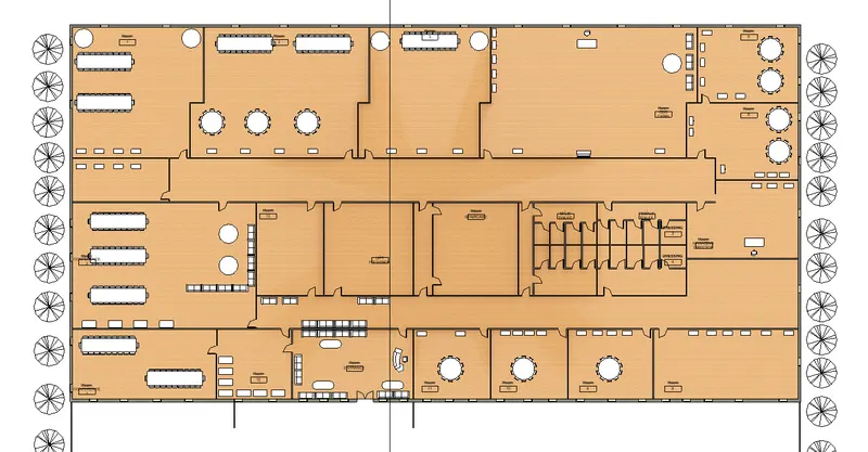
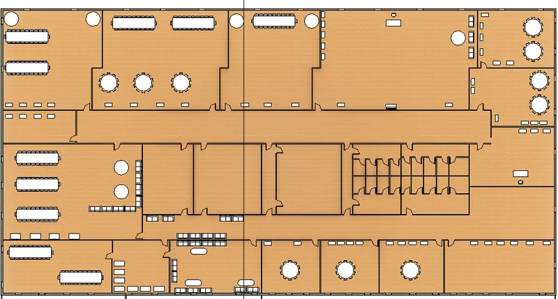
Result: All the required office building is inserted into the plan and can be seen in 3D view.
Revit Result: Place the camera in all the rooms to see the 3D view of the components fixtures placed.
5. Answer:
Aim: To insert the floor plan, elevation, sections in the sheets.
Procedure: Click on the sheet -> select the paper size -> drag the plan, elevation, sections, views into the sheets.
Result: The views inserted into the sheets and shown below
Revit Result:
GROUND FLOOR PLAN
FIRST FLOOR PLAN

NORTH ELEVATION

SOUTH ELEVATION
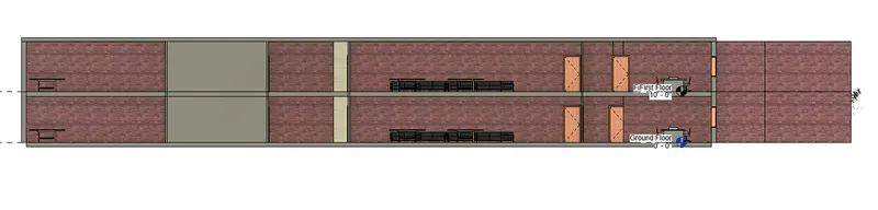
WEST ELEVATION
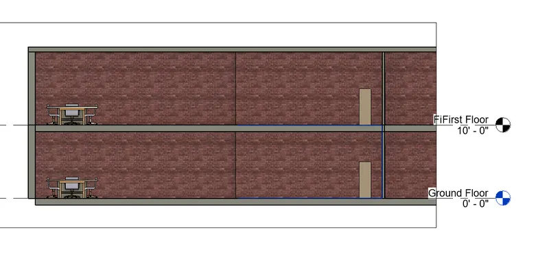
SECTION 1
6. Answer:
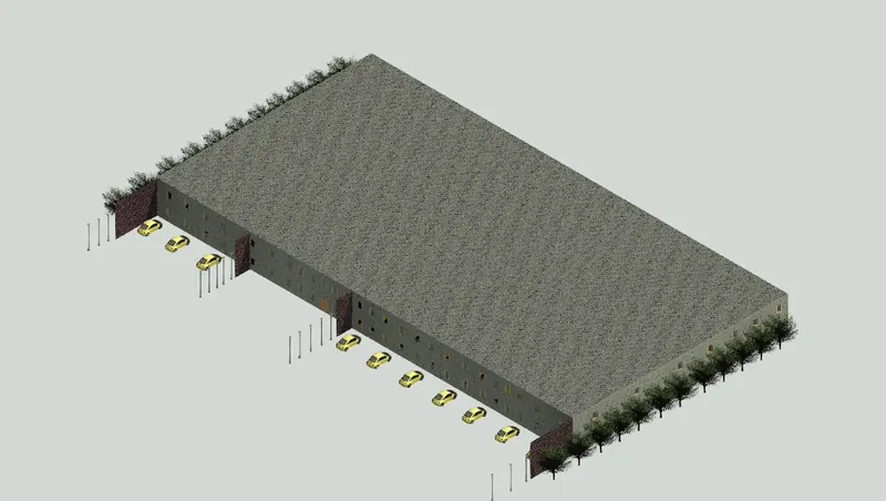
Aim: To render the 3D views and to create a sheet of render 3D views.
Procedure: Click on the view tab -> click on the render option or just rr -> select the required camera view -> click on render
Result: The 3D rendering of the sheets is created and as shown below.
Revit Result:
7. Answer:
Aim: To print or to save PDF of the sheets and the 3D camera views.
Procedure: Open the sheets or the 3D camera view that to be created as print or PDF file -> Click ctrl p -> Select the print/PDF option -> Save
Result: The PDF copy is created and attached below.