Creating Architectural and Structural model with 3D rendering using REVIT
1.
AIM:
Select the type of structure you want to build from one of the three below:
a. Multi-Unit Residential Apartment
b. Office Buildings
c. School.
These building condine both architectural model and structural model
architectural model condine all the architectural component like doors ,windows, furnitures ,some topographycal details...
Structural model condine columns,beems ,walls...
here iam selected 'OFFICE BUILDING'
2.
AIM :
Assume reasonable assumptions for geographic and location details for your project modeling.
Based on assumptions and type of structure selected identify the modeling requirements from NBC.
PROCEDURE :
my project is in plain area.
it is in commercial area.
MODELLING REQUIREMENTS FROM NCB ARE:
an exit must be provided in every building so as to permit safe escape of employes
in case of earthquake or fire hazards.
The open space around the building shall not be less than 4.5m
The type of construction as type 2 construction, the FAR value for the business building shall be taken as 2.9
The plot size is taken as 40m x70m
The width of the road abutting the building is taken as 9m
3.
AIM:
Using the structural model, include the following components based on the type of structure selected
a. Foundation – Isolated / Wall/Matt Foundation
b. Columns
c. Beams Connected to Columns
d. Roof Framing/ Truss
e. Floor / Decks
f. Floor Openings for Elevators and Stairs
PROCEDURE
open a revit software
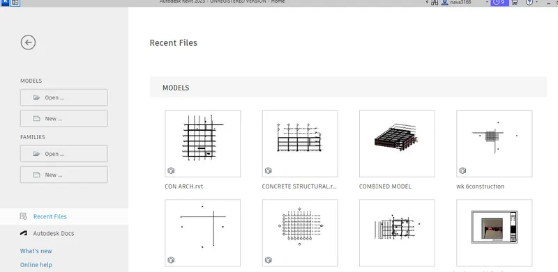
open architectural template
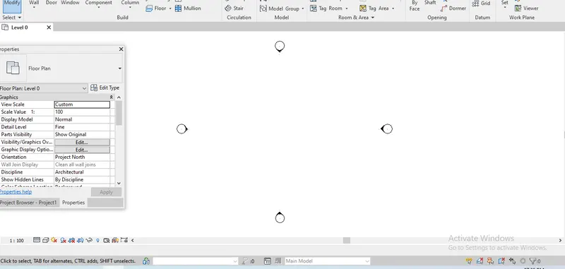
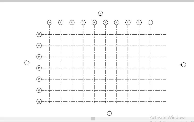
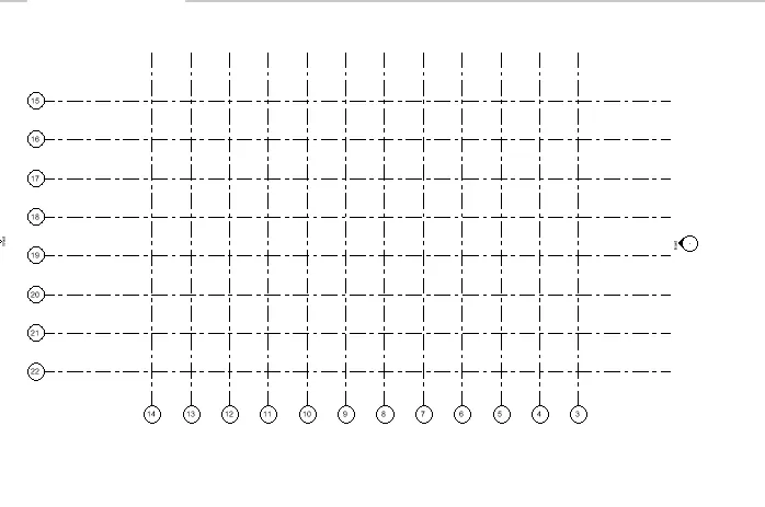
make horizontal and vertical grids
create varies levels and rename the levels
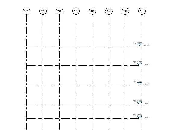
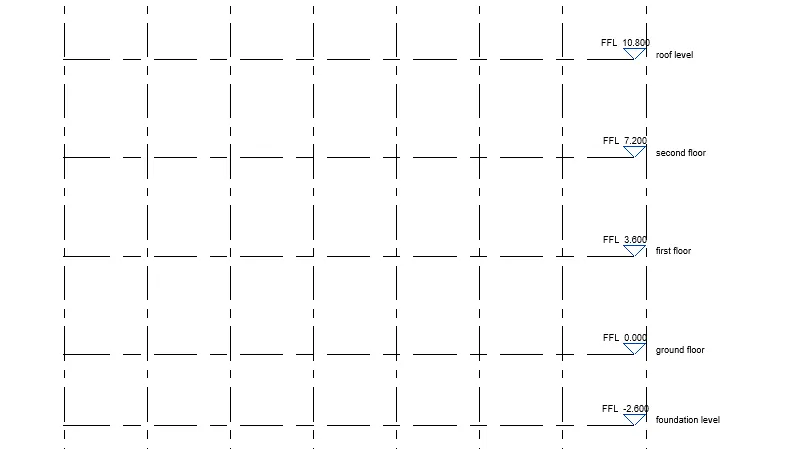
saelect the foundation level
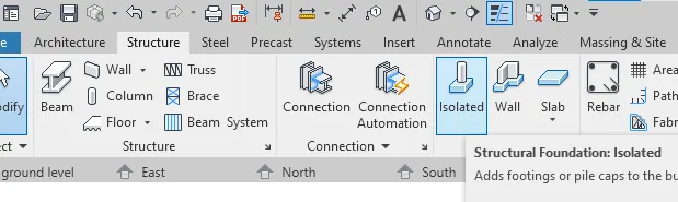
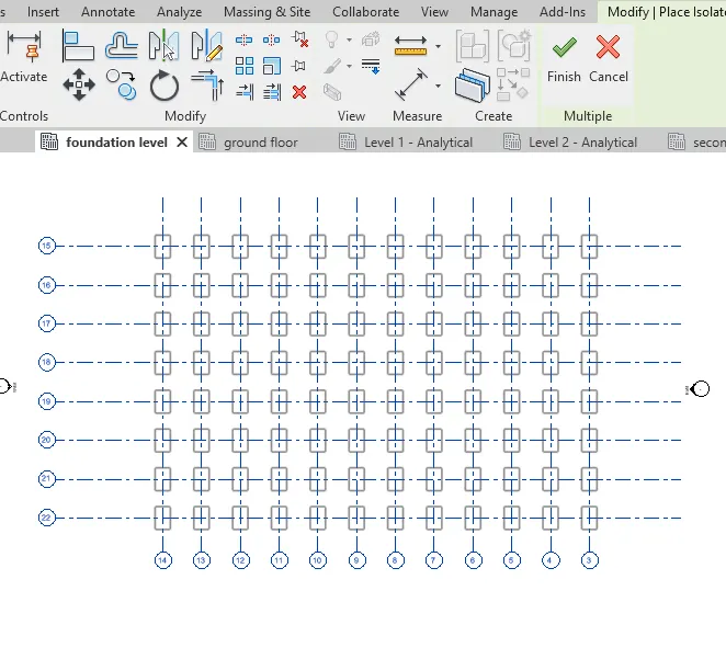
select structure click isolated foundation
select at grids select all the grids

then click finish
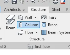
next draw the column for that select ground level and select structure column
select vertical column
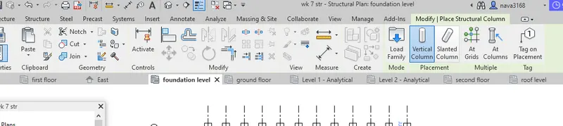
select at grids and select all the grids at ground floor
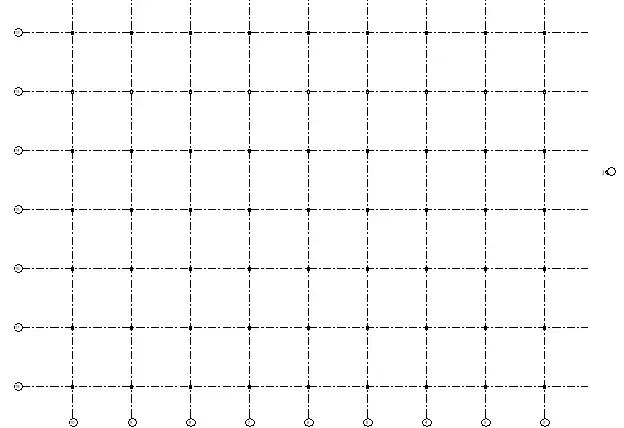
select 3d view
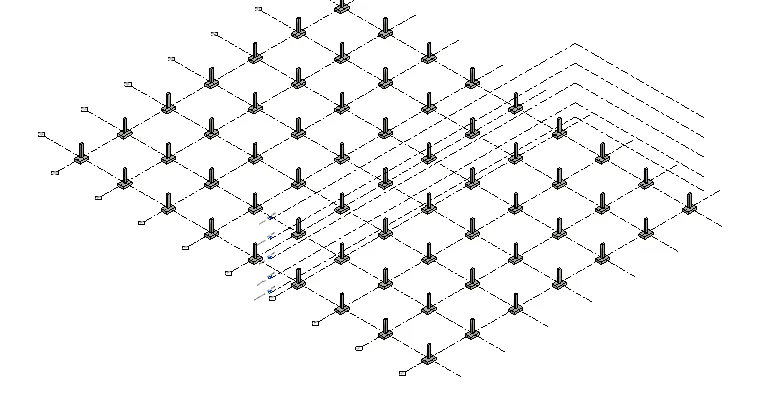
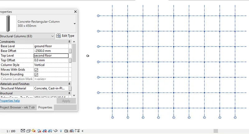
these column is only in ground floor we need to the column at the roof level for that select all the column and top level mis set as 2nd level
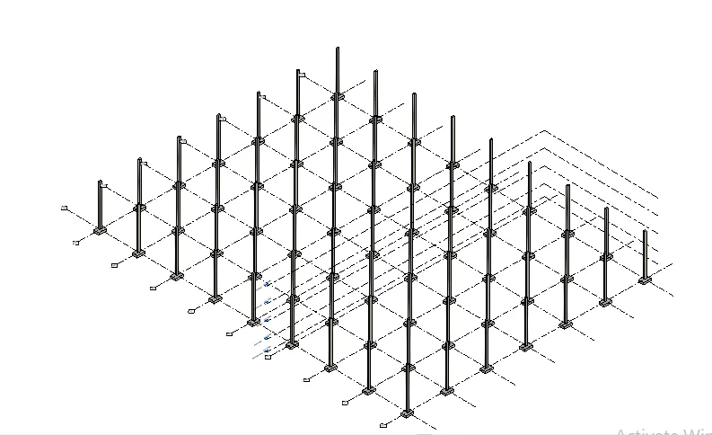
3d view of column
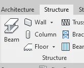
for draw the beem go structure tab and go to beem
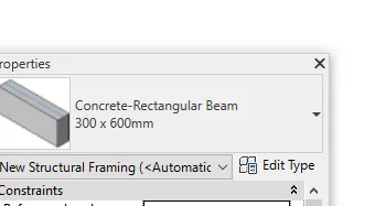
select the beam in the property browser
then drag all the column in the ground floor and click finish
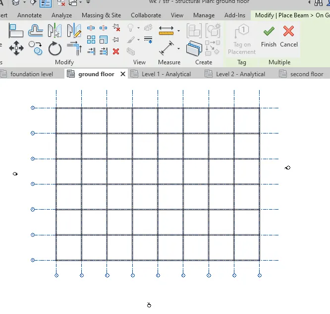
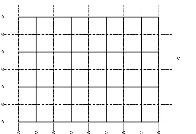
similarly beems draw in all the level
first floor beems
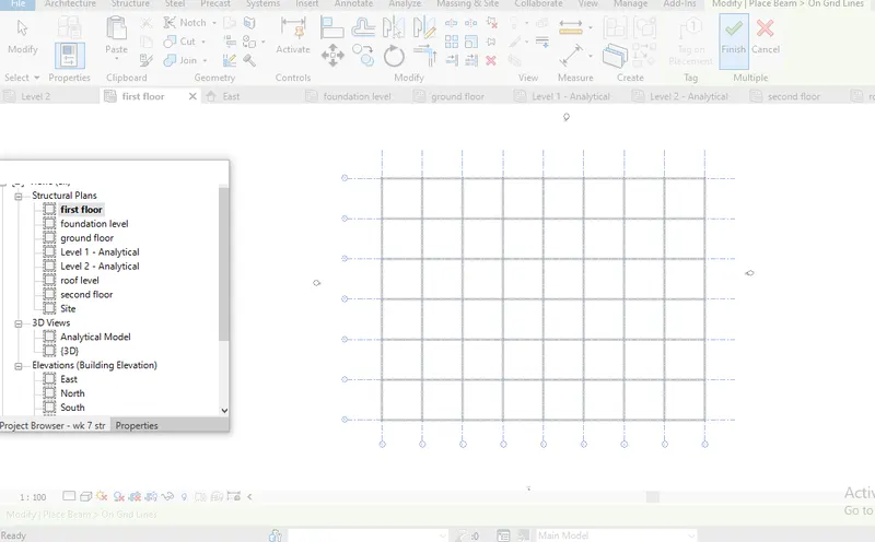
2nd floor beems
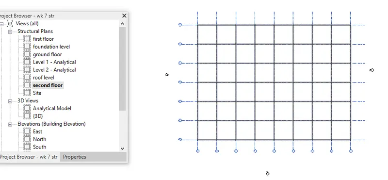
3d view of beems in all the level
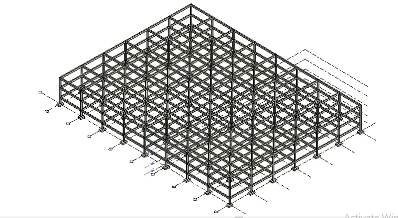
similarly floors created in all the level.
first floor created in ground floor for that select ground floor and click architecture floor select a rectanglr and selet the boundary
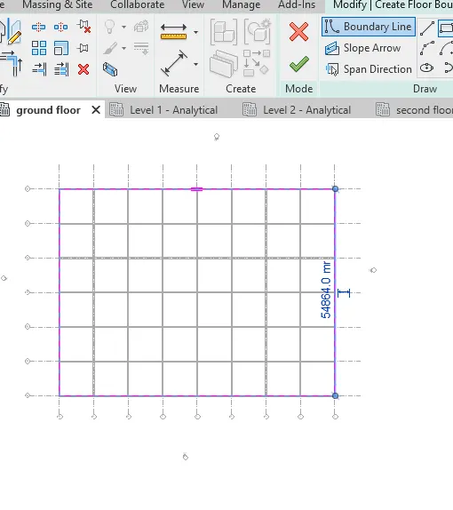
then click the tic marc
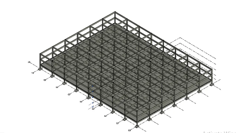
the same step is repeeted in all the level for floor creation
floor created up to second floor
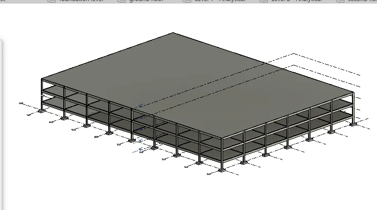
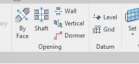
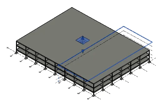
providing the openings for escalator or stair by click architectur < shaft opening<enter
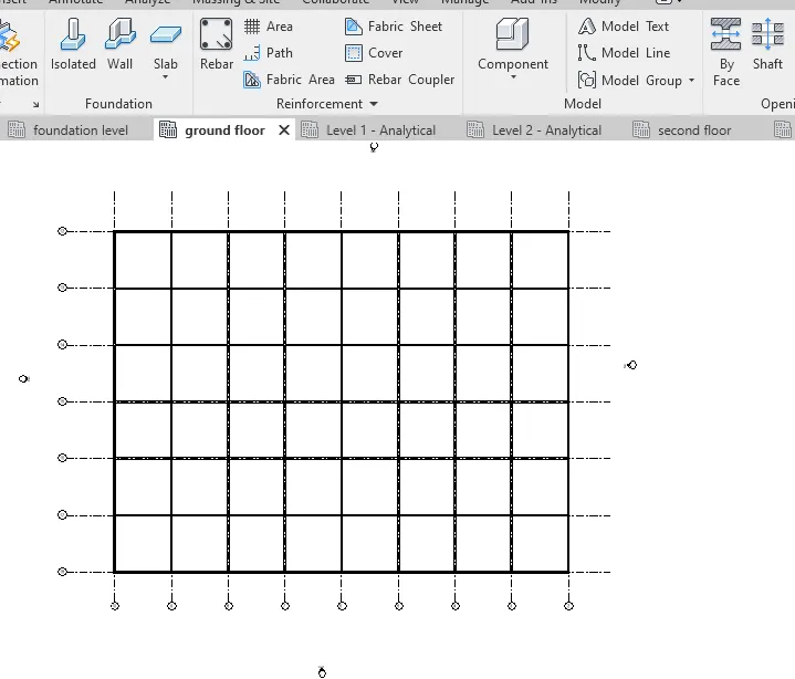
shaft opening created in one level leads to all the levels
RESULT
All the given components created
4.
AIM
To include the following components in an architectural model:
a. Wall Layout with appropriate material and finishing
b. Exterior façade with fancy finish
c. Interior partition walls to size rooms
d. Components to add details to a room ( Desk, Chair, Lighting, Plumbing fixtures)
e. Add components such as stairs Elevators
f. Have at-least one side of the building with curtain walls and glass panels
g. Include interior and exterior lighting fixtures
h. Place proper topographic components from outside ( Trees, Parking, Plants) to add details to the model.
PROCEDURE
- Initially, we have to link the architectural and structural template.
- For this, first open architectural template
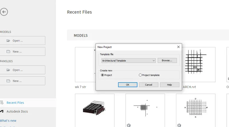
- Open the structural template collaborate and synchronise with the central by the structural model before link with architectural
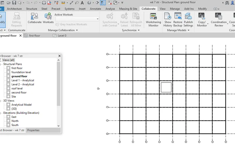
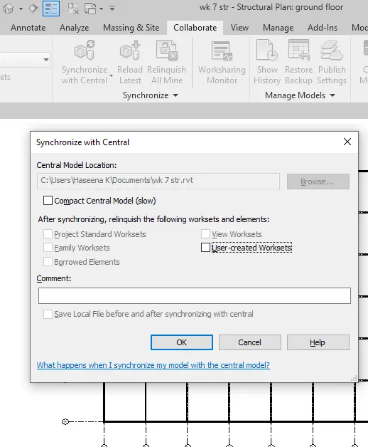
- then the structural template linked with architectral
- For this, open architectural template go to insert tab --> revit links --> choose the links.

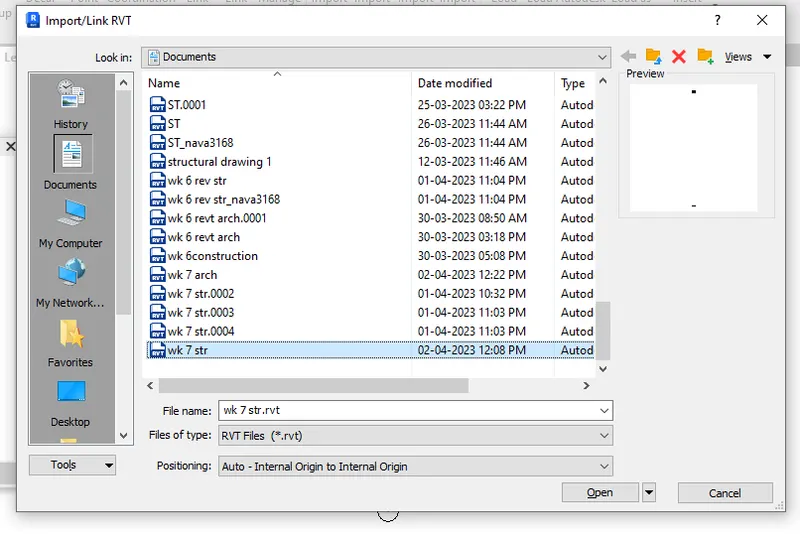
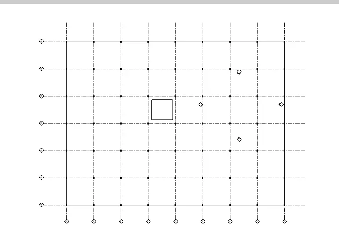
- Now, using the copy/monitor option we have to copy these elements to structural template.
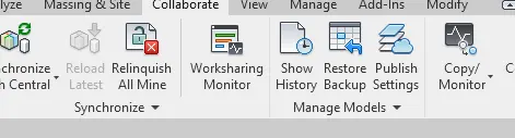
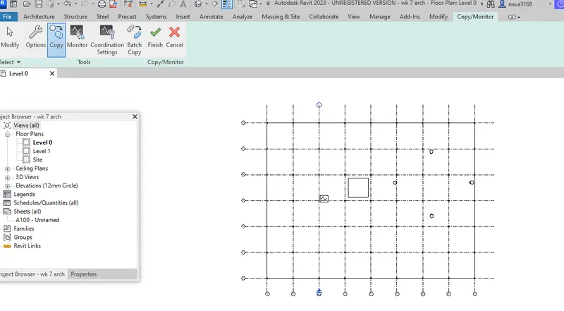
after copying the grids and levels we have to copy columns and floors
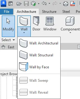
Then create walls for that go to architecture select walls
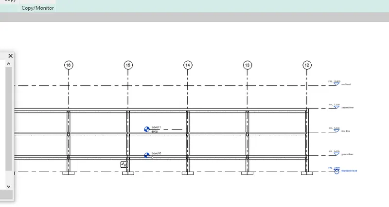
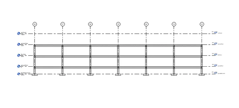
- after copying the grids and levels we have to copy columns and floors
- Then create walls for that go to architecture select walls
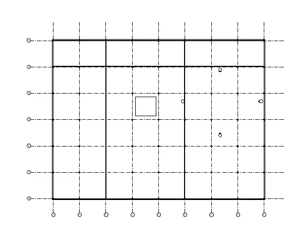
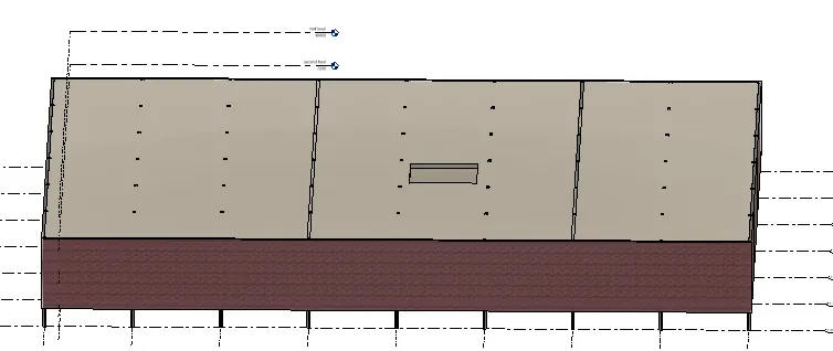
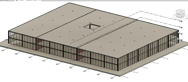
- 3D VIEW OF WALL CREATION
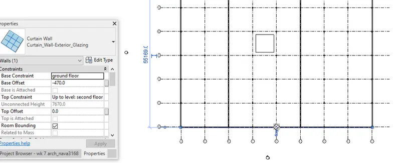
- Select the front wall as glass wall
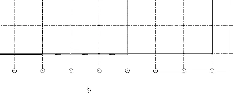
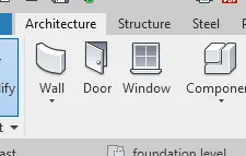
- select doors from architectur tab
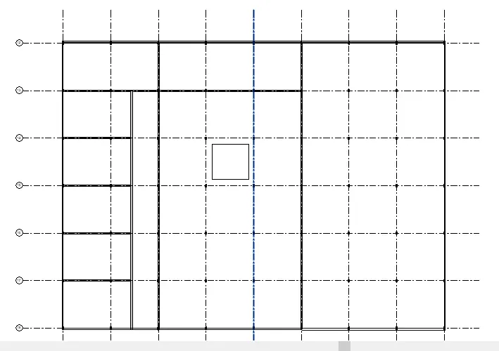
- devide the office for cab area with partition wall.for that go to architecture wall.
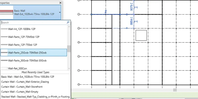
- select the wall interior wall as partition wall by go to property and change wall type
-
after completing it isert doors remaining portions for we wanted.for that go to architecture < door <(for more different type door if we wanted go to load family and load varies type of doors)
insert the door for meeting hall
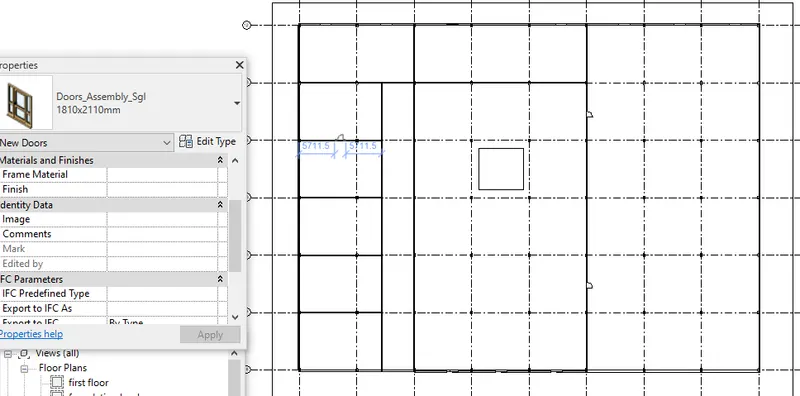
then insert the cabin doors after placing all the doors in the ground floor copy the doors to the first floor by select the door copy and paste to aligned levels
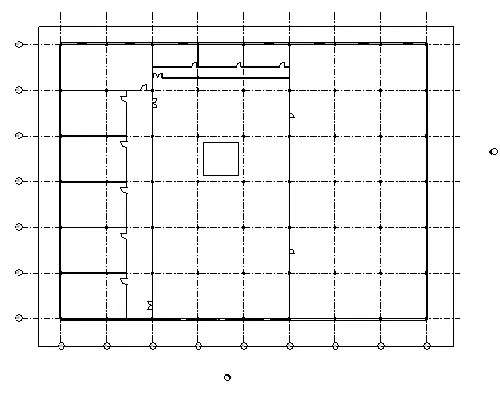
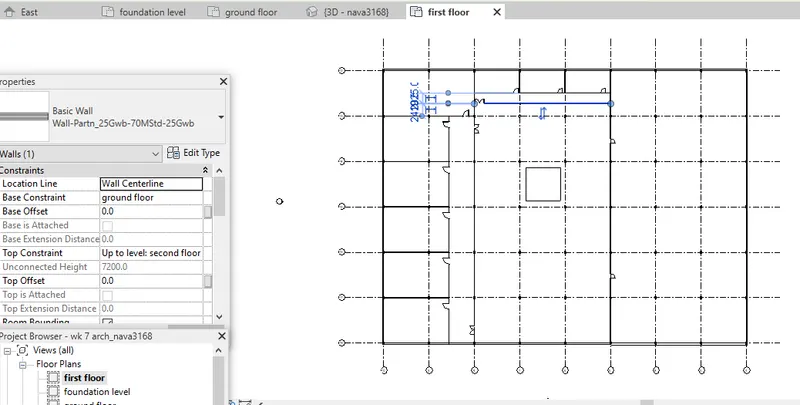
after completing the doors insertion insert stair.for that go to architecture select stair
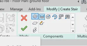
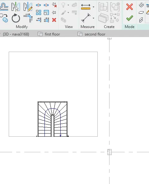
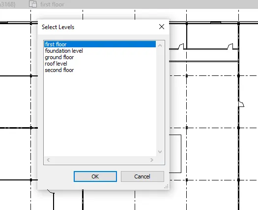
after insert the stair in ground level stair inser in to first level for that select stair then select select levels go to elevation view click first floor
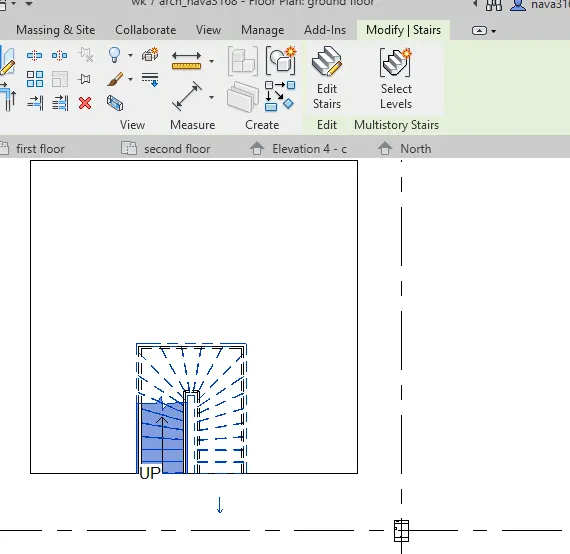
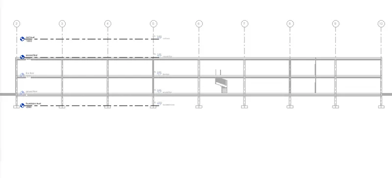

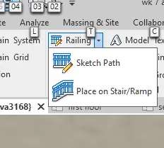
Then insert railing for that go to architectaral tab go to railing select the path for railing
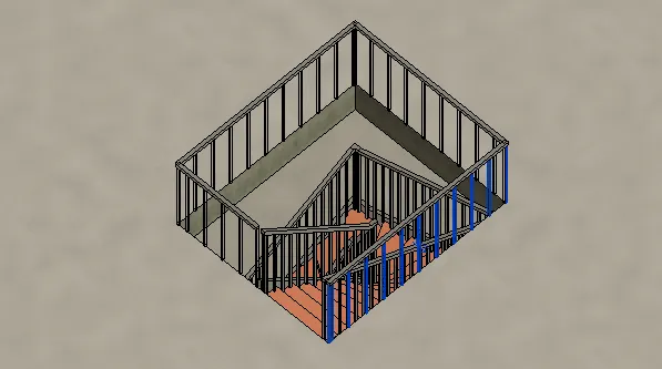
Then draw stair room in second floor using wall
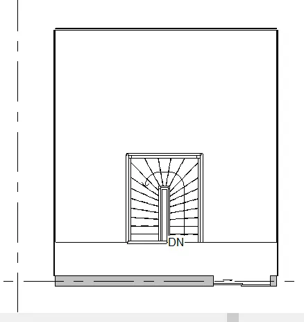
3D view of stair room
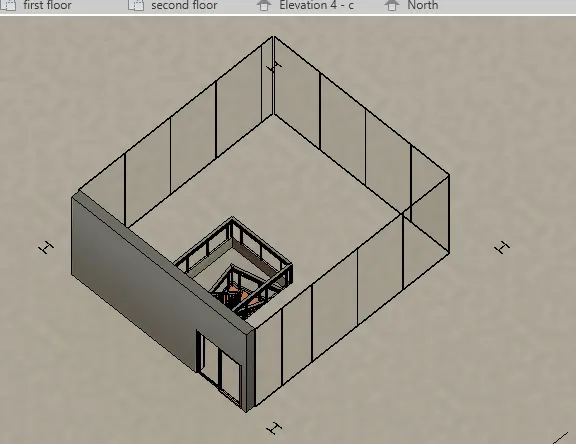
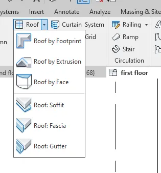
insert roof to the stair room for that go to architecture select roof and select boundary
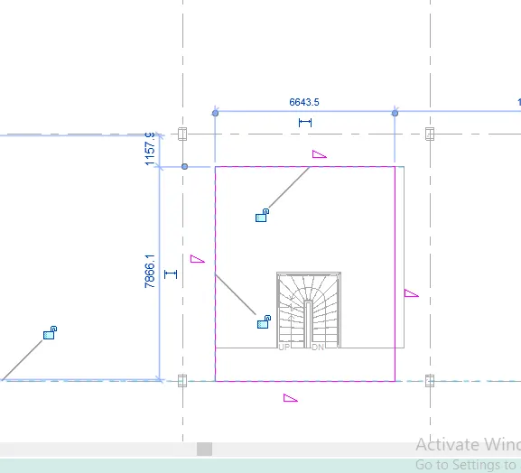
- 3d view
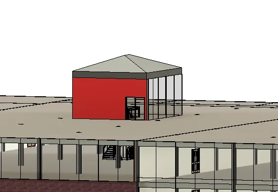
- a) Wall layout has been developed. Wall thickness provided is 200mm. Now, we have to assign the material to the wall. Here, wall is availbale only in the one third portion rest is provided as curtain wall. Hence, wall material is needed to be assigned only at back portion.
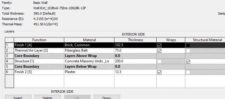
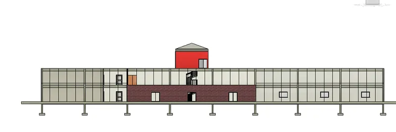
-
b) Exterior facade with fancy finish is also provided.
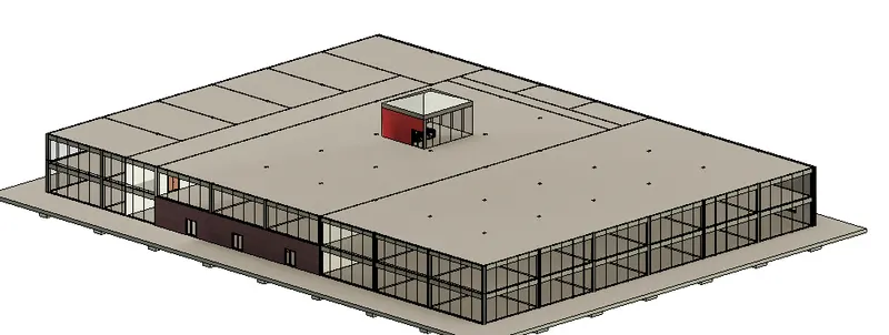
c) Interior partition walls to size rooms. Wall thickness provided is 138mm
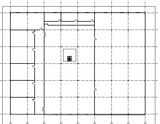
d) Components are to be added to add details to a room
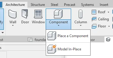
select load family and load varies components
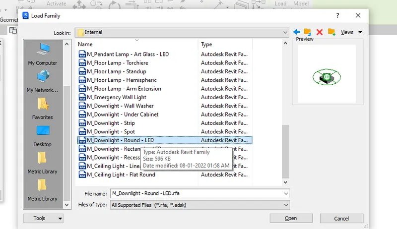
from light family varies lights selected
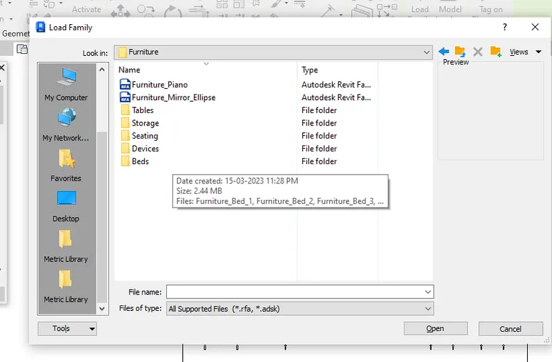
from furnitur family varies furnitures selected
similarly from plumbing family pipe urinals water closets selected
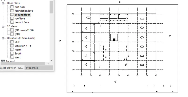
after complete the coponents in groundt floor which copied to first floor
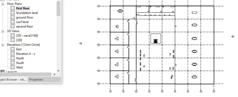
e) Elevators and stairs have also been added to the plan: Stairs surrounding the elevator is included.
f) The front, east and west portion has been provided with storefront curtain wall.
g) Interior and exterior lighting fixtures:
Street lights and parking space have been provided.
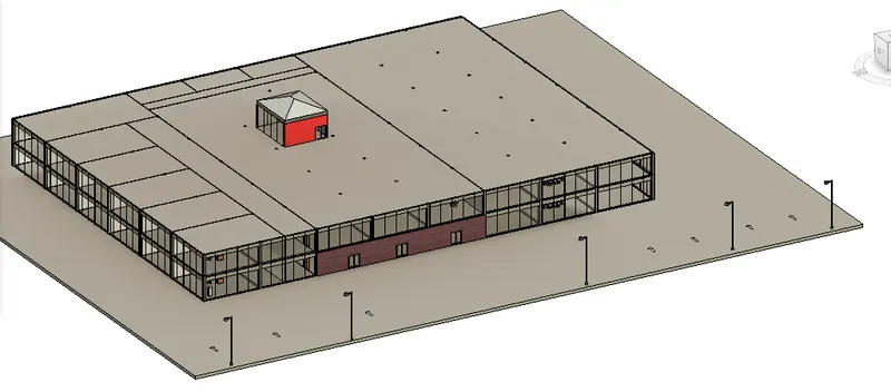
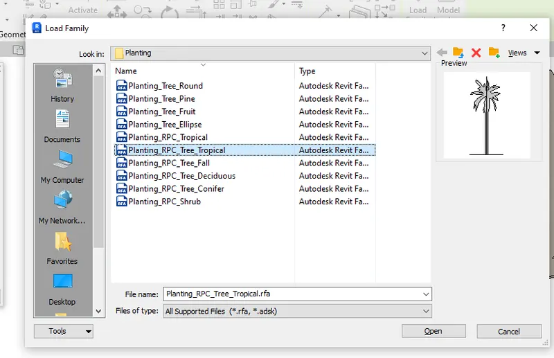
h) Now, other topographic components needed to be added:
For this, go to Architexture tab --> components --> load family --> select plantings and place shrubs and other plants.
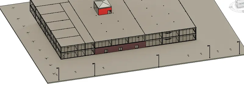
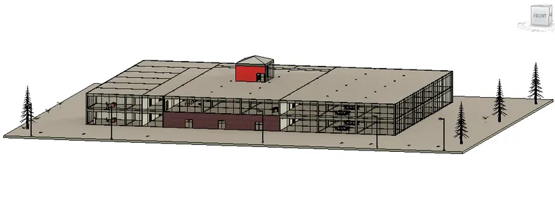
Result:
- All the architectural components have been placed including parking area and geographic components like plants.
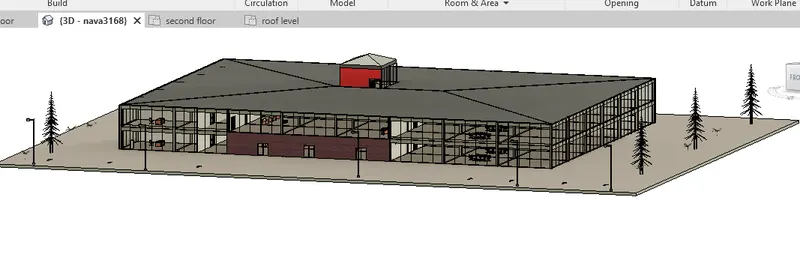
5) Provide a set of drawings in an architectural and structural model to list the following details with categories and appropriate sheet templates included
a. Floor Plans with Annotations
b. Elevations
c. Sections
Aim:
To provide the following in sheet templates:
a. Floor Plans with Annotations
b. Elevations
c. Sections
Procedure:
a)
- Initially, provide the annotations to each level.
GROUND LEVEL
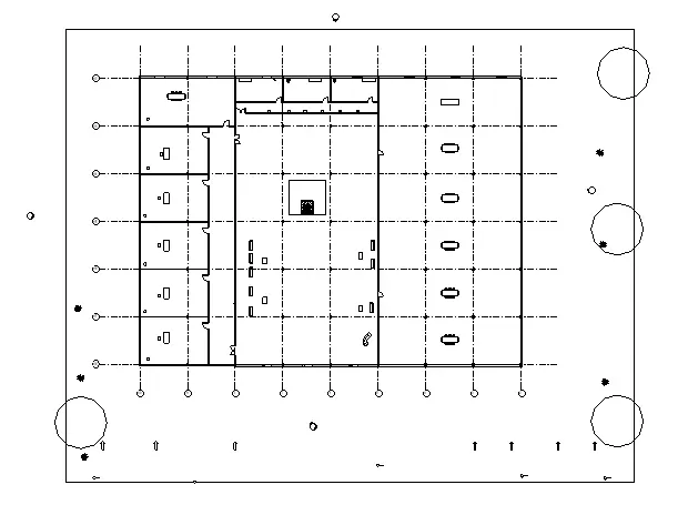
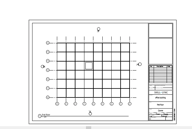
FIRST FLOOR
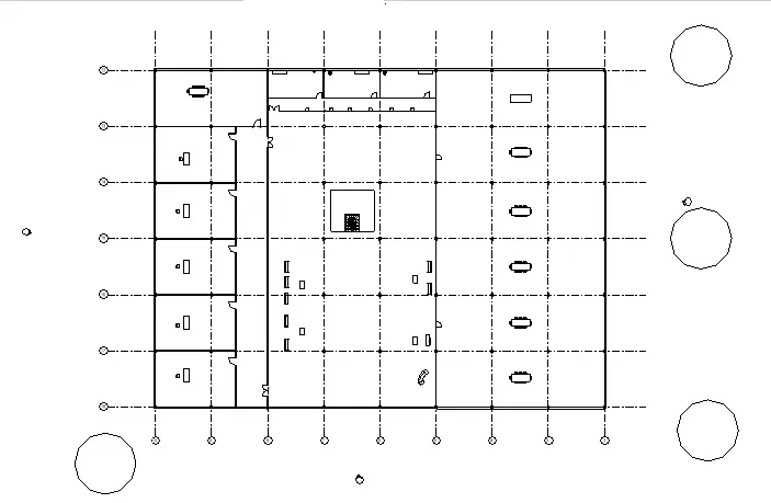
SECOND FLOOR
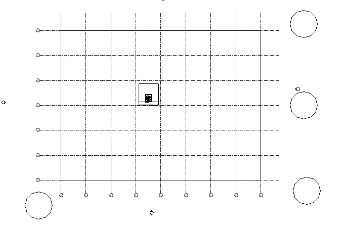
ROOF LEVEL
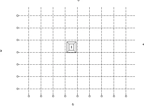
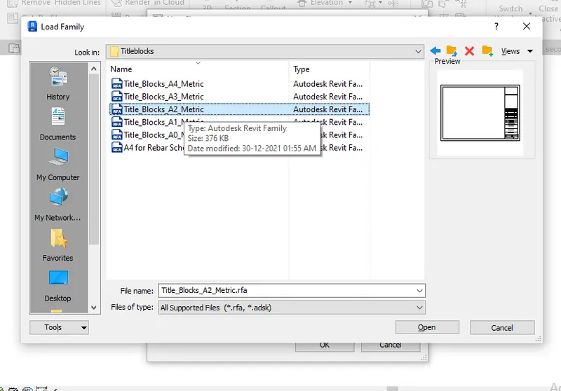
Place these are in sheet template for that go to view tab select sheet
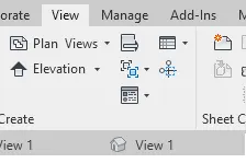
select A2 metric
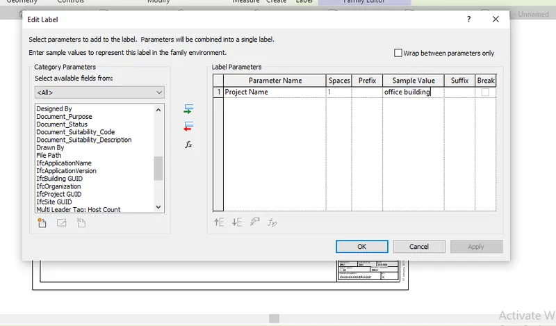
give project name as office building
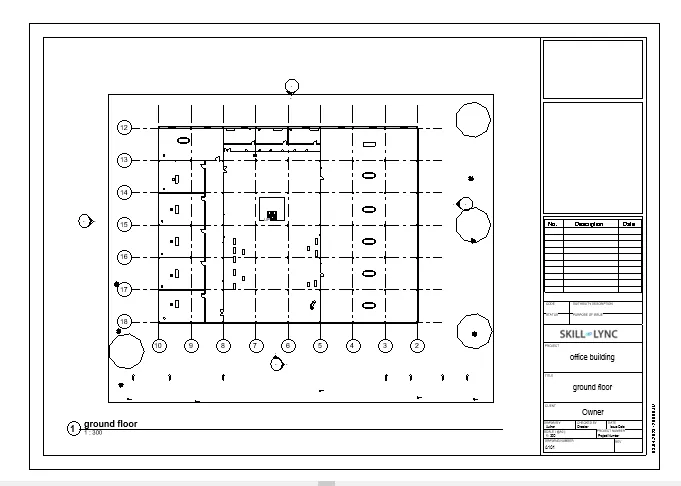
after sheet created drag ground floor to the sheet with proper scale
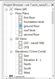
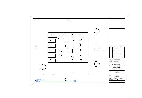
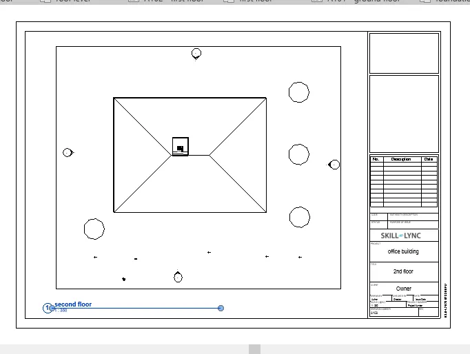
similarly first floor second floor and roof level is created in sheet template for that in project properties all the views there open the sheet and drag the corresponding plan to the sheet
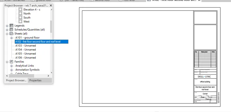
first floor sheet template
second floor sheet
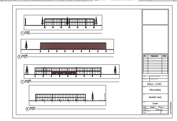
elevation views
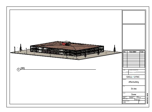
3d view
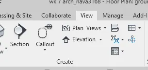
section cut for that select ground floor go to view section then select section line
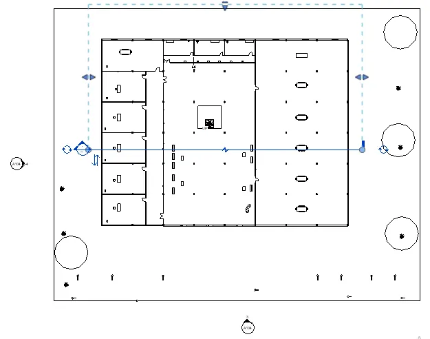
then go to ptoperties click section
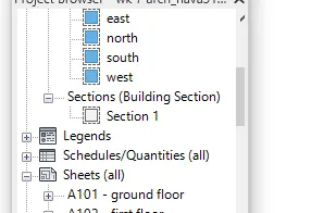
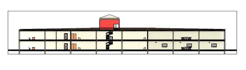
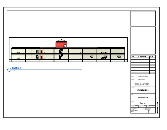
these section view isdrawn in a sheet
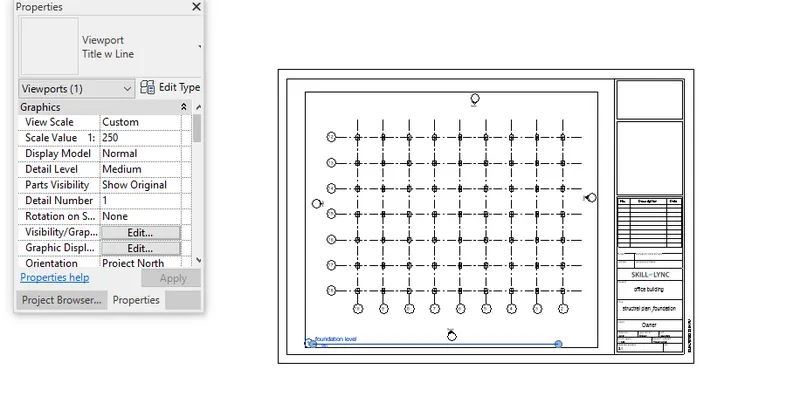
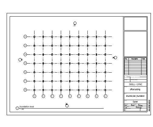
structural template open and structural plan drag in to the sheet
foundation level
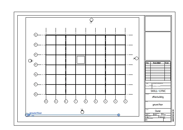
ground floor
first floor
RESULT
ALL THE SHEETS CREATED
Q6)
AIM:
Using the Rendering settings, Render images of the 3D model produced and include the rendered images to the drawing sheets
a. Rendering from interior rooms
b. Rendering from out showing topographic features
c. Rendering through structural framing.
PROCEDURE
Before rendering first set the camera views for that click view select camera and place the camera in various rooms
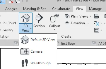
after create the views select view and go to view click on render
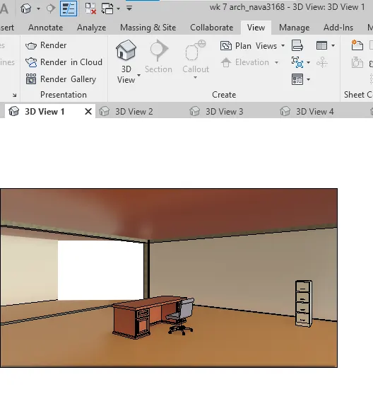
set mediam interior sun and artificial lighting then render view
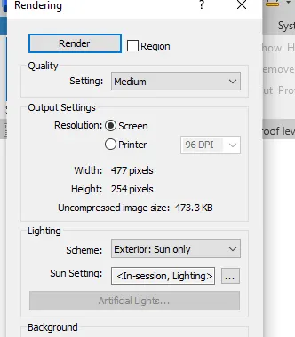
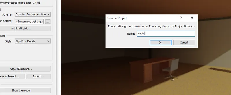
after rendering save the project as cabin
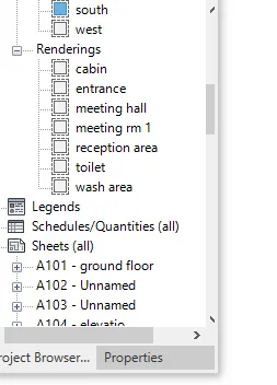
rendering images created are display in project browser
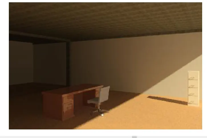
rendering image of cabin
rendering image of entrance hall
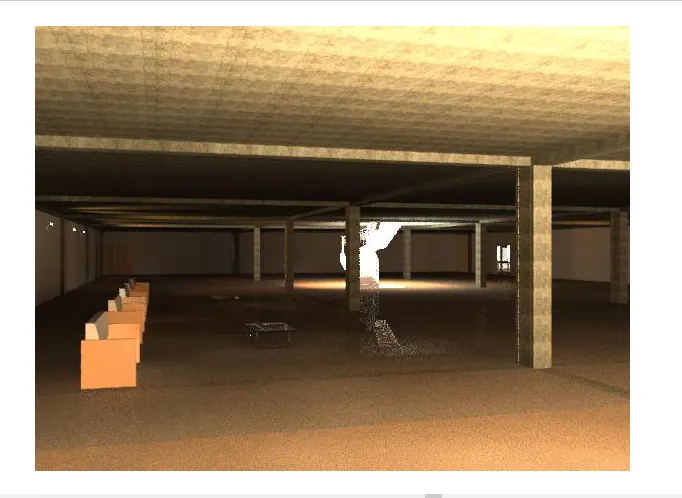
rendering image of meeting hall
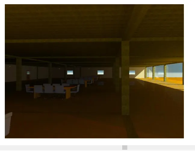
rendering image of meeting hall
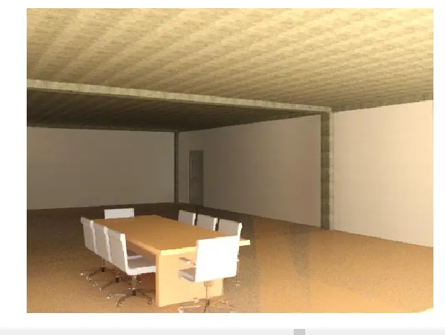
rendering image of reception area
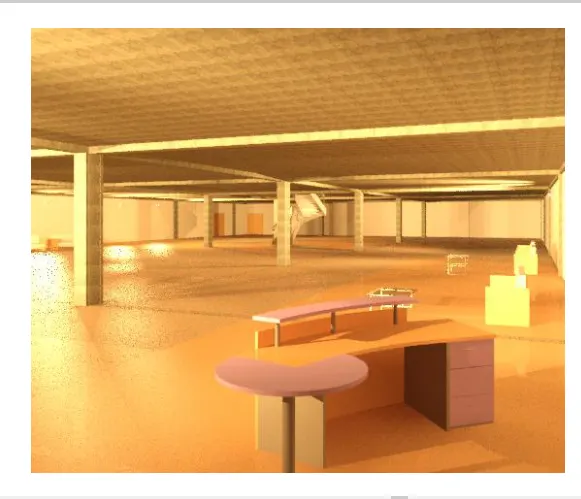
rendering image of toilet
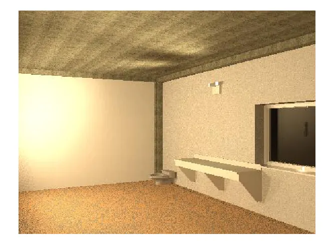
rendering image of wash area
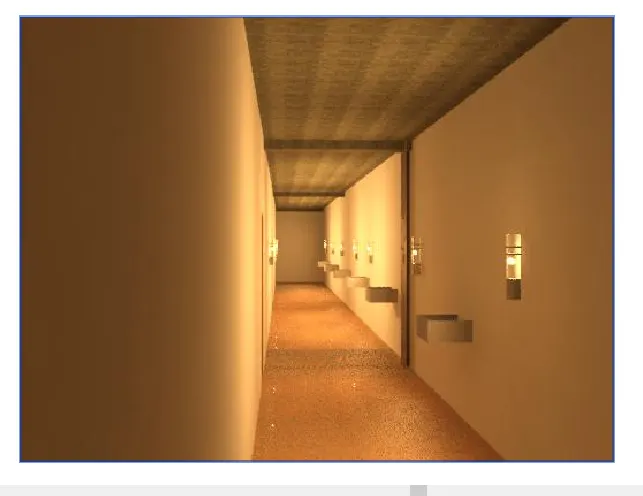
rendering image of office building
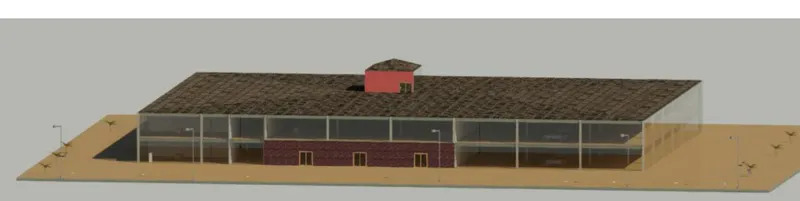
create sheet and drag the rendering image in to the sheet
select A2 metric sheet
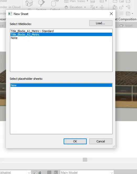
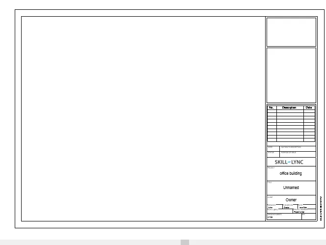
drag the images in to the sheet
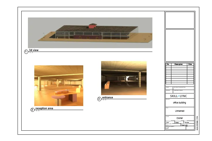
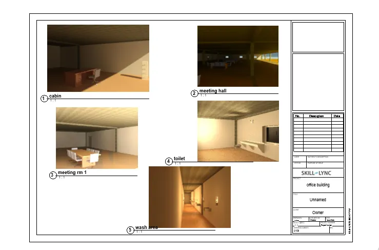
RESULT
THE VARIES VIEWS ARE RENTERED AND WHICH DRAG IN TO THE SHEET