Creating Architectural and Structural model with 3D rendering using REVIT
1. Select the type of Structure you want -
i) As there are 3 options - a) Multi-Unit Residential Apartment
b) Office Buildings
c) School
ii) So , I'm going to consider Office Building for this Project 2.
2. Assumptios for the Office Building as per NBC:-
i) Location of the Project - Mumbai City
ii) It's in terrain 2 ( i.e plain area )
iii) Type of Building - Commerecial Type
iv) Width of the street is = 50 feet ( 15.24m)
v) Height of Building is = 45 feet ( 13.7 m)
Therefore as per NBC , The height of building should not exceed 1.5 times of width of building.
vi) As it is Commerecial type structure , a safety or fire exit must be provided in structure.
3. Aim - To include the following components in the Office building.
a) Foundation – Isolated / Wall/Matt Foundation
b) Columns
c) Beams Connected to Columns
d) Roof Framing/ Truss
e) Floor / Decks
f) Floor Openings for Elevators and Stairs
Introduction:-
- A Commercial type structure includes Office builidings, hotels, malls, warehouse etc.
- To build any type of construction following compomnents are necessary.
- Foundation - Without foundation structure cannnot build. Foundation is necessary to transfer the load of building from footing to soil in uniform manner.
- Columns - Columns is a vertical member to carry vertically Axial load . Columns transfer the to the footing.
- Beams - Beams are horizontal member and it resists the load applied laterally to the beams axis.
- Roof / Truss - A roof is the topmost componenets which are build to cover the building. It is supported on the walls of the buildings.
- Floor / Deck - A floor system are designed using a system of beams that connects to the walls. It is a lower surface of the room or It is a base level of a room.
Procedure:-
Step
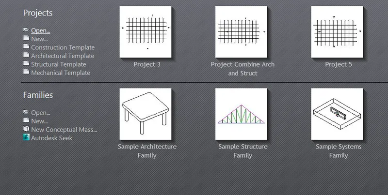
i) Open the Week 6 challenge file in which we have created a Structural file.
ii) Open the Project 5 file.
Step 2
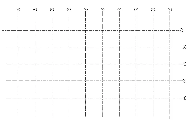
i) Grids are already created in X and Y direction
ii) In X direction - 20'
iii) In Y direction - 20'
Step 3
i) Click on East Elevation view
ii) Increase the Level and Rename it as GF, First Floor Level, Seconds Floor Level, Third Floor level and Roof Level
iii) Set a distance of 20' between the levels and roof level is 15' above the Third floor level
iv) Create an Foundation Level at a distance of -10'
Step 4
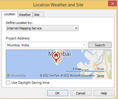
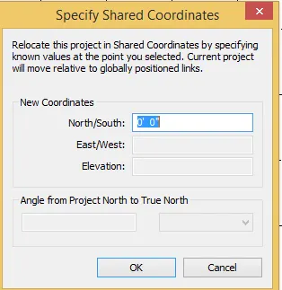
i) Set the Project location - Mumbai India
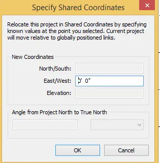
ii) Set the Project Coordinate as 0'0" in North South view and 0'0" in East West View .
Step 5
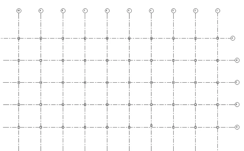
i) Once the parameters are set, Now we have to draw the column.
ii) Select Column from the Structural Tab
iii) Draw the columns by using At Grids option.
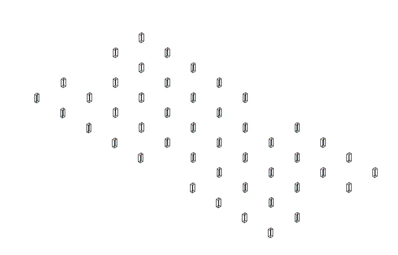
3D view of Columns at Ground Floor
Step 6
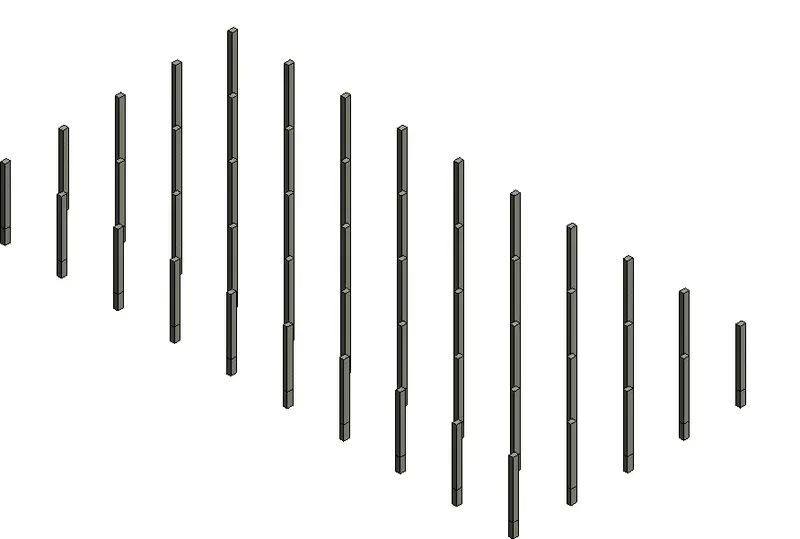
i) Now we have to take this column at First Floor
ii) So select the Columnn and Make the top level as First Floor level,
Step 7
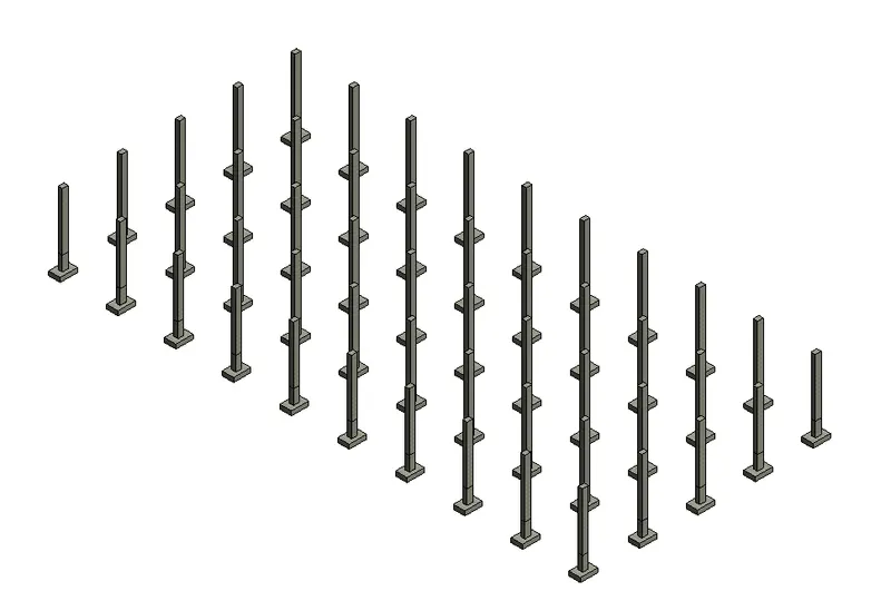
i) Now we have to add the Footings to the column.
ii) As we have considering Individual footing for each column
iii) So Select - Structural - Isolated Footing
iv) At Foundation level Select the grids and assign Footing to individual column
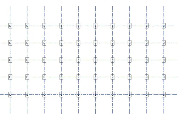
3D view
Step 8
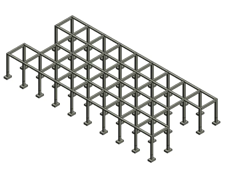
i) Now we have to add the beams to connect the columns
ii) Select - Structural - Beams and connects the beams
iii) Draw the beams at first floor
iv) Select size of beam 12 x 24
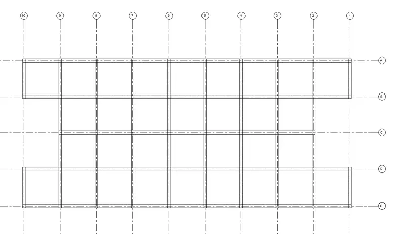
3D view of beams
Step 9
i) Now we have to assign the Floor to ground floor
ii) Select the floor and draw the boundary as per your plan
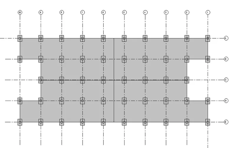
3D view
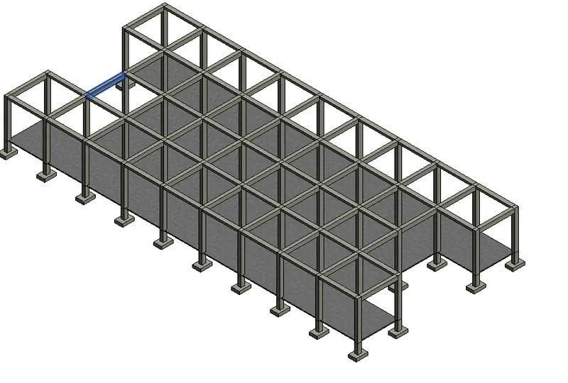
Step 10
i) now we have to design 1st 2nd 3rd floor same as the Ground Floor
ii) Select the Gf and copy to and Paste it to Aligned selected levels.
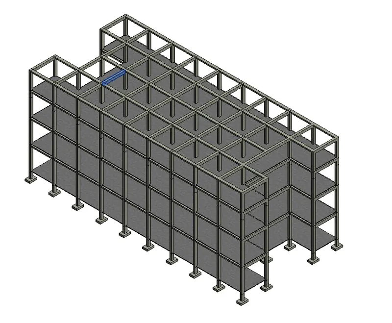
Step 11
i) Draw the Bracing at the top to gives stability to the structures
ii) Select Bracing and assign it at the top.
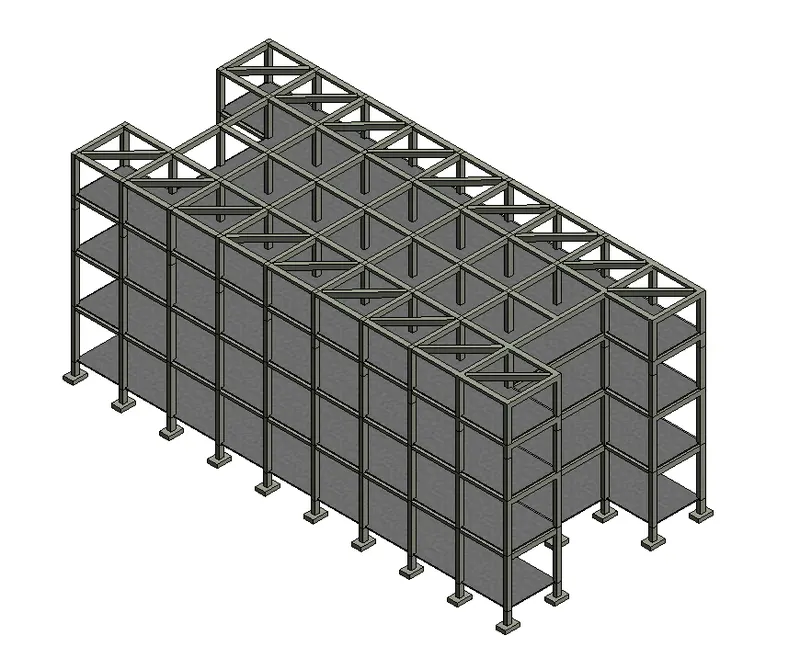
Results - All the structural Components are added to the structure
i) Column
ii) Footing
iii) Beam
iv) Floors
v) Bracing
4. Aim:- To Using the architectural model, include the components to the structure.
Procedure-
Step 1)
i) As we already created a Architectural file
ii) Add the links to the Architectural Model by using Manage link
iii) Then using copy monitor opting copy the elements to the Architectural model.
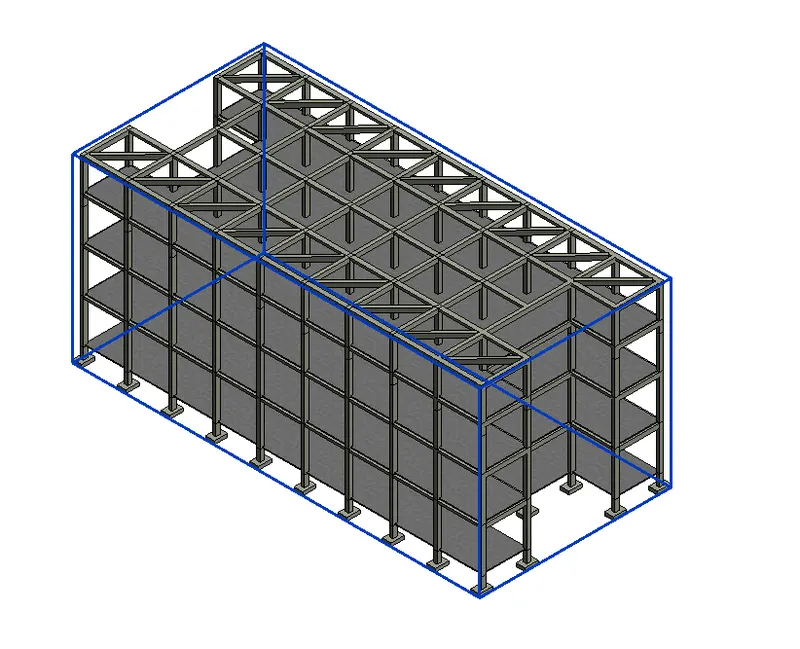
Step 2
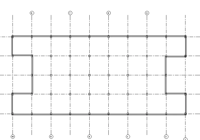
i) Now we have to add walls to the structures
ii) Click on Wall
iii) Select Generic 8" walll
iv) Draw the walls slecting the exterior part
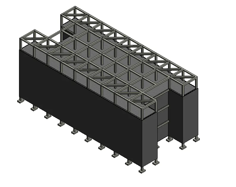
v) Now we have to take this wall at remaining levels
vi) Select the walls - Make the Base Constraint - Ground Floor and Top Consttraints - Third Floor level
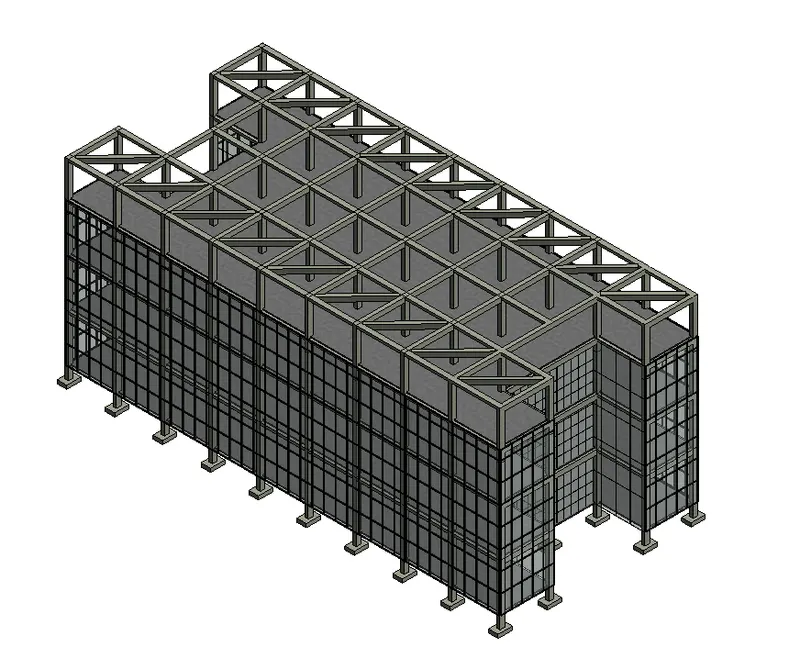
vii) Now Select the wall matrial as curtain wall / storefront
Step 3
i) Draw the partition walls to the structure to show the work station to the office builing
ii) Follow this for remaining levels too
iii) Draw the Shafts at the center to show the lift area.
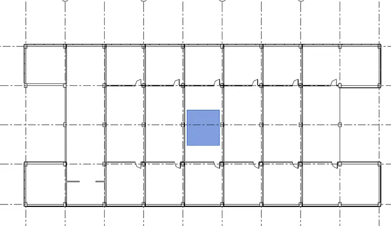
Step 4 )
i) To add the components such as desk, chairs, lighting fixtures, plumbing fixtures etc
ii) Click on Insert
iii) Load family and load the component into the plan.
1) Components at Ground floor
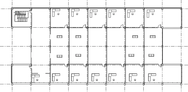
2) Components at First Floor
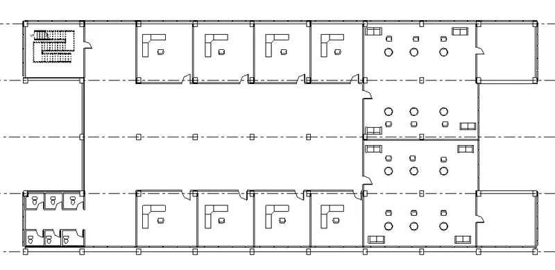
3) Component at Third Floor
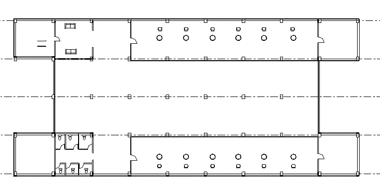
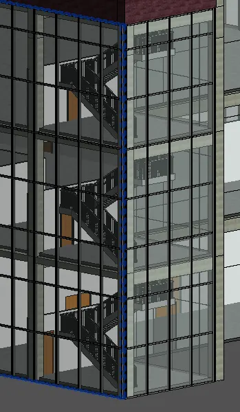
4) Staircase -
5) Lighting Fixtures and Planting component
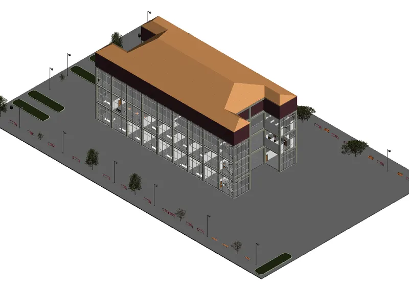
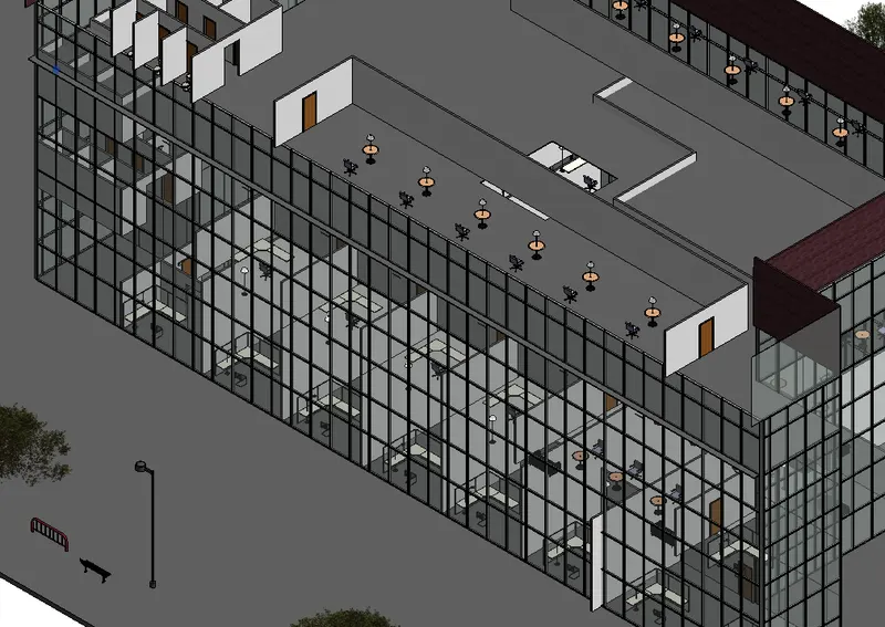
Results- All the Architecture Components are added to the Office Building .
1) Components at Ground Floor, 1st Floor, 2nd Floor, 3rd Floor
2) Staircase
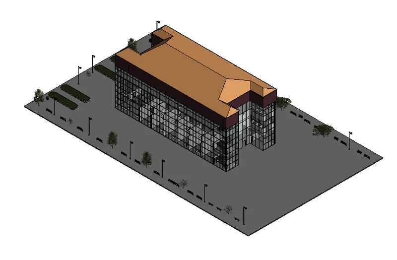
3) Topographical view
5. Aim:- To Provide a set of drawings in an architectural and structural model to list the following details with categories and appropriate sheet templates included.
Procedure-
Step 1
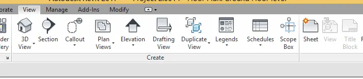
i) Open the Project file
ii) Click on View tab
iii) Click on Sheet tab
Step 2)
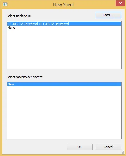
i) Once you Click Sheet , Following Dialog box will open
ii) Click on Load Family
iii) Click on Title Block and
iv) Click E1 30 x 42 title Sheet
v) Click on Okay.
Step 3
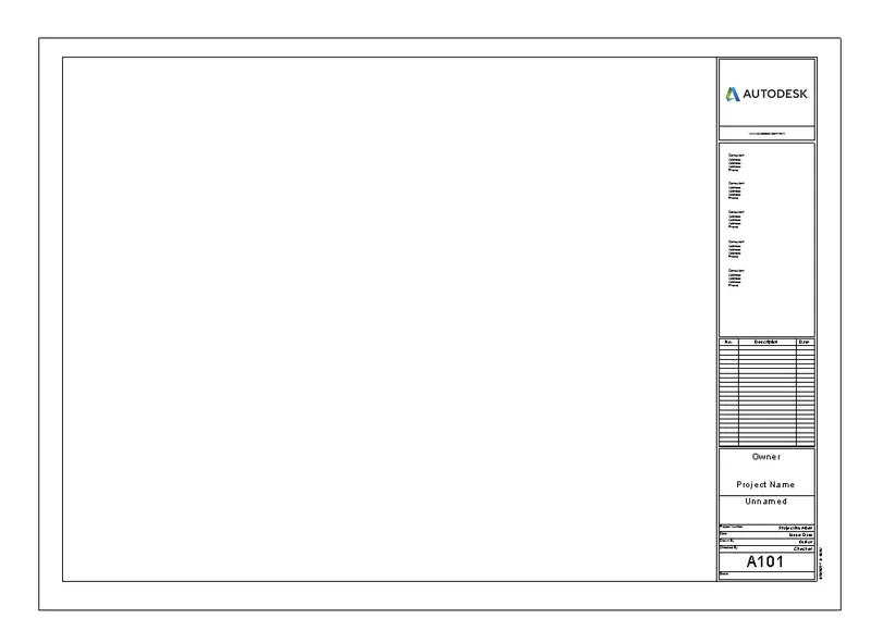
i) After Clicking okay
ii) Sheet will be created in Modal Space
A) Architectural Model -
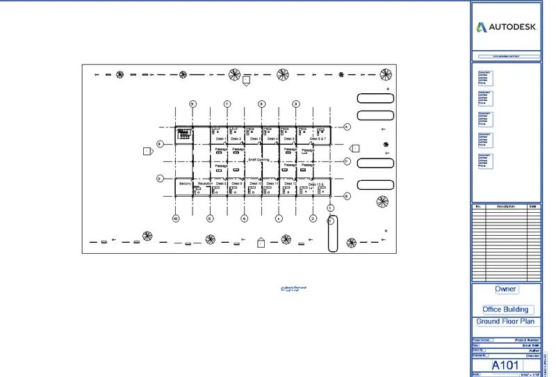
1) Ground Floor plan
i) Sheet No - A101
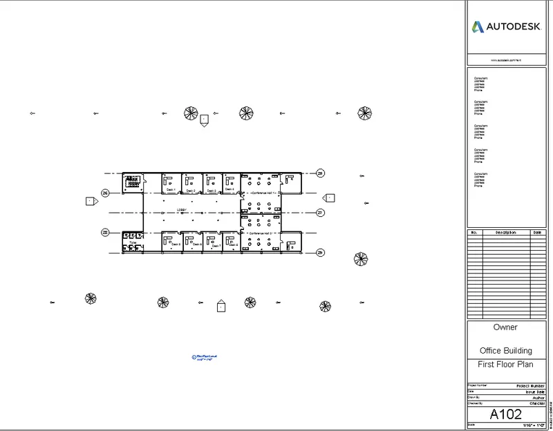
2) First Floor Plan -
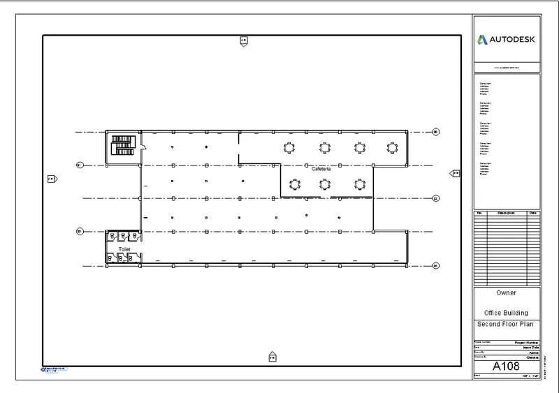
3) Second Floor plan
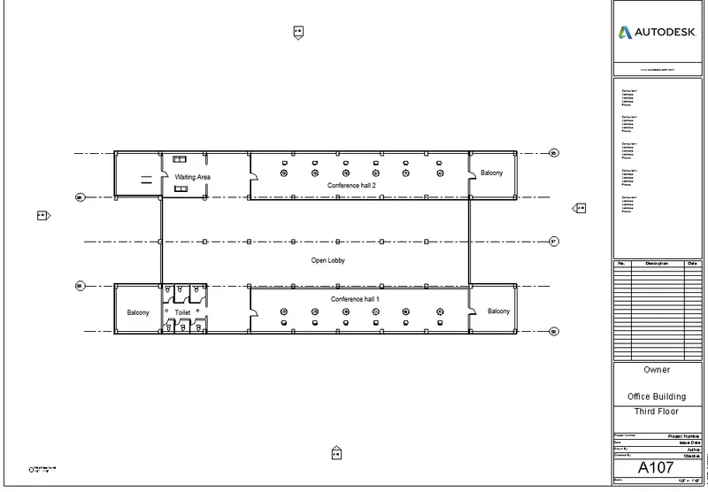
4) Third Floor -
B) Elevation Views-
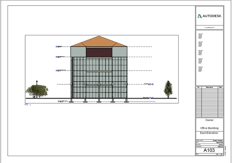
1) East Elevation
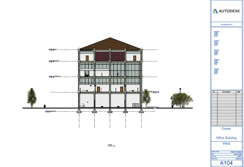
2) West Elevation -
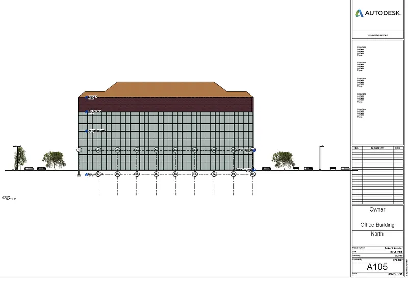
3) North Elevation -
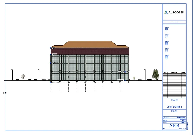
4) South View
B) Structural Floor Plan -
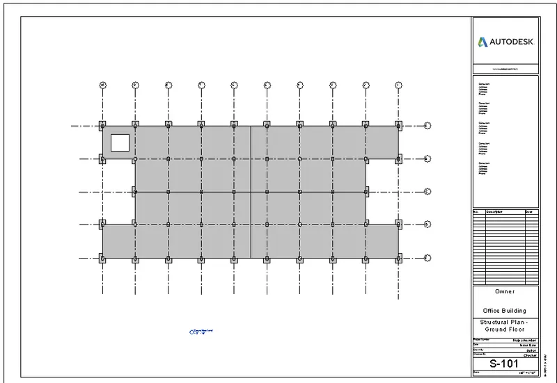
1) Ground Floor plan -
2) 1st Floor Plan -
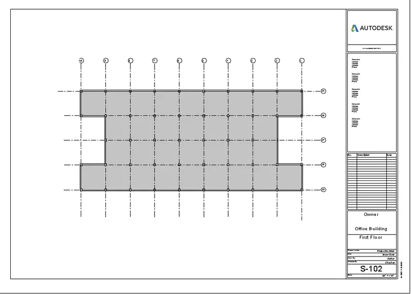
3) 2nd Floor Plan -
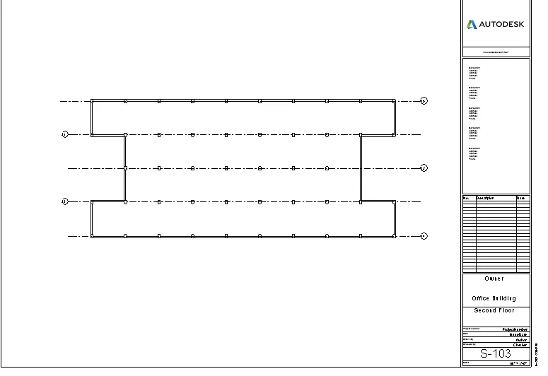
3) 3rd Floor Plan
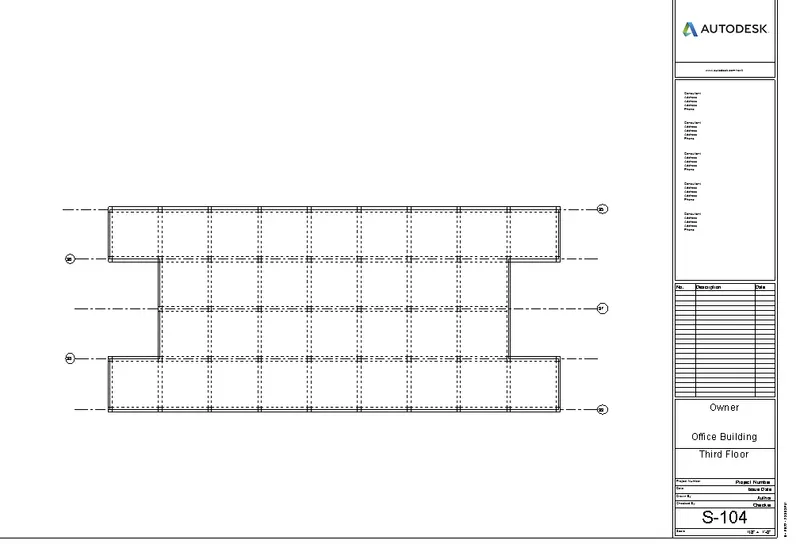
4) Roof Level
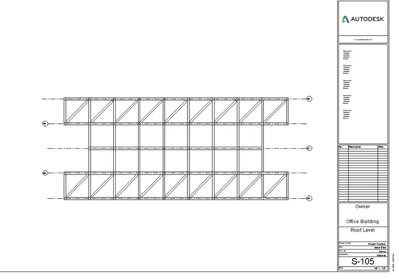
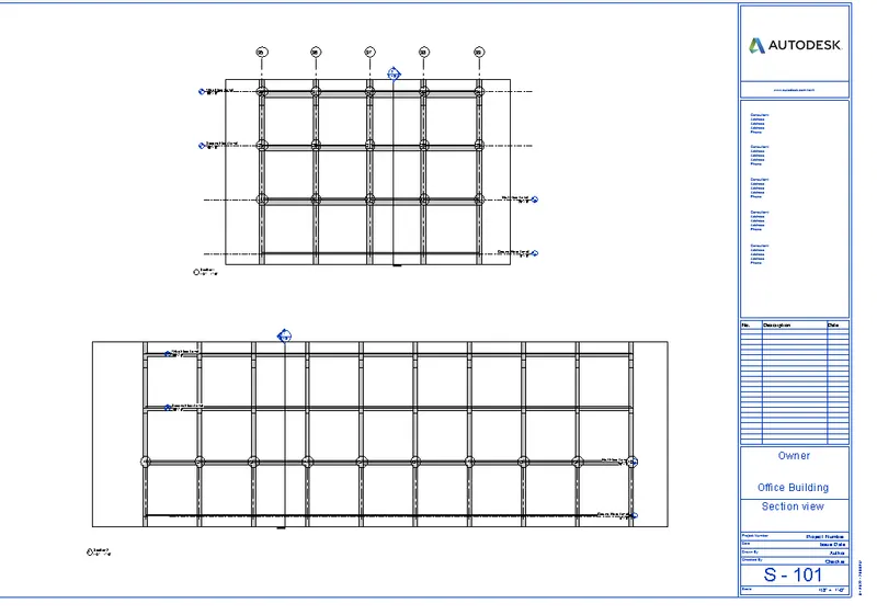
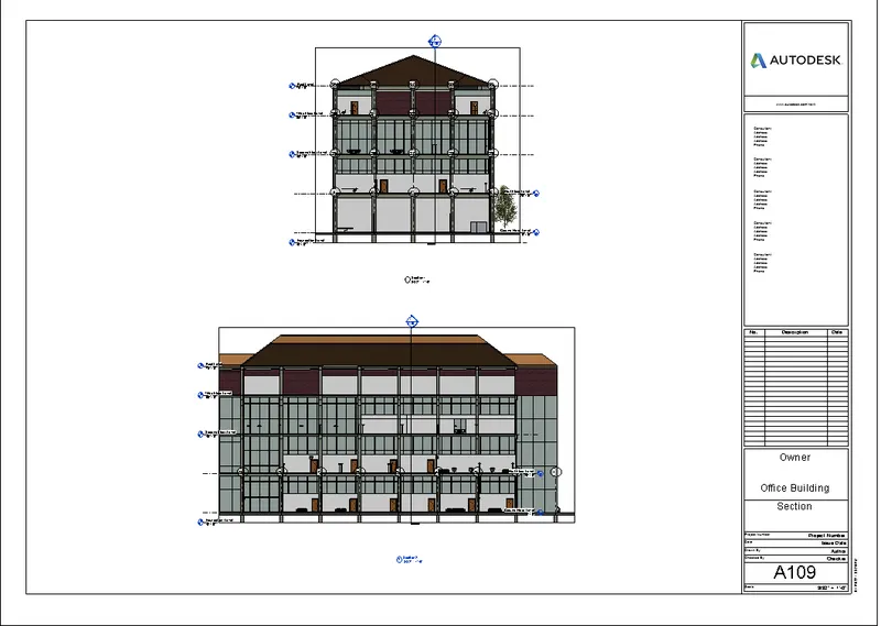
C) Section view -
1) For Structural plan -
2) For Architectural plan -
Results - All the views are creted in respective sheet templates .
1) Floor Plans - Ground Floor plan
2) First Floor Plan -
3) Second Floor plan
4) Third Floor -
B) Elevation Views-
1) East Elevation
2) West Elevation -
3) North Elevation -
4) South View
B) Structural Floor Plan -
1) Ground Floor plan -
2) 1st Floor Plan -
3) 2nd Floor Plan -
3) 3rd Floor Plan
4) Roof Level
C) Section view -
1) For Structural plan -
2) For Architectural plan -
6. Aim - To using the Rendering settings, Render images of the 3D model produced and include the rendered images to the drawing sheets.
Procedure-
Step 1
i) To show the rendering view , we have to place the cameras at respective room
ii) Click on Camera and place it on respective rooms
iii) Create a 3D views of the rooms
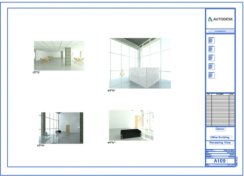
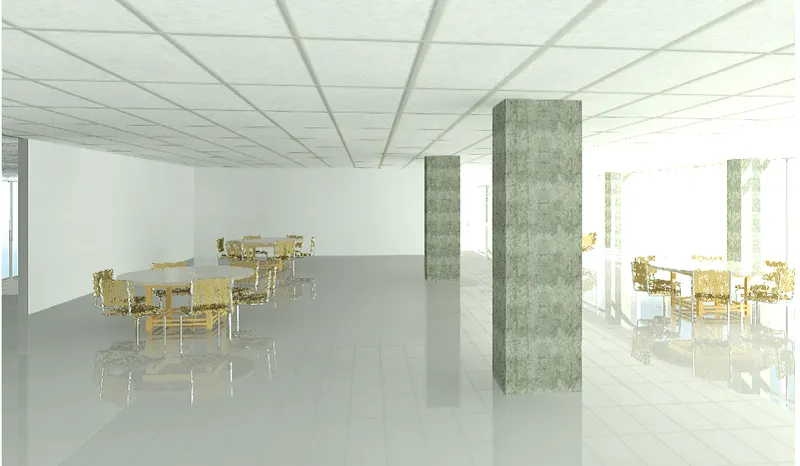
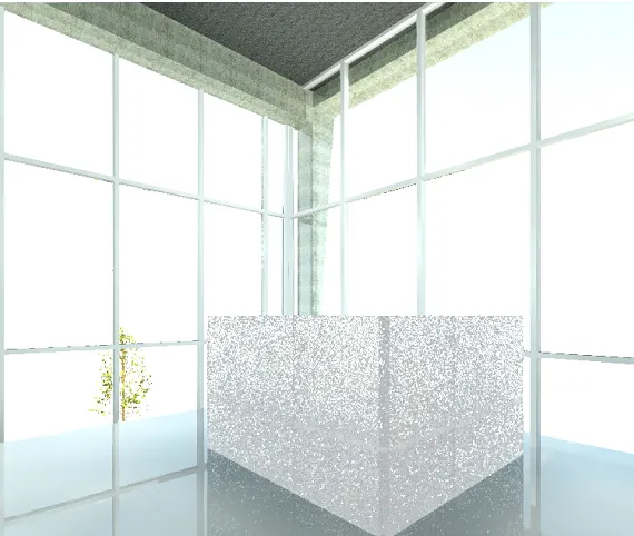
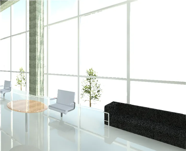
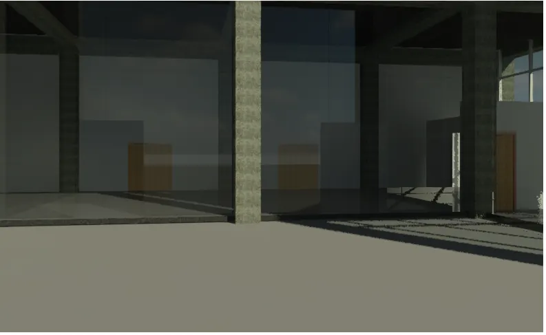
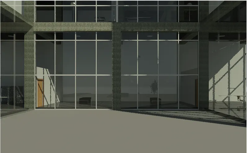
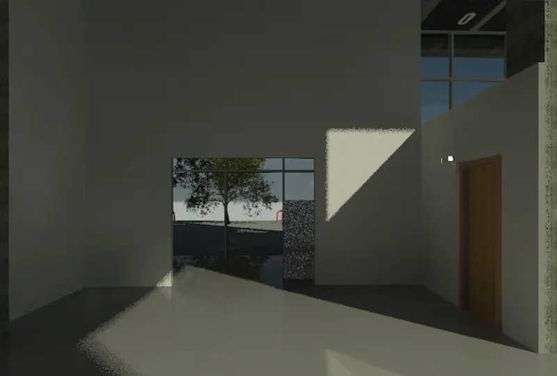
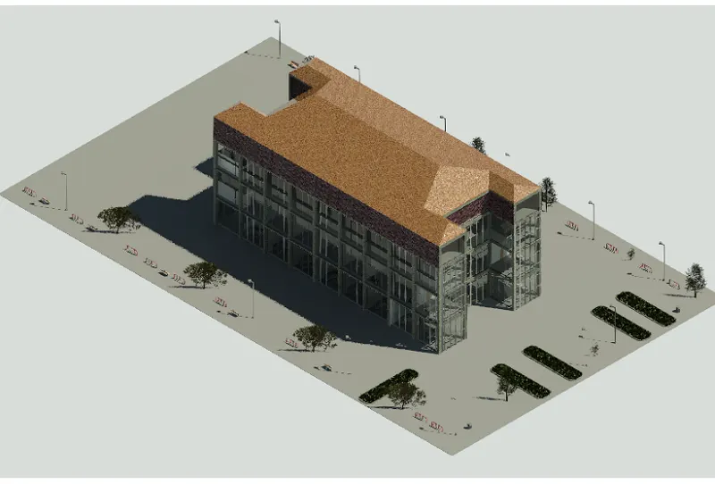
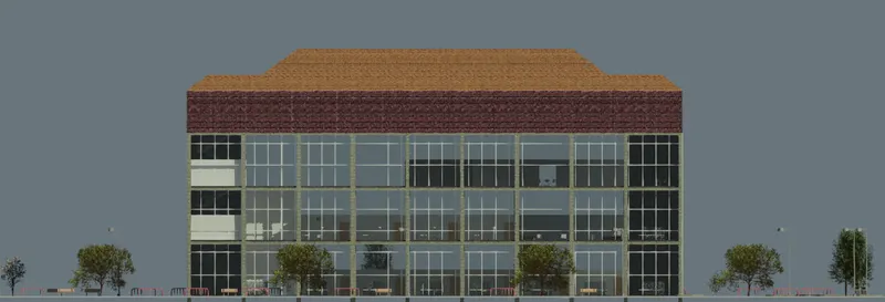
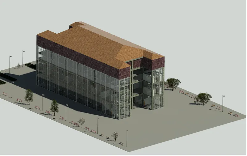
Results - Rendering views are created
1)
2) Rendering View of Interior rooms -
3) Rendering View showing topography features
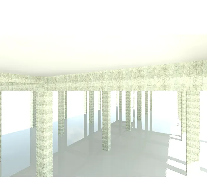
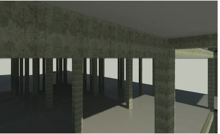
3) Rendering View of Structural Element
7. Aim - To Print the set of drawing sheets created and submit the drawings from the architecture and structure model.
Procedure -
Step 1
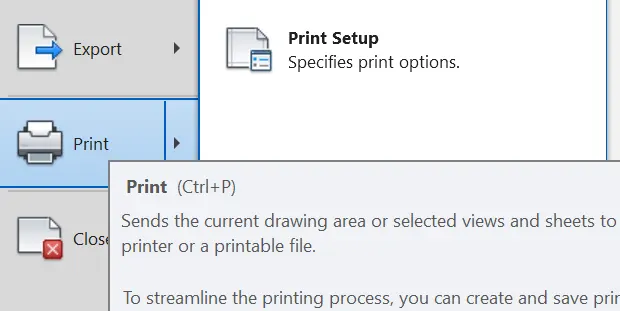
i) Click the views and open file menu and click the print.
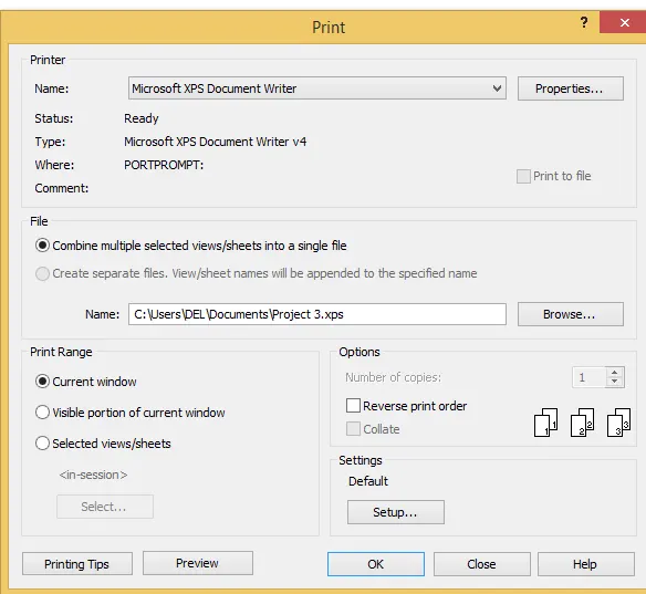
ii) Print dialog box will appear.
Step 2)
i) No we have to change the settings of sheets size ,texts styles page setup etc
 .
.
Step 3)
i) After Setting all the things then
ii) Click Ok.
Results - So we have crerated a set of drawing ( Architectural and Structural ) and we have taken the print also.
1) Elevation View Sheet
2) Floor Plan Sheet -