Creating Kitchen layout, Hatching of Architectural elements and sectional view of an Industrial Building in AutoCad
Creating Kitchen layout, Hatching of Architectural elements and sectional view of an Industrial Building in AutoCad
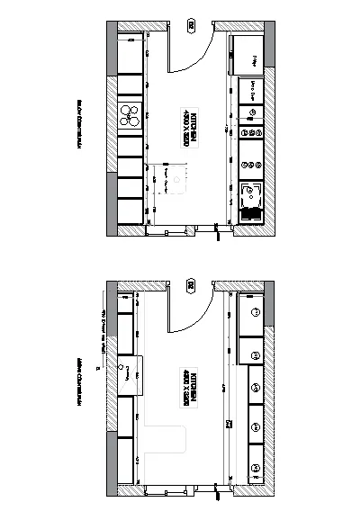
1} AIM : Create the layouts of the Kitchen and provide hatches pattern as shown. Also, use blocks wherever required. Provide appropriate dimensions in the plan. Assume the size of doors, appliances and others as per the standards.
Introduction: we draw kitchen layout using Autocad by using commands Draw and Modify commands like LINE, CIRCLE, OFFSET, ARRAY, DIMENSIONS, TEXT, COPY, ARRY, LAYER & RECTANGLE command and hatch command.
#Procedure:
step1)
Make a outer boundry or external walls
choose line command
or choose a rectangle and from toolbar
draw a rectangle of size 4300,3200mm
take offset from OFFSET command
and give outer side offset of 300mm both sides as a wall thickness
draw a blocks betwwn walls
and take masonary hatch from HATCH command
with proper size
and also take solid hatch for concrete work and gives layer
and draw door using circle of opening 900mm
from circle command and line command
and also draw other side door op 800mm opening size with 200mm width
and draw door with hingeds showing and draw 1 horizontal line at diffrent elevation at door
and draw random lines for making lock
showing bottom of that door in wall as opening mechanism of door with the help of rectangle and line command
step2)
internal partition
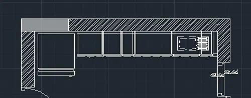
for top p[artition
take offset with horizonatal axis from top horizontal line as 35mm
by using OFFSET command
then take other offset on 490mm and then other at 20mm as partition
then draw at 600mm from top horizontral line as section line
then take offset for fridge 800mm from top
then for bottom stand take 200m depth rectangle and draw stand with 1 support leg
now go for verticle axis and take offset from verticle line at 35mm trhen 965mm for fridge
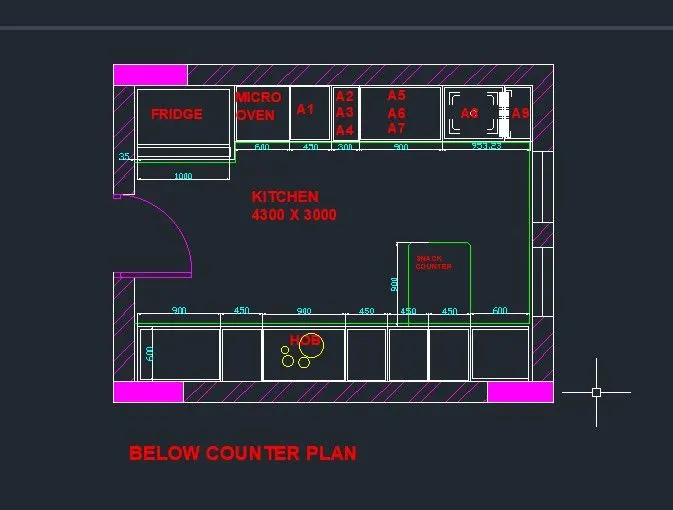
then again 20mm then 600 for micro oven then again offset of 450mm as A1
then take offset of 300mm for A2, A3, A4
again offset of a distance 900mm as A5, A6, A7
and now take offset of 300 and 945 mm as A9, and a10 respectively
in all between give 20, 20 mm bracket as partition
and draw design on A9 and A10 by using line,circle and fillet
step 3)
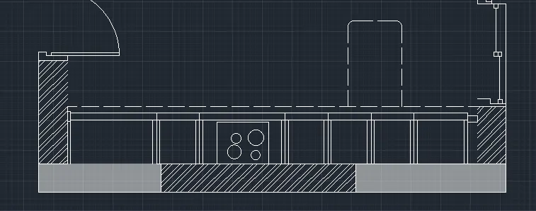
bottom partition
go for horizontal lines (axis) and take OFFSET command
offset from bottom hoeizontal inner line to uipward at a distance of 20mm
then another offset of 490mm and other offset of last line as 20mm
and take offset of first horizontal line at 600mm as section line
then go for vertical line [left side]
take first offset of 35mm then take offset of 900mm
now take offset of 450mm and another offset of 900mm from last line
then again 450mm offset for 3 times
then last offset of 560mm and 35 mm at end
in all between give 20, 20 mm bracket as partition
then draw horizontal section line at 600mm from selecting section line from line layer
then draw snackes counter of 600mm X 900mm with section line from 700mm from right side
then draw circle on hob by using circle command draw circle of diffrent diameters
step4)
dimensions and text
give dimension and text to architectural plan
text
by using DTEXT command or from annotation bar
edit the text by edittext and go for modify option
take scale as 300mm for text height and standard fond
after modifying setting give all required text by using single and multi text
now dimension
go for dimension command typing DIM
or from annotation bar
modify setting as D enter and set fit
and overall height as 250mm and primery unit as decimal
and set proper precious
and showing all linear dimension using continue dimension command
#Procedure: for second kitchen
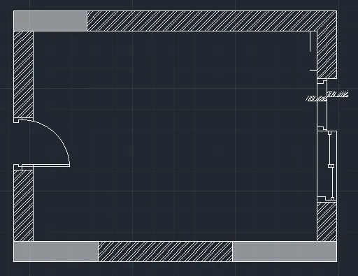
step1) make a outer boundry or external walls
choose line command
or choose a rectangle and from toolbar
draw a rectangle of size 4300,3200mm
take offset from OFFSET command
and give outer side offset of 300mm both sides as a wall thickness
draw a blocks betwwn walls
and take masonary hatch from HATCH command
with proper size
and also take solid hatch for concrete work and gives layer
and draw door using circle of opening 900mm
from circle command and line command
and also draw other side door op 800mm opening size with 200mm width
and draw door with hingeds showing and draw 1 horizontal line at diffrent elevation at door
and draw random lines for making lock
showing bottom of that door in wall as opening mechanism of door with the help of rectangle and line command
step2) internal partition
for top p[artition
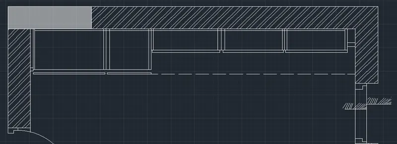
take offset with horizonatal axis from top horizontal line as 35mm
by using OFFSET command
then take other offset on 490mm and then other at 20mm as partition
then draw at 600mm from top horizontral line as section line
then take offset for A13,A14 and A15 350mm from top
now go for verticle axis and take offset from verticle line at 35mm trhen 965mm for A11
then again 20mm then 600 for A12 then
then take offset of 834mm for A13, A15, A15
in all between give 20, 20 mm bracket as partition
step 3)
bottom partition
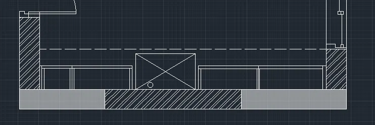
go for horizontal lines (axis) and take OFFSET command
offset from bottom hoeizontal inner line to uipward at a distance of 20mm
then another offset of 350mm and other offset of last line as 20mm
then go for vertical line [left side]
take first offset of 35mm then take offset of 450mm
now take offset of 900mm and another offset of 900mm from last line as chimney with 600mm height
then again 900mm offset for
then last offset of 1010mm and 35 mm at end
in all between give 20, 20 mm bracket as partition
then draw chimney of 900mm X 600mm with cross lines
then draw circle on botoom side 1650 from first left vertical line as exhaust pipe offset
step4)
dimensions and text
give dimension and text to architectural plan
text
by using DTEXT command or from annotation bar
edit the text by edittext and go for modify option
take scale as 300mm for text height and standard fond
after modifying setting give all required text by using single and multi text
now dimension
go for dimension command typing DIM
or from annotation bar
modify setting as D enter and set fit
and overall height as 250mm and primery unit as decimal
and set proper precious
and showing all linear dimension using continue dimension command
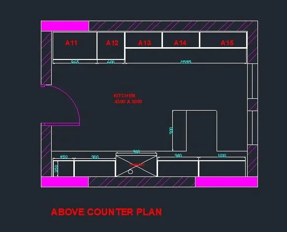
#Result: we create a kitchen layout various commands like line, layer, circle arc, dimensions, fillet and trim, text and hatches
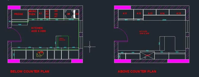
note: above kitchen layout pdf file attach to challenge for refrence as kitchen layout
2} AIM: Create the elevation of the plan created in the Challenges 7 and apply proper hatch in the walls, doors, windows, and other architectural elements. Refer to the dimensions in Plans and sections in Challenges 7.
Introduction: we draw elevation of challenge no 7 plan by using hatch command and various drawing and modify commands all dimension taken as per challenge no 7
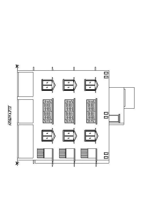
Procedure:
step1) draw outer border/ boundry of plan
draw outer border of plan by using line command
set unit as decimal (meter and MM)
XLINE or rectangle command
and draw rectangle of @11250mm X 12000MM
in witch height is 2450 for ground floor and 2850 each for 1st,2nd and 3rd floor
after that 1000mm parapet wall height
with 300mm projection column from first floor
step2)
draw window with chajja and balcony, ground floor shutter
by using line command draw ground floore shutters projections
at a size of 1500mm, 1500mm and 2500mm respectively
with 50mm gap distance or offset at every space
then balcony at every floor with 1200mm X 2100 mm
and window of size 1000X1200mm with upper design as shown in fig, window is sliding with double slide
then draw bigger opening in between two windows as 2000X1200mm
and by offseting that rectangle with 35mm and give hatch in middle rectangle by using HATCH command
and draw chajja of 400mm projection as per challeng 7 draw slope chajja of 1:75 slope
and draw balcony design using line command
step3)
draw head room and water tank
choose line command from ribbon or XLINE command
and draw head room with 2100mm height and 4000mm width at distance of 2300mm from left side
and draw head room door of 1000mm X 2100mm with lintel projection as per shown in dwg
then water tank
of height 1200 mm from left corner of head room with 2000mm width
step4)
dimensions and text
give dimension and text to architectural plan
text
by using DTEXT command or from annotation bar
edit the text by edittext and go for modify option
take scale as 300mm for text height and standard fond
after modifying setting give all required text by using single and multi text
now dimension
go for dimension command typing DIM
or from annotation bar
modify setting as D enter and set fit
and overall height as 250mm and primery unit as decimal
and set proper precious
and showing all linear dimension using continue dimension command
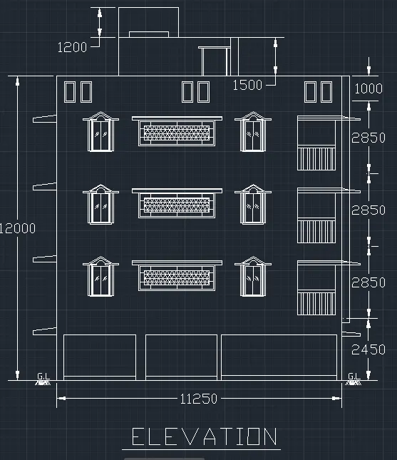
result: we draw elevation of challenge 7 plan by taking all plan dimension and proper required hatch bu using auto cad 2019, with text and dimension command and drafting commands, all dimensions are in mm
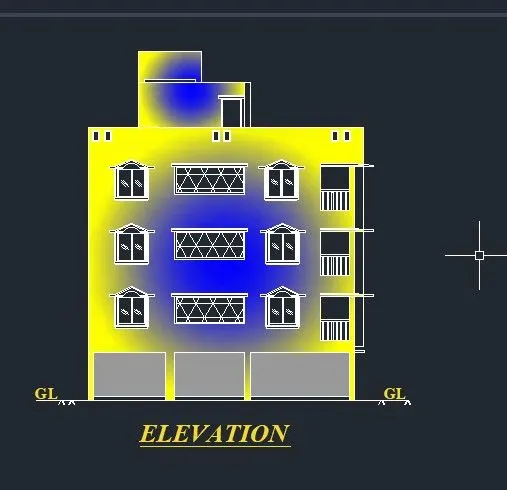
3} AIM: Create the section view of an industrial building as shown in Figure. Provide appropriate hatches and dimensions wherever required. Also, provide annotations to the drawing.
Introduction: create section for given dimension by using drafting and modify command on auto cad 2019 and give hatches for better understanding also use annotation for clear readable dwg
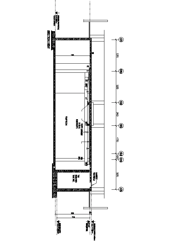
Procedure:
step1) make a wall layout and projections
set all dimension in mm (decimal unit)
choose line command from ribbon
draw horizontal line of sixe 5315,5320,3900,4720,1020,5025mm external to external
then offset upward at a distance of 300 mm as wall thickness
then take offset by using OFFSET command 5850mm then again offset of 300mm at last wall thickness
then go for vertical left side 300mm wall thickness same from opposite side 300mm wall thickness
then from right take 2500mm man hole with 300mm width
and draw all projection as shown in fig with proper dimension and distance
by using line, rectangle and offset command
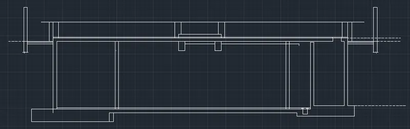
step2) duct, hatch and foundation
draw duct of 350 size with bent 200mm at left corner
with 300 mm wall at both end of duct
then hatch by using HATCH command
take concrete hatch from hatch option with 50scale
and draw foundation 400 mm deep with 1500mm width
also draw duct holder by using rectangle command
and hatch on foundation also
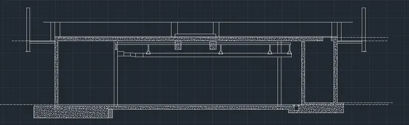
step3)
dimensions and text
give dimension and text to architectural plan
text
by using DTEXT command or from annotation bar
edit the text by edittext and go for modify option
take scale as 300mm for text height and standard fond
after modifying setting give all required text by using single and multi text
now dimension
go for dimension command typing DIM
or from annotation bar
modify setting as D enter and set fit
and overall height as 250mm and primery unit as decimal
and set proper precious
and showing all linear dimension using continue dimension command
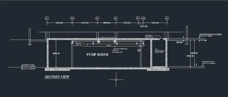
result: we draw section plan as per given dimension by using auto cad 2019 with various drafting and modifying commands with hatch and circle, we got redable section drawing
note: above section plan pdf file is uploaded to chalenge for refrence with section.pdf file