Creating Architectural and Structural model with 3D rendering using REVIT
1) Select the type of structure you want to build from one of the three below:
a. Multi-Unit Residential Apartment
b. Office Buildings
c. School
Aim : To select a type of structure from
a. Multi-Unit Residential Apartment
b. Office Buildings
c. School
Result : Selected Multi-unit residential apartment
2) Assume reasonable assumptions for geographic and location details for your project modeling. Based on assumptions and type of structure selected identify the modeling requirements from NBC
Aim : To assume reasonable assumptions for geographic and location details for Multi unit residential apartment.
To identify the modelling requirements for multi unit residential building from NBC.
- As mentioned above, the building comes under residential type and cabn be situated in any part of the city.
- The road width of the project is 60 feet.
- The height, area limits and safety measures are followed as per NBC.
- The height of project is 40 feet.
- The height of building should not exceed 1.5 times the width of the road, in this case the height didnot exceed 1.5 times the width of the road.
Result :
Reasonable assumptions are made for geographic and location details for Multi unit residential apartment.
Modelling requirements for multi unit residential building are obtained from NBC.
3) Using the structural model, include the following components based on the type of structure selected
a. Foundation – Isolated / Wall/Matt Foundation
b. Columns
c. Beams Connected to Columns
d. Roof Framing/ Truss
e. Floor / Decks
f. Floor Openings for Elevators and Stairs
Aim : To include the following components in a structural model of multi unit residential building.
Procedure :
- Two separate templates, namely architectutal and structural have been already created and collaborated into a single template which is constructional.
- A new architectural template is opened and named appropriately
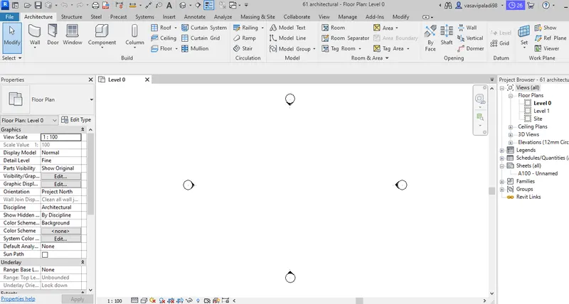
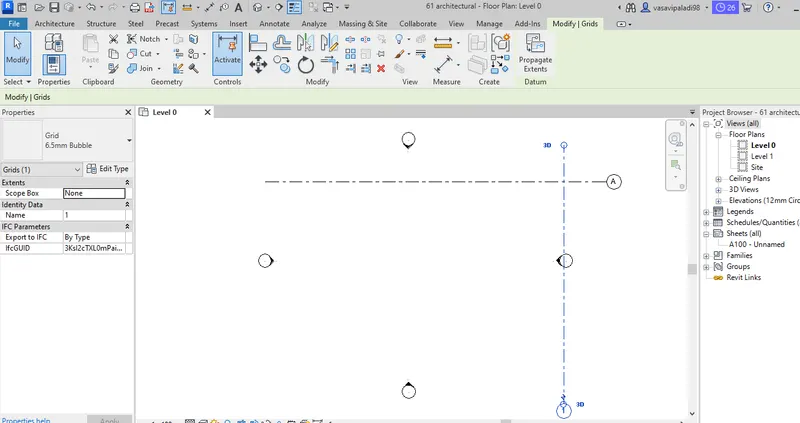
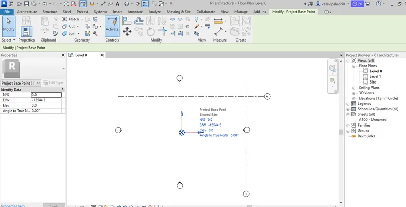
- Grids are made and project coordinates are specified using coordinates option in manage tab
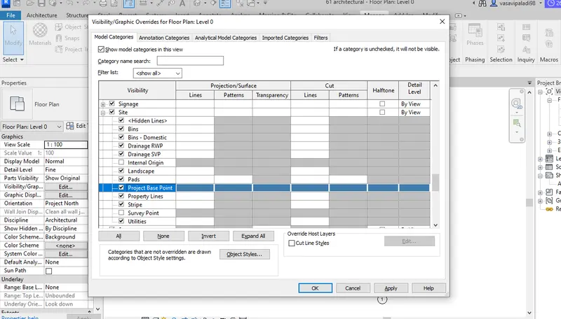
- project base point is defined using visisbility graphics (VG)
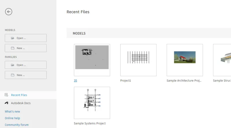
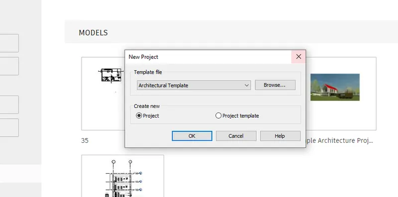
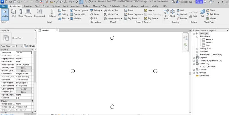
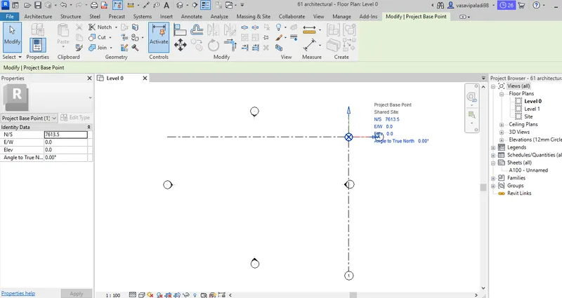
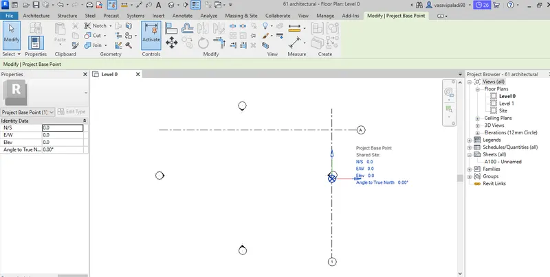
- A new structural template is opened and named appropriately
- Grids are made and project coordinates are specified using coordinates option in manage tab
- project base point is defined using visisbility graphics (VG)
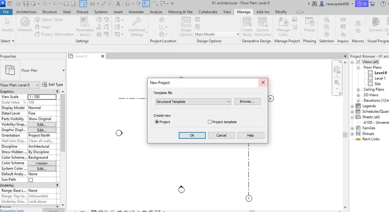
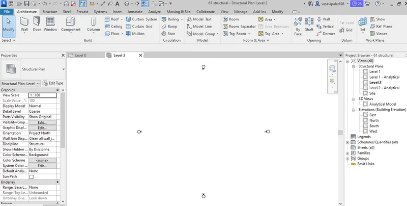
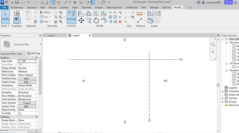
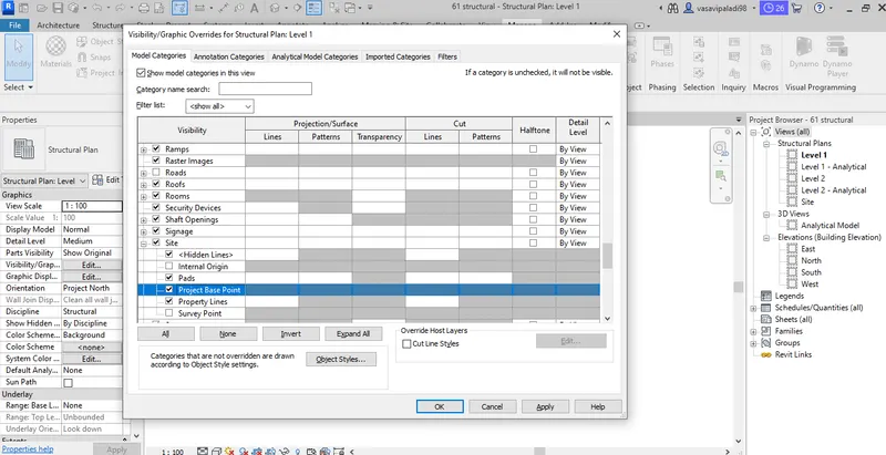
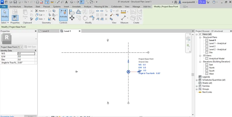
- Architectural model which was created previously is opened
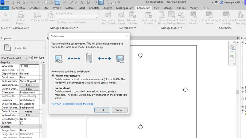
- Made as central model using collaborate option from collaborate tab
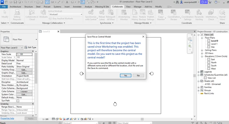
- Finally saved the project to save the present project to central model
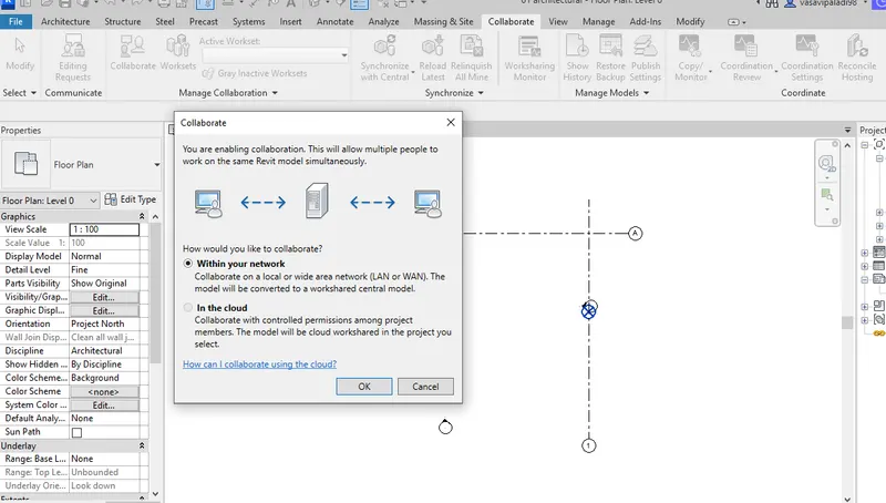
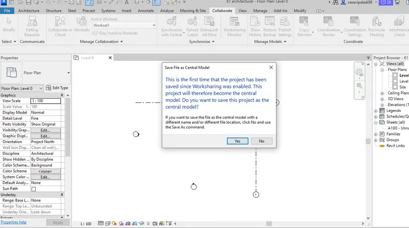
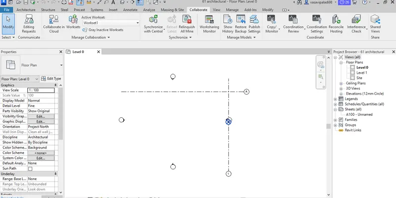
Grids are created using grids option from architectural tab
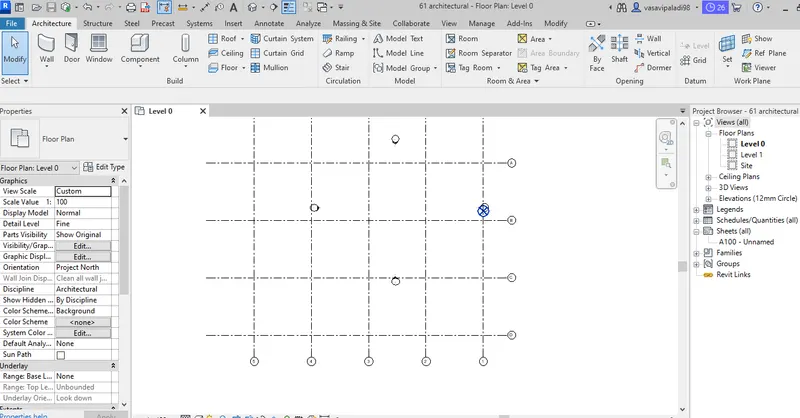
There are two ways to synchronise a project
- Using the direct synchronise icon on to top left

2.Using the same synchronise option from collaborate tab
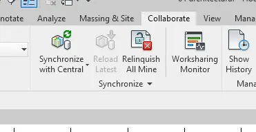
In th synchrose dropdown menu there are two option, when used "synchronise and modify setting", the tab below pops up when clicked ok the project will be synchronised
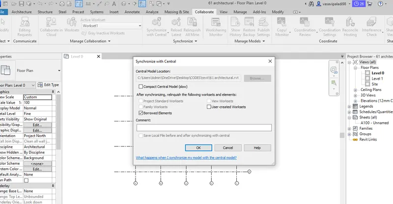
Note :
one more option with synchronise collaborate tab is "synchronise now" which can also be used directly to synchronise the changes made to the central model
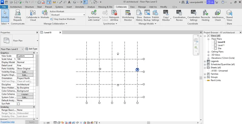
- Structural model which was created previously is opened
- Made as central model using collaborate option from collaborate tab
- Finally saved the project to save the present project to central model
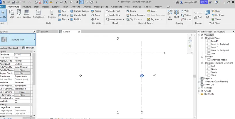
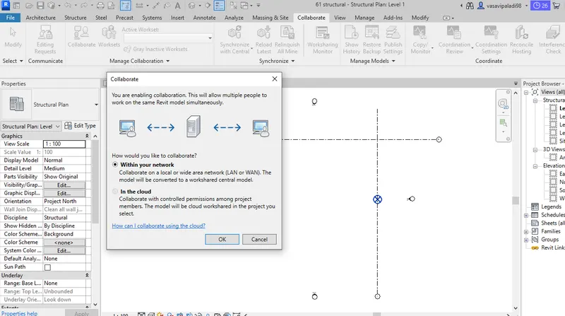
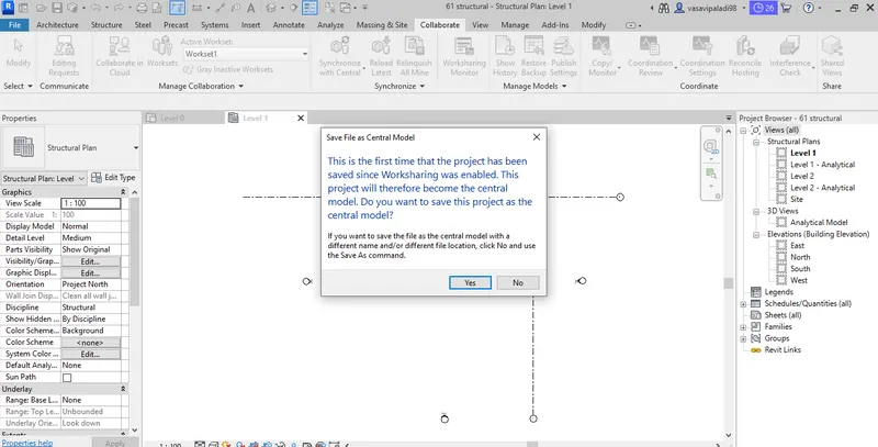
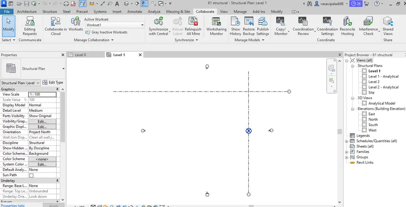
Structural template which was made as a central template previously is opened and architectural template is in serted into it using insert tab>Revit link and the inserted link is copied using the copy/monotor option in collaborate tab
Visual graphics (VG) is used to check if the architectural template is copied to the structural template, to insert a template into the other, the template to be inserted must be closed in revit
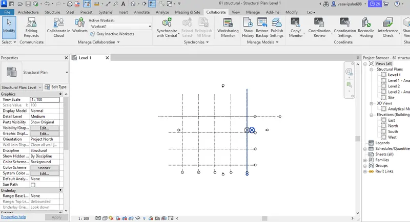
Collaborate tab is used to copy the grids and after copying the grids from architectutal template to the structural template, the coordinates of both the templates are merged into the same point (which is possible because the origins are assumed as such to achieve this) ie, the copy procedure happend from origin (of architectural template) to origin(of structural template)
- A Structural model is created and named
- Made as central model using collaborate option from collaborate tab
- Finally saved the project to save the present project to central model
- Previously created structural and architectural file is added using manage links option
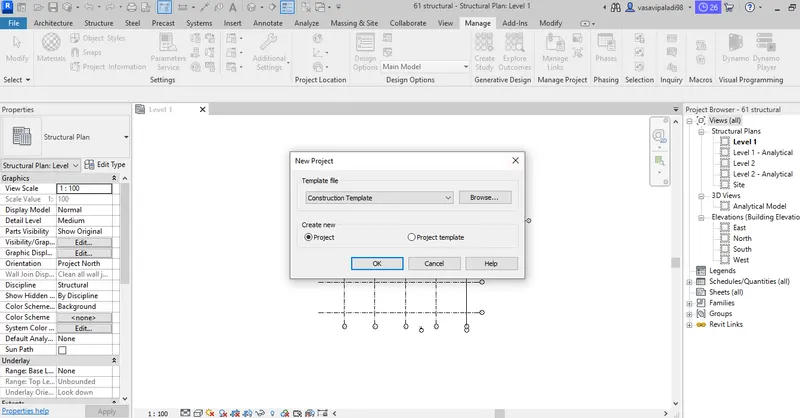
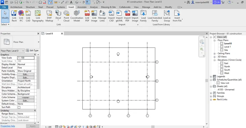
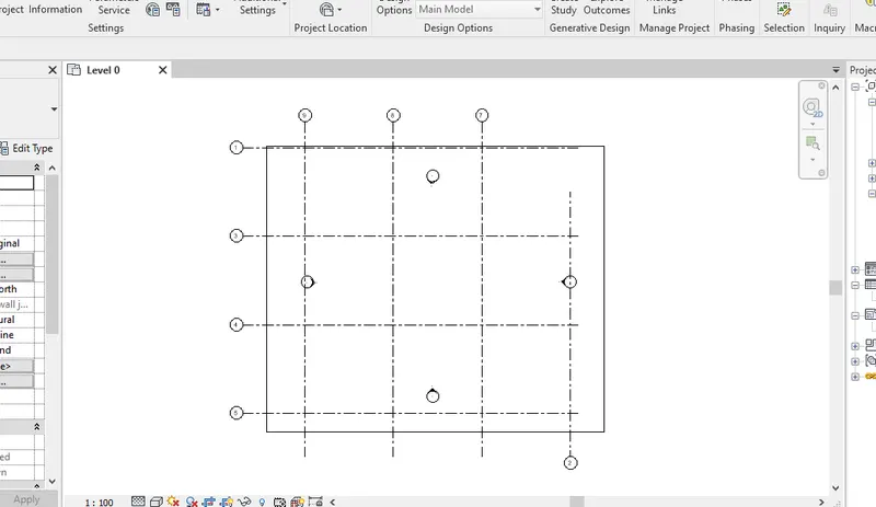
The grids from structural and architectural model matching in the construction template created
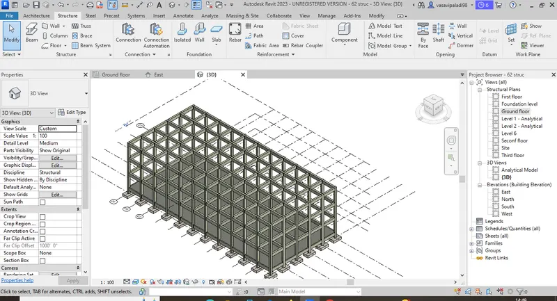
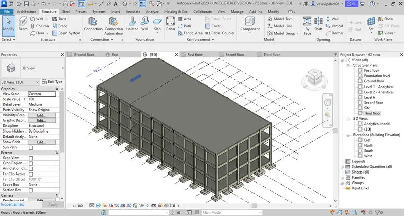
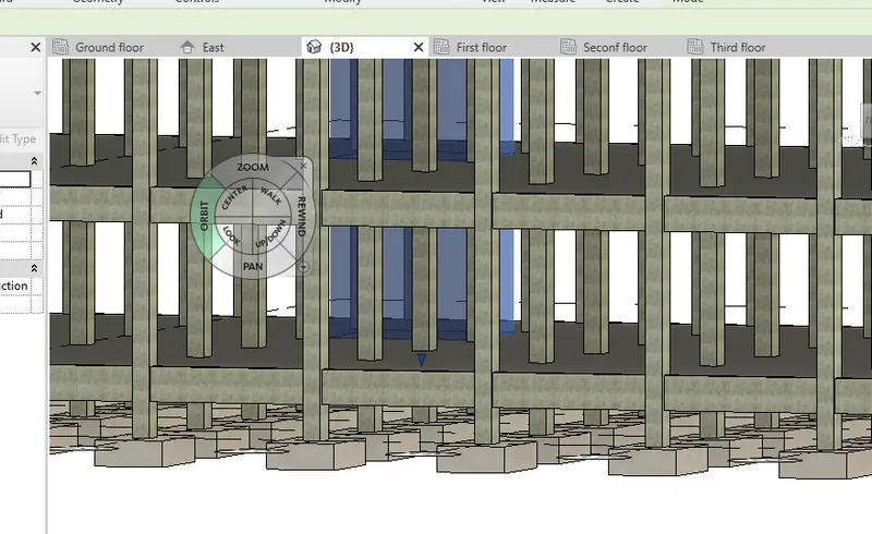
- Different commands such as template, structural template, Grids, columns, beams, foundations, stairs, shafts, floors Etc are used to create the required structural model with the elements such as foundation, columns, beams, roofs etc.
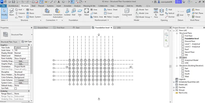
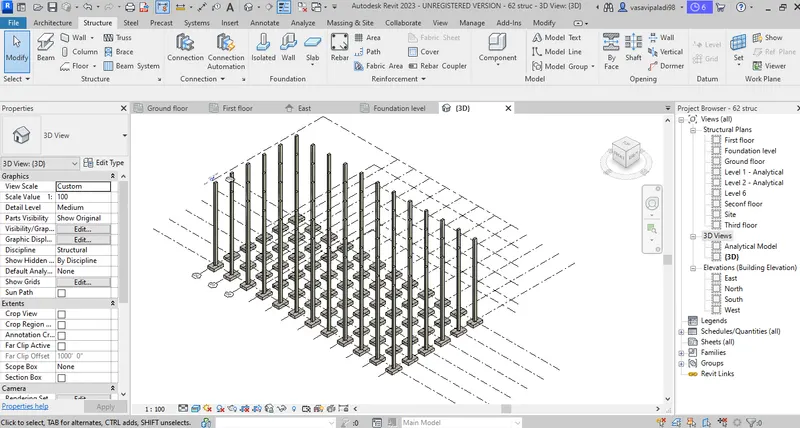
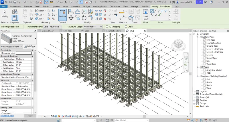
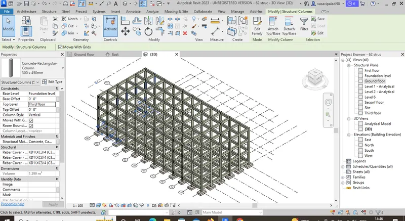
Result :
In this project structural model is used and later collaborated and made as a central model after adding all the elements.
4) Using the architectural model, include the following components based on the type of structure selected
a. Wall Layout with appropriate material and finishing
b. Exterior façade with fancy finish
c. Interior partition walls to size rooms
d. Components to add details to a room ( Desk, Chair, Lighting, Plumbing fixtures)
e. Add components such as stairs Elevators
f. Have at-least one side of the building with curtain walls and glass panels
g. Include interior and exterior lighting fixtures
h. Place proper topographic components from outside ( Trees, Parking, Plants) to add details to the model
Aim : To use the architectural model and to include the following components
a. Wall Layout with appropriate material and finishing
b. Exterior façade with fancy finish
c. Interior partition walls to size rooms
d. Components to add details to a room ( Desk, Chair, Lighting, Plumbing fixtures)
e. Add components such as stairs Elevators
f. Have at-least one side of the building with curtain walls and glass panels
g. Include interior and exterior lighting fixtures
Commands used :
- Arcitectural
- Walls
- Components
- Load family
- Floors
- Doors
- Windows
Procedure :
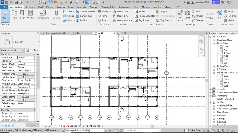
Now, go to the architectural template and by using add link optioon the structural template is linked to the architectural template and elements such as exterior wall, doors and other componenets are added using the architectural tab.
Later, the camera is set to render the finished model and sections are created using section option in view tab.
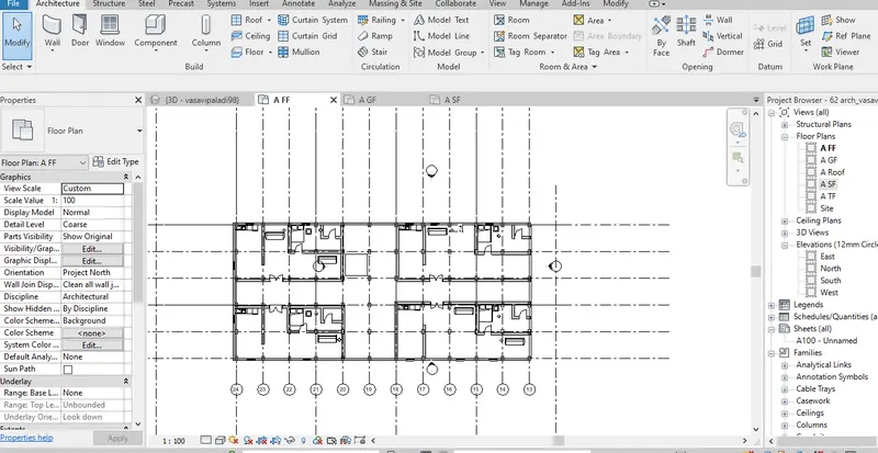

Result :
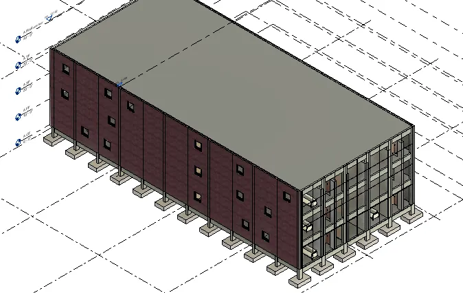
5) Provide a set of drawings in an architectural and structural model to list the following details with categories and appropriate sheet templates included
a. Floor Plans with Annotations
b. Elevations
c. Sections
Aim :
To provide a set of drawings in an architectural and structural model to list the following details with categories and appropriate sheet templates included
a. Floor Plans with Annotations
b. Elevations
c. Sections
Commands used :
- Insert
- Sheets
- Load families
- Edit sheets
- Load images
- View
Procedure :
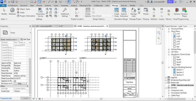
Sheets from the existing families can be sleceted or new sheets can be loaded from load families option in view tab. Required views can be pasted and the sheets can be frenamed. These sheets contain sections, elevations, plans etc.
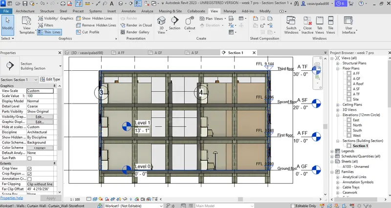
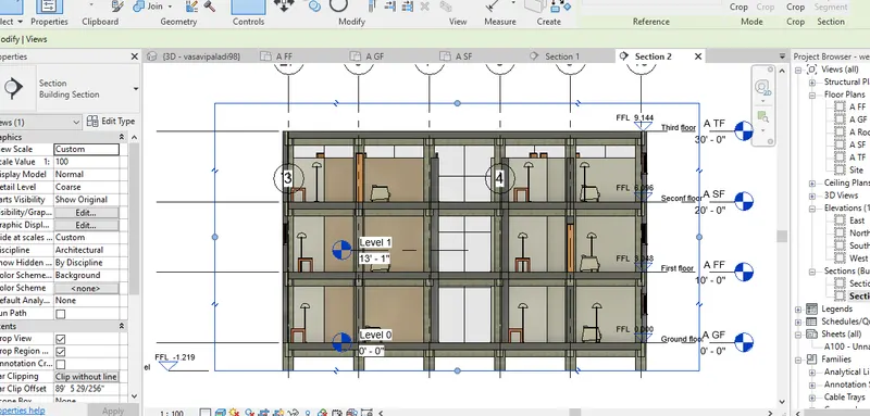
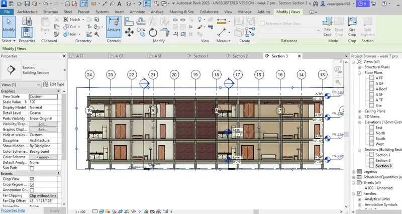
Result :
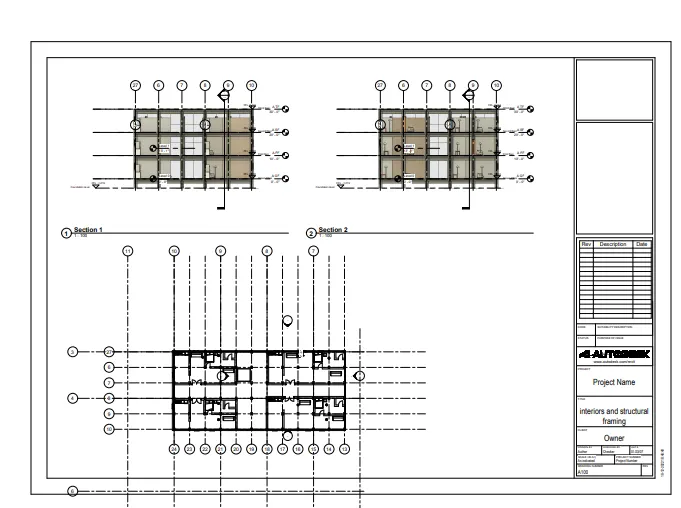
All the views created above are used to create sheets as shown below.
6) Using the Rendering settings, Render images of the 3D model produced and include the rendered images to the drawing sheets
a. Rendering from interior rooms
b. Rendering from out showing topographic features
c. Rendering through structural framing
Aim:
To craete the render images of the 3D model produced and include the rendered images to the drawing sheets
a. Rendering from interior rooms
b. Rendering from out showing topographic features
c. Rendering through structural framing
Commands used :
- Render
- Region
- Style
- Scheme
- Sheet
Procedure :
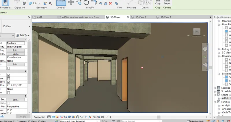
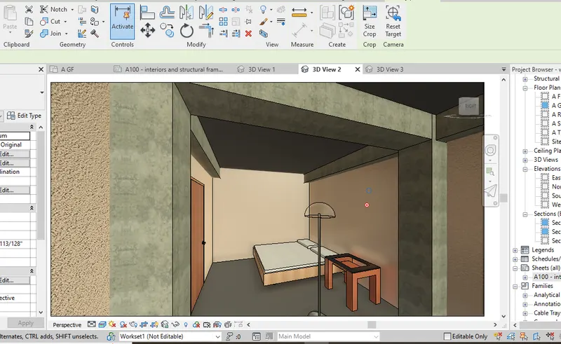
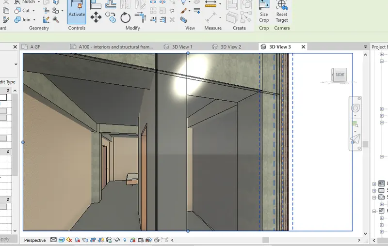
Camera option in the 3D view is used to create different render images as shown below.
These images can be cropped and expanded as per gthe requirement
Relistic render images can be created by changing visisbility settings to realistic
Result :
7) Print the set of drawing sheets created and submit the drawings from the architecture and structure model
Aim : To print the set of drawing sheets created and submit the drawings from the architecture and structure model
Commands used :
- File
- Setup page
- Select the plotter
Procedure :
Go to file menu and click on print , a print dailouge box as shown below appears
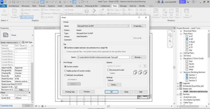
Select all the required options to print the sheets and click on print
A pdf is automatically created before the sheet gets printed
Result :