Project 1 _Creating an Architectural plan for the provided plot size and develop relevant basic structural drawings
AIM
To draw reisdential bulding of plot 60'x20' facing east with Architectural Drawing (Floor Plan, Elevations, and Sections) Structural Drawing (Column, Bean, Footing Plan).
INTRODUCTION:
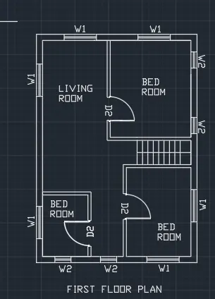
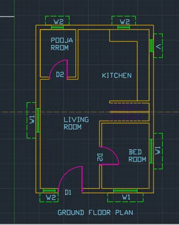
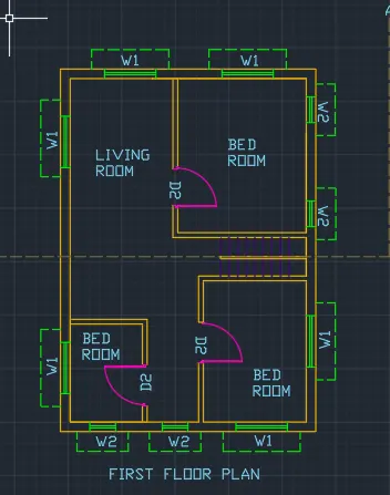
A G+1 residential building plan is made using autocad with dimensions as mentioned below
- External walls of thickness 9"
- Internal walls of thickness 4.5"
- Doors of D1 of dimension 4'x4'6" and D2 of dimension 3'x4'6"
- Windows (W1) of dimension 4'x3' and W2 of dimensions 2'x3'
- ventilaror of dimension 2'x2'
- Stair case of tread 8" and riser 4.5" with 16 steps for each stair
- compound wall of thicness 9" and height of 6'
PROCEDURE
- Open auto cadd and set units as per requirements (feet and inches, engineering)
- Set limits of drafting area using "LIMITS" command
- Different commands such as
UNITS: To set the required units
DIMSTYLE: TO set the different propertied of dimensions like line type, spacing
LINE: To draw lines
REC: To draw rectangles/squares
CIRCLE: To draw circles with available parameters like radius
TRIM: To trim the excess lines/ parts of drafting
OFFSET: To create/copy an object with specified spacing
FILLET: To create curved/ sharp end corners
DIM: To edit or set dimensions
DTEXT/MTEXT: To create text of single line or multi lines
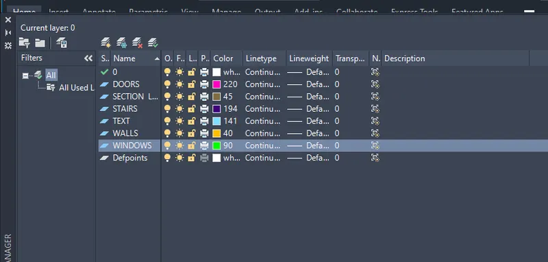
Other than these some other command such as layer properties, copy, move etc are also used for drafting the plans and sections given below
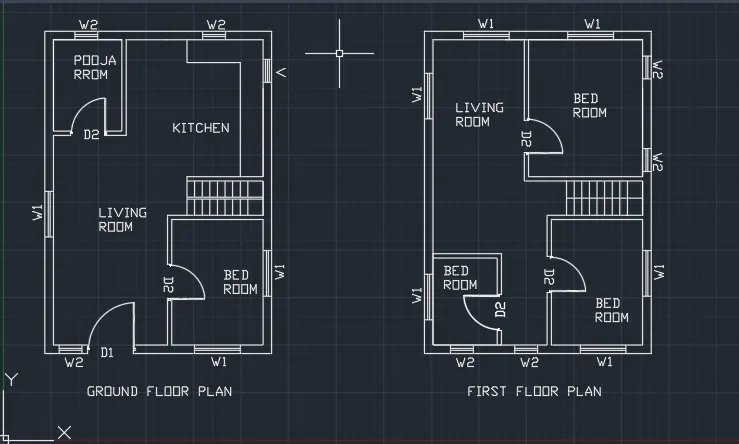
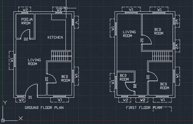
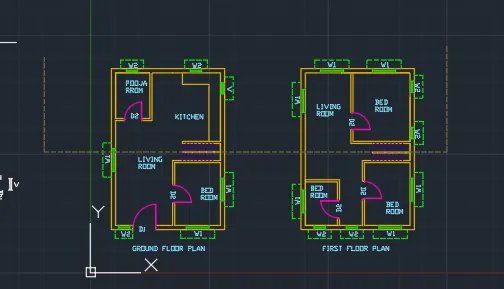
RESULT
All renderings have been done with the mentioned dimensions and the results are
Architectural drawings
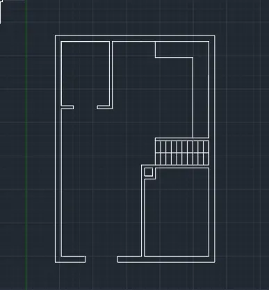
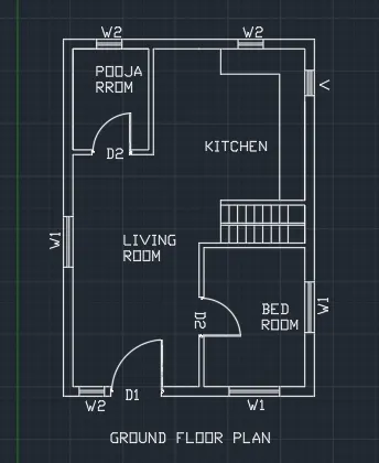
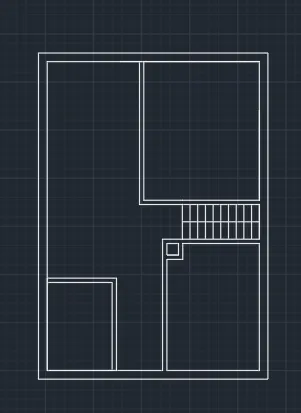
BOTH PLANS
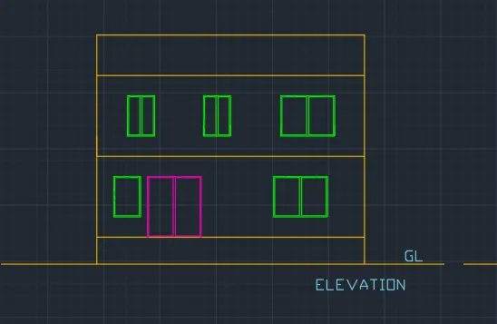
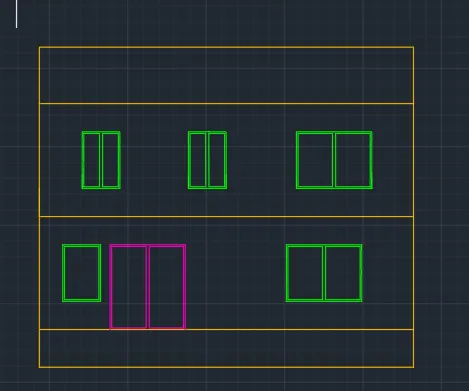
ELEVATION
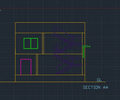
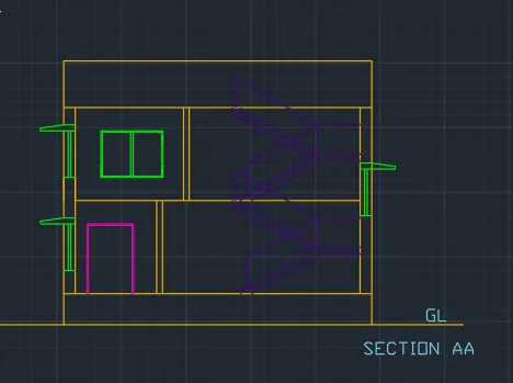
SECTION AA
STRUCTURAL DRAWINGS
PLINTH BEAM LAYOUT
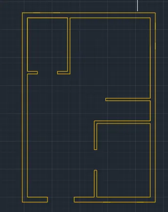
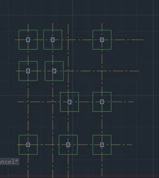
CENTRE LINE DRAWING AND COLUMN LAYOUT
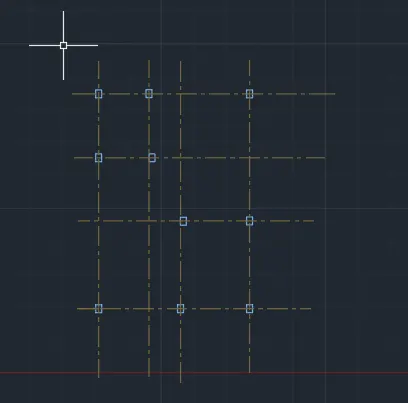
FOOTING LAYOUT