Creating Architectural and Structural model with 3D rendering using REVIT
1)
The type of structure that i want to build is SCHOOL BUILDING.
2)
- as per the guidelines of NBC the verandah for Educational Buildings such a schools, colleges, Research Institutions 2.0 m
- the maximum height of the school building is 18.30 m in chennai.
- in chennai the floors restricted for schools are G+2Floors
- Front Setback 6m.
- Side Setback 6m.
- Rear Setback 6m.
- the width of the road abutting is 40' (12.5m)
3)
AIM
To create the structural model, include the following components based on the type of structure selected
Foundation – Isolated / Wall/Matt Foundation
Columns
Beams Connected to Columns
Roof Framing/ Truss
Floor / Decks
Floor Openings for Elevators and Stairs
INTRODUCTION
The structural model is created using revit software.
PROCEDURE
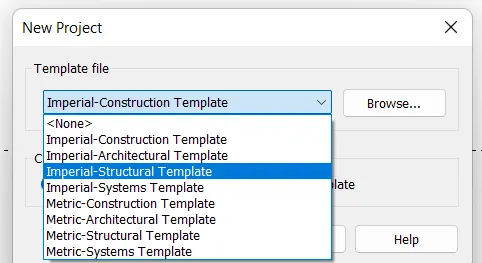
Open the structural template in the revit software.
create a new structural template.
select insert in the ribbon tab
slect the link revit in the toolbar.
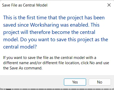
the file will be saved as a central model as shown in fig,
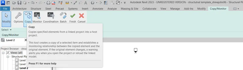
open the copy monitor tab in that select links. as shown below.

a tab appears on the riibon
slect the copy option and select the multiple and copy the total grids in the workplane
sucessfully the file have been linked with structural plan.
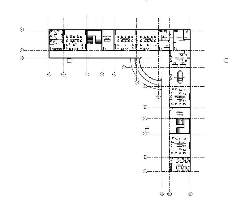
Type VG visibility graphics to visible the grids and plan in the revit link tab.
the foundation level in the ground level is created.
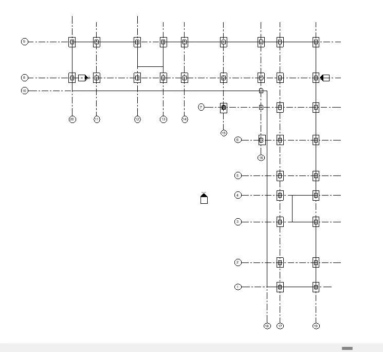
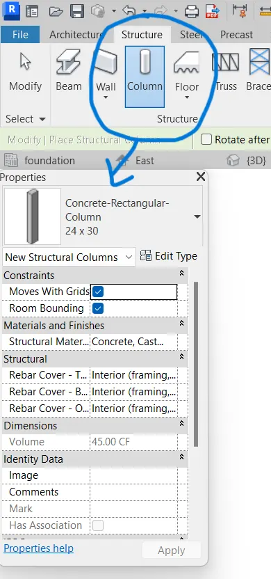
select the structural tab selct the column as shown in the fig.
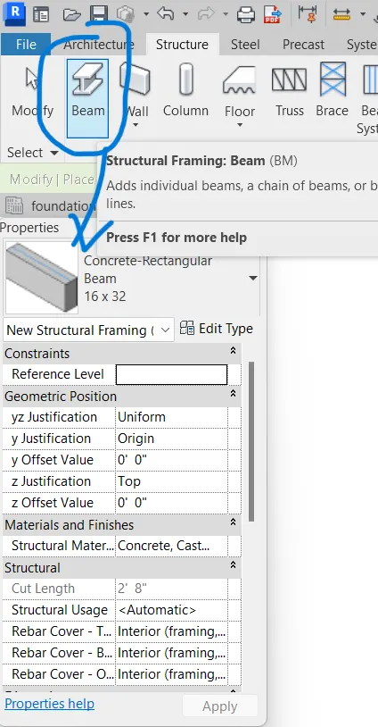
select the levels in the 2d view
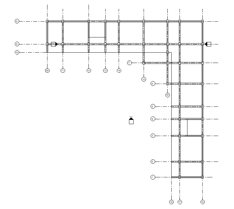
creating of column and beam in the first floor level.
3D view of column and beam to the top floor level is created.
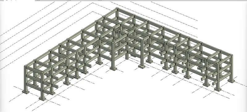
selecting of floor levels in the architectural or structural tab.
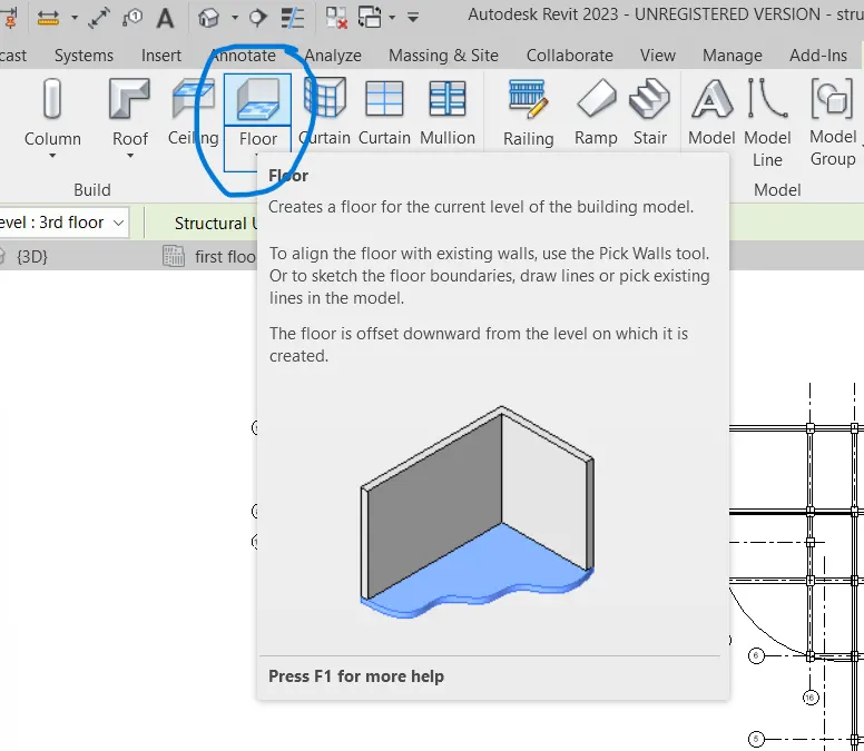
3D view of floors are created to the top level.
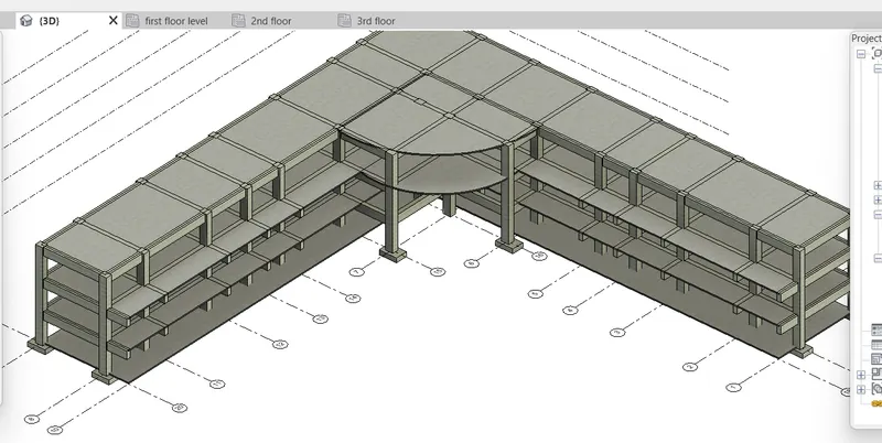
open architectural tab.
select the shaft tab in the right corner.
2D view of shaft created.
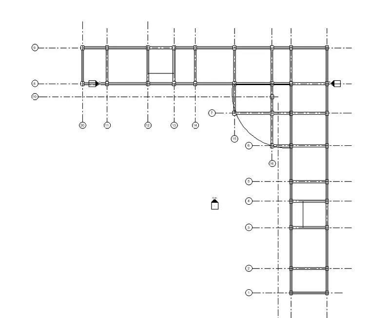
the shaft are created for opening of stairs.
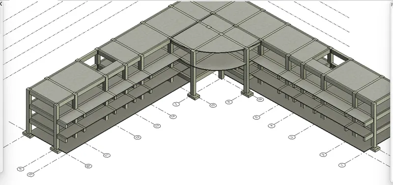
RESULT: The School building of structural elements is created using structural template is created and completed.
4)
AIM
T0 create the architectural model, include the following components based on the type of structure.
INTRODUCTION
the structure are created using revit software and the procedure are explained in detail.
PROCEDURE
Open the revit software
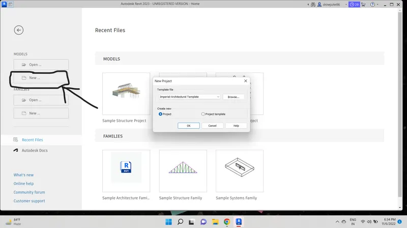
open select New.
select the architectural template
.
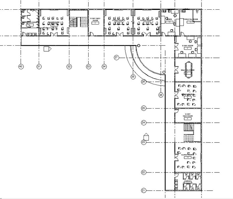
THE WALL ARE CREATED WITH APPROPRIATE FINISHING OF MATERIAL AS SHOWN BELOW
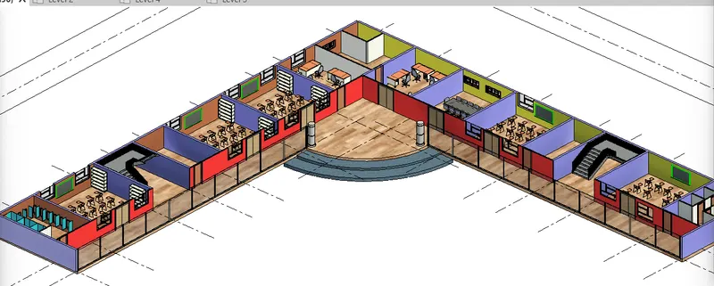
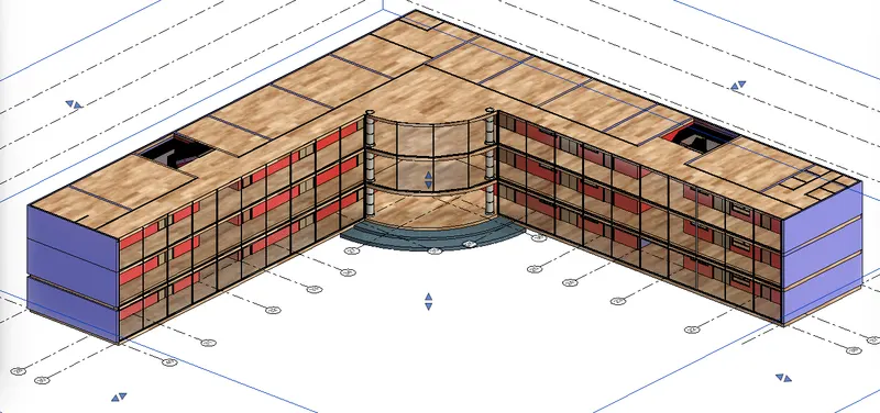
3D image of wall with finishing materials.
B) Exterior façade with fancy finish
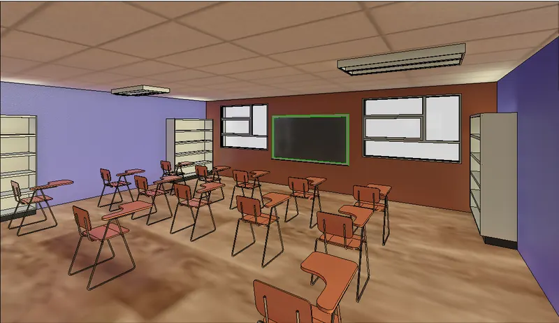
C)Interior partition walls to size rooms.
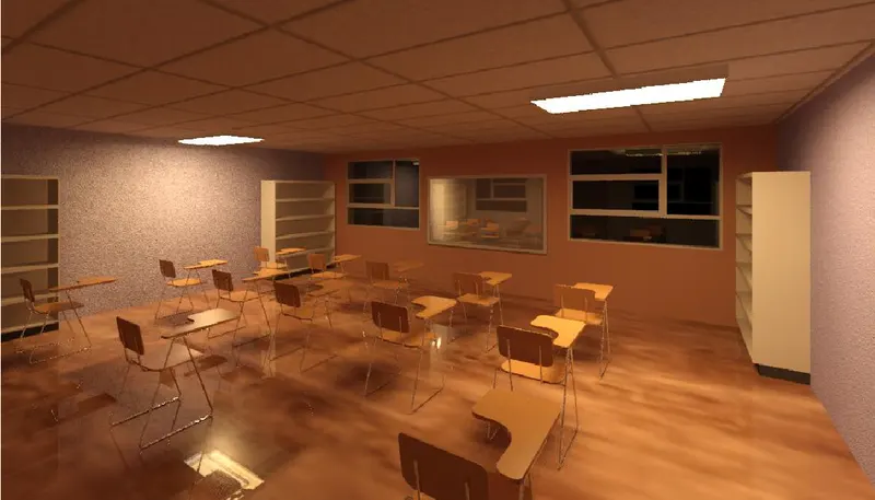
interior with lighting effect.
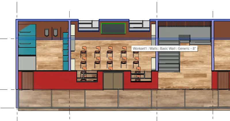
D)Components to add details to a room ( Desk, Chair, Lighting, Plumbing fixtures)
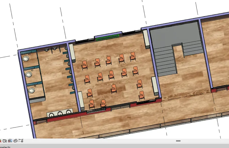
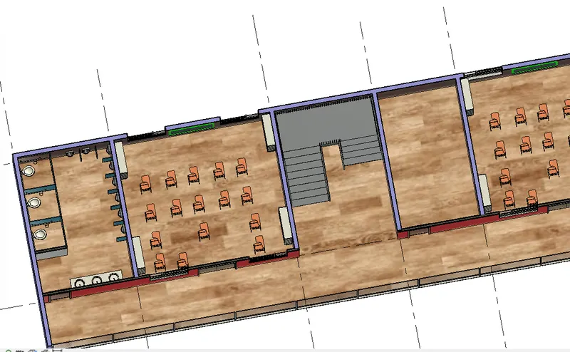
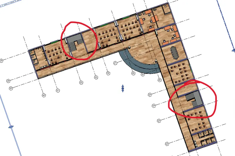
E)components such as stairs Elevators
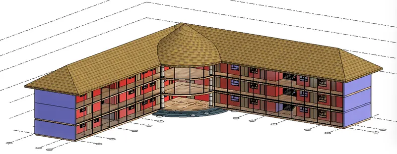
F)Have at-least one side of the building with curtain walls and glass panels
G)Include interior and exterior lighting fixtures
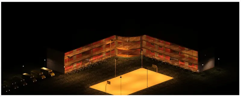
H ) Topographic components from outside ( Trees, Parking, Plants) to add details to the model
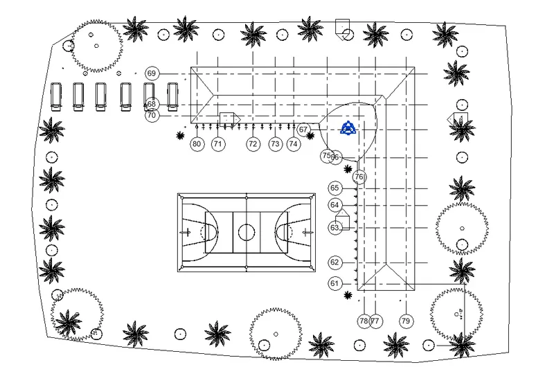
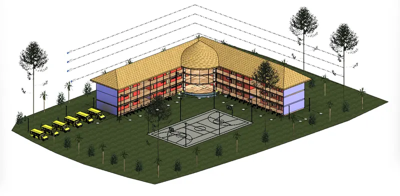
RESULT : the architectural model, include the following components is created an completed.
5)AIM
TO Provide a set of drawings in an architectural and structural model to list.
INTRODUCTION
the set of drawings are created in revit software.
PROCEDURE
Open the architectural tab.
select the view in the tool bar.
select the sheets in the toolbar.
A sheet will appear drag the view which ever is needed.
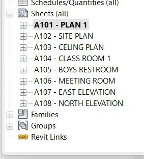
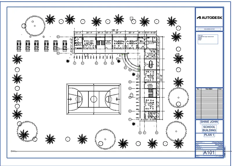
FLOOR PLAN LEVEL1
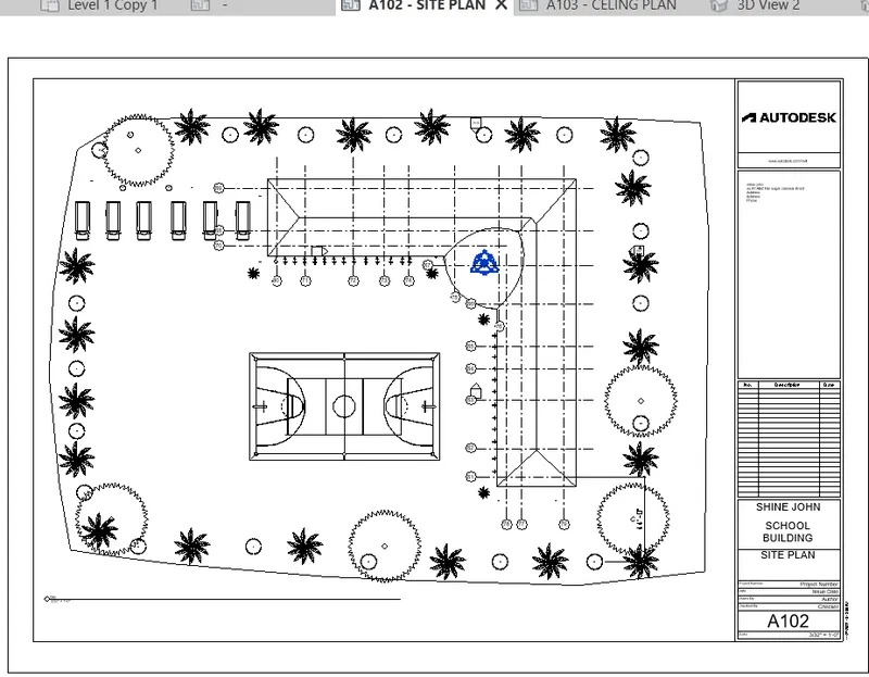
SITE PLAN
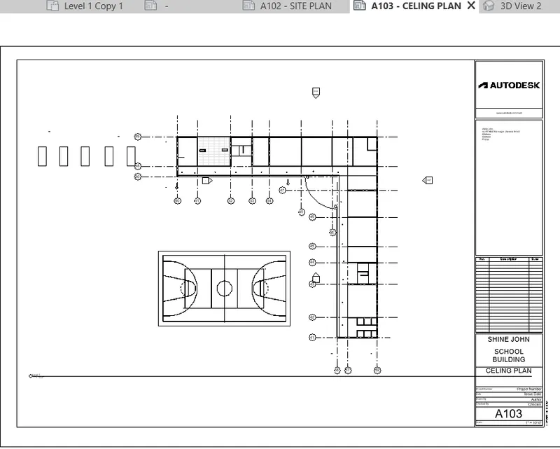
CEILING PLAN
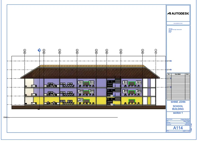
SECTION 1
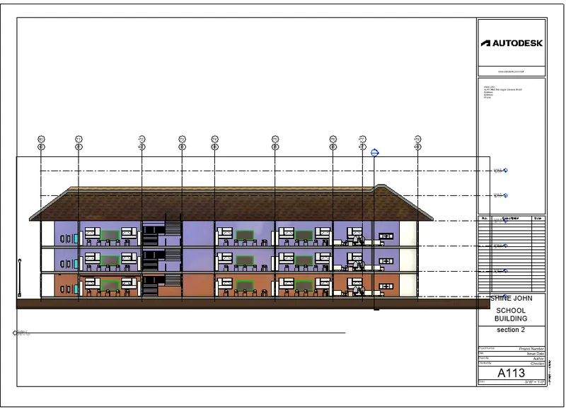
SECTION 2
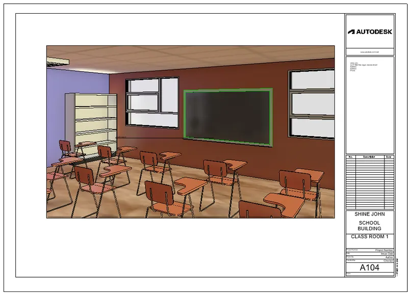
CLASS ROOM
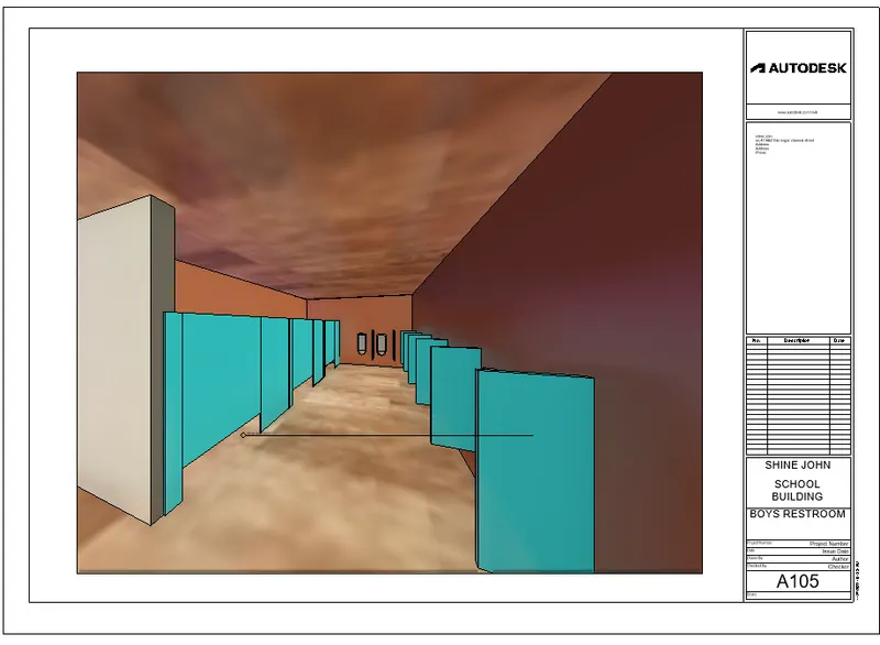
BOYS RESTROOM
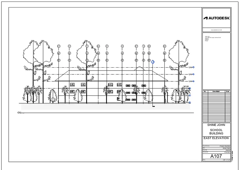
EAST ELEVATION
NORTH ELEVATION
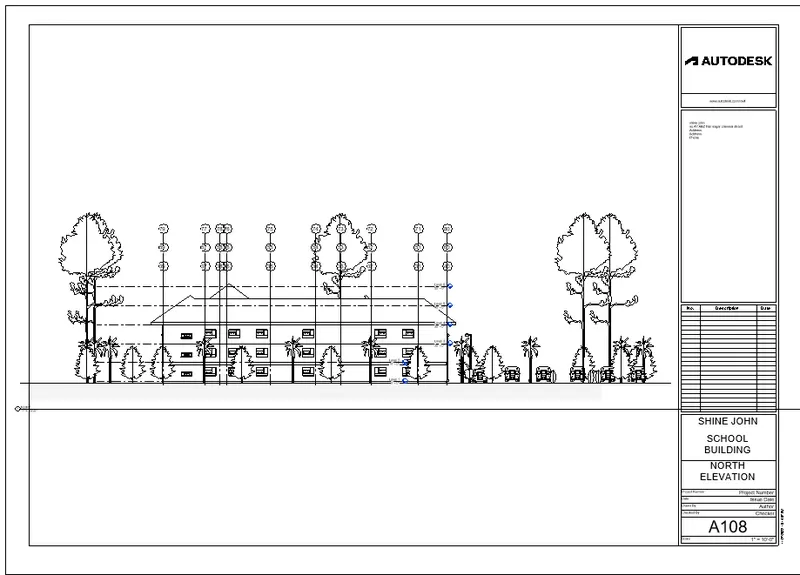
RESULT : The following set of drawings are attached to the sheet is completed.
6)
AIM
To create the Render images of the 3D model produced and include the rendered images to the drawing sheets.
INTRODUCTION
The following sheets are created using revit.
PROCEDURE
Open the architectural tab.
select the view in the tool bar.
select the sheets in the toolbar.
A sheet will appear drag the view which ever is needed.
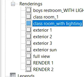
FRONT VIEW
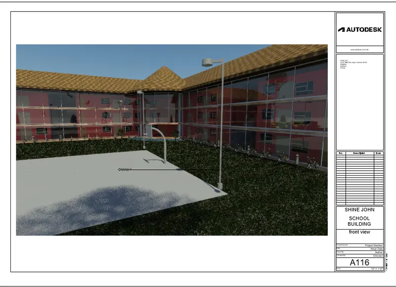
ENTRANCE LIGHTING
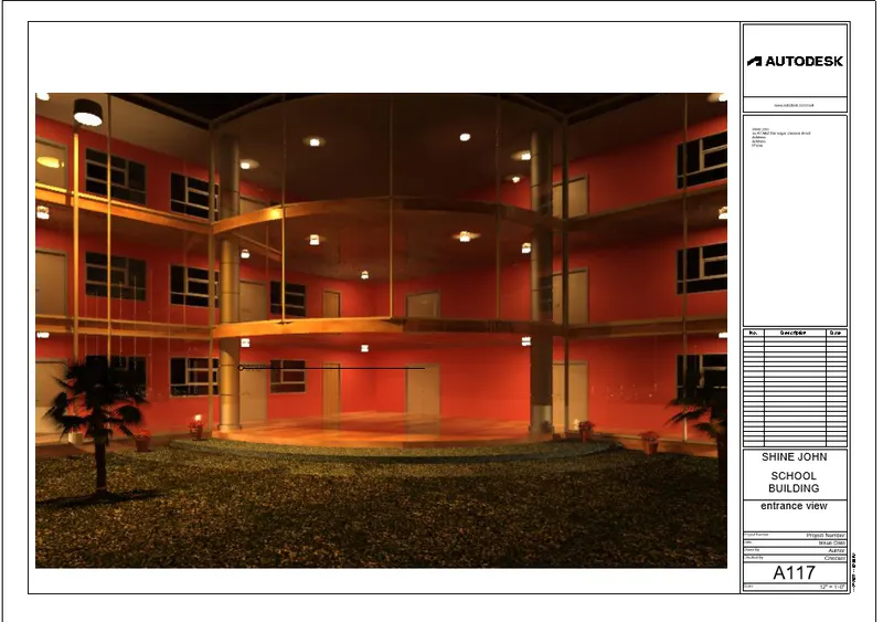
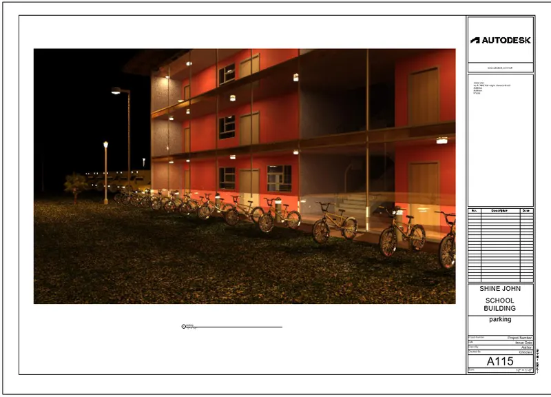
PARKING VIEW
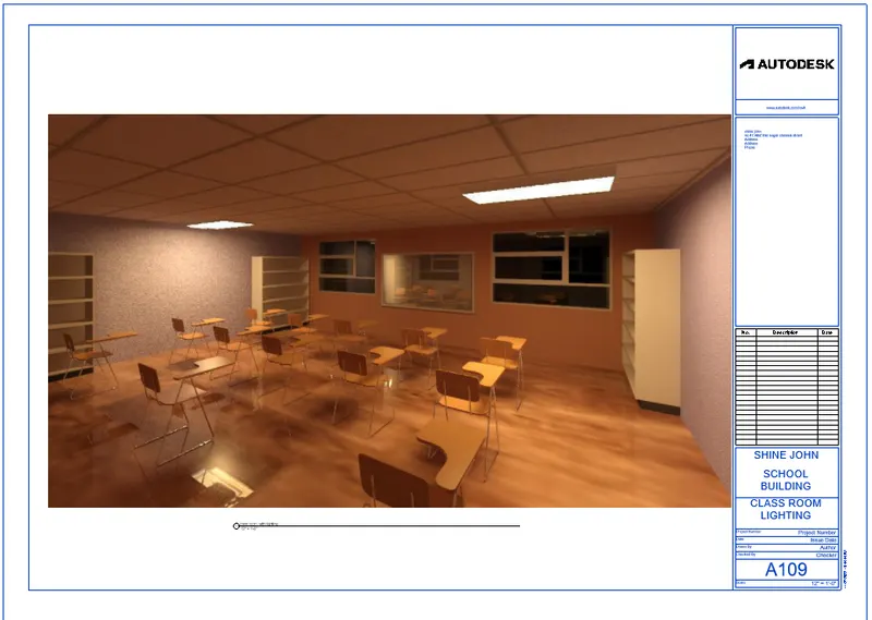
CLASS ROOM RENDERING
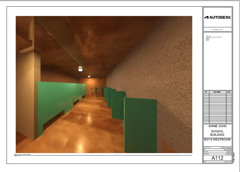
BOYS RESTROOM RENDERING
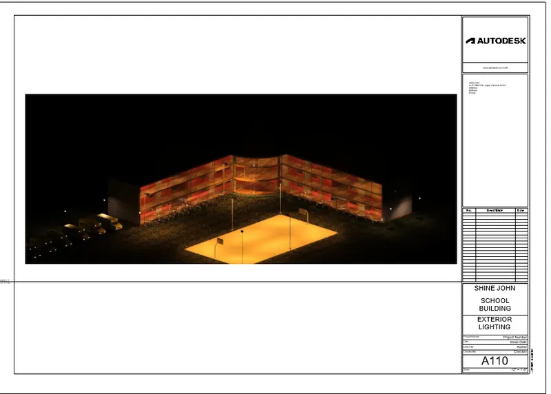
EXTERIOR LIGHTNG
PREVIEW
EXTERIOR SUN RENDERING
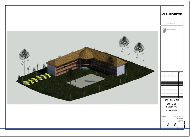
RESULT: The following rendering images are shared in the sheets is completed.
7)
AIM
To create the set of drawing sheets created and submit the drawings from the architecture and structure model.
INTRODUCTION
The set of drawings are created in revit software.
PROCEDURE
Open the architectural tab.
select the view in the tool bar.
select the sheets in the toolbar.
A sheet will appear drag the view which ever is needed.
TYPE CTRL +P to print the set of sheets in the drawing.
the files have been attached in the saved file.
RESULT: THE set of sheets are attached and saved in PDF is complted.