Creating Architectural and Structural model with 3D rendering using REVIT
1)
- I have chosen an office building for the project.
2)
The office building is planned to be constructed in commercial IT park area in Kochi.
Modelling requirements as per NBC-
Since, my building is an office building, it can be taken as a business building.
- The open space around the building shall not be less than 4.5m.
- Considering the type of construction as type 2 construction , the FAR value for the business building shall be taken as 2.9. The plot size is taken as 40mx70m i.e, 2800m2">m2m2 and individual floor area is 2000m2">m2m2. Hence, FAR value obtained is 2.14 which is within the prescribed limits as per NBC. `
- The width of the road abutting the building is taken as 9m (30').
- The maximum height of the building shall not exceed 1.5 times the width of road abutting plus the front open space. Building will consist of 3 floors each floor having a floor height of 3.6m. Hence, the entire floor height will be 10.8m, which is within the limits prescribed by NBC.
3)
Aim:
To create the following in a structural template:
a. Foundation – Isolated / Wall/Matt Foundation
b. Columns
c. Beams Connected to Columns
d. Roof Framing/ Truss
e. Floor / Decks
f. Floor Openings for Elevators and Stairs
Procedure:
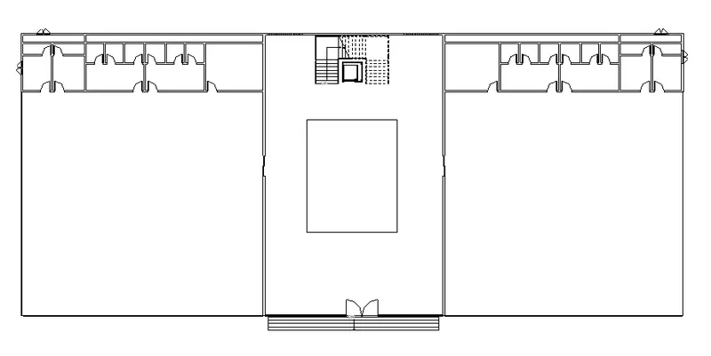
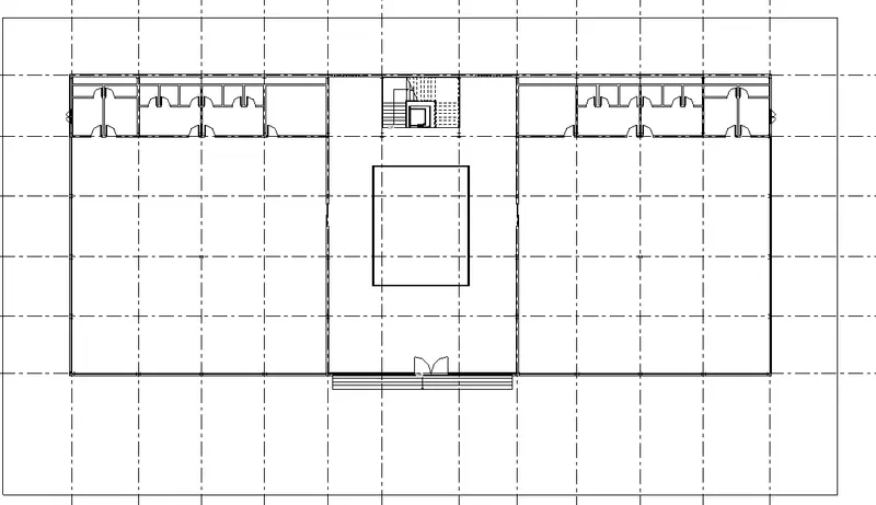
- Initially, open an architectural template and develop a rough plan of the office building as given below.
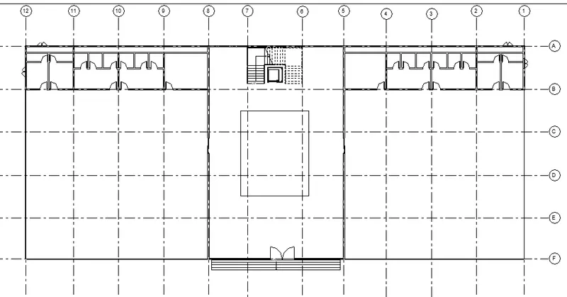
- Now, draw the grid lines in the architecture template as per the plan developed.
- Now, we have to copy ths grid lines to the structural template.
- For this, first we have to collaborate the project.
- Go to collaborate tab and select collaborate.
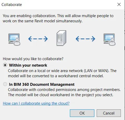
- Save the file as a central file.
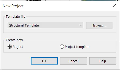
- Now, open the structural template in the revit software.
- Now, in the structural model ,go to collabrate tab and collaborate.
- Then save the file as central file.
- Now, go to insert option and insert the architecture model link into the structural model.
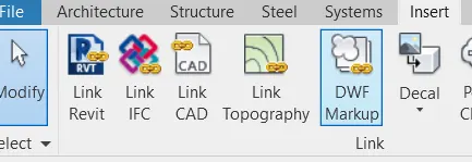
- Now, in the structural template, go to collaborate tab and choose copy/monitor to copy the grids.
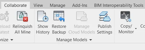
- Choose select link option and then select link in the window and the copy the grids both horizontal and vertical.
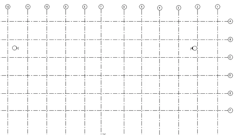
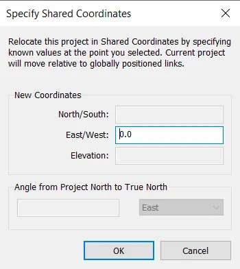
- Now, go to Manage tab, and select coordinates in that select specify coordinates at a point.
- Then, choose the horizontal grid an then specify the shared coordinate for north/south as 0.
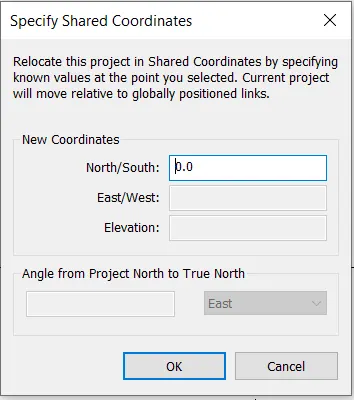
- Similarly specify the shared coordinates for the vertical grid too.
- Hence, the grids in the structural template is set.
a)
- Now, we have to place the footings and columns in the appropriate positions.
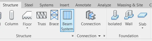
- For this go to structure tab of the revit and in that choose isolated footings.
- Now, place the footings at the required positions.
- The size of the footings is 1800x1200mm.
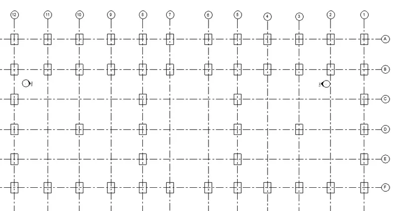
- These grids are then moved to the foundation level which is at a depth of 2.5m below the ground floor level.
b)
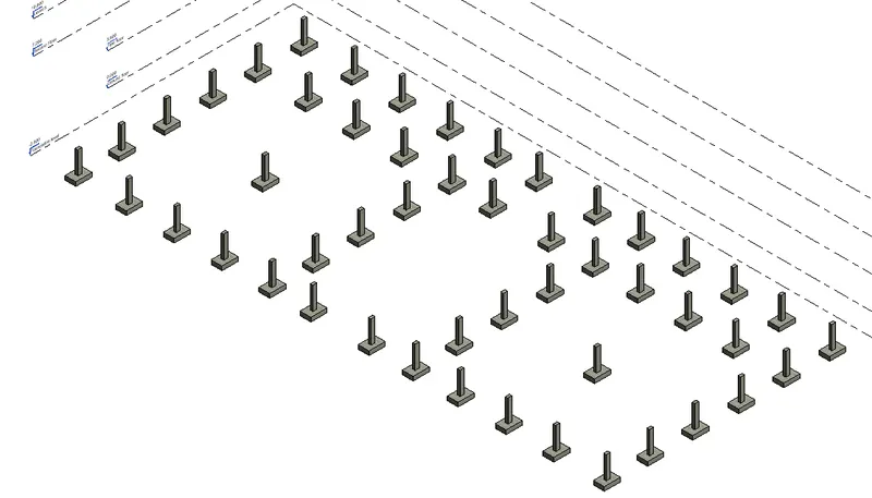
- Now, place the columns above each footings.

- 3D view is given below:
c)
- Next we have to place the grade beam at the ground floor level.
- For this go to structure tab and in that choose beams (concrete beam: 300x600mm).
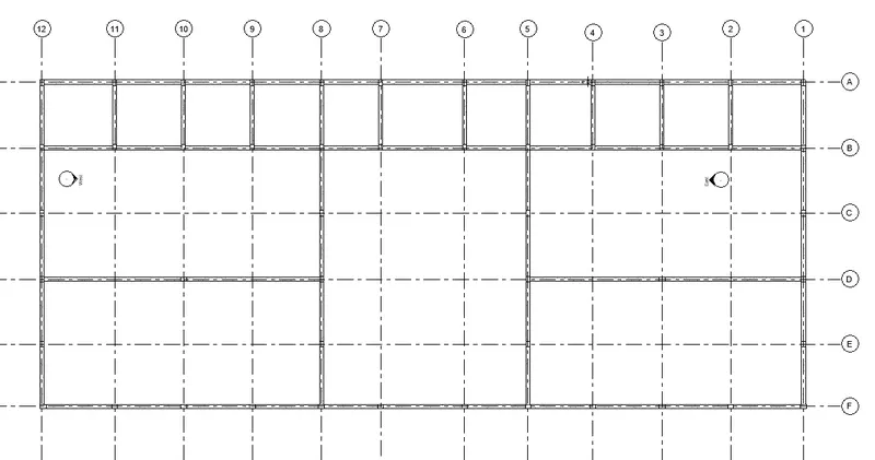
- 3D view is given below:
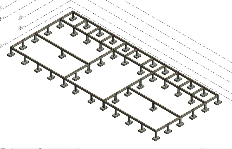

- Now we have to complete the framework of the building using this column beam structure.
- For the rest of the beams we have chosen: concrete beam 300x400mm.
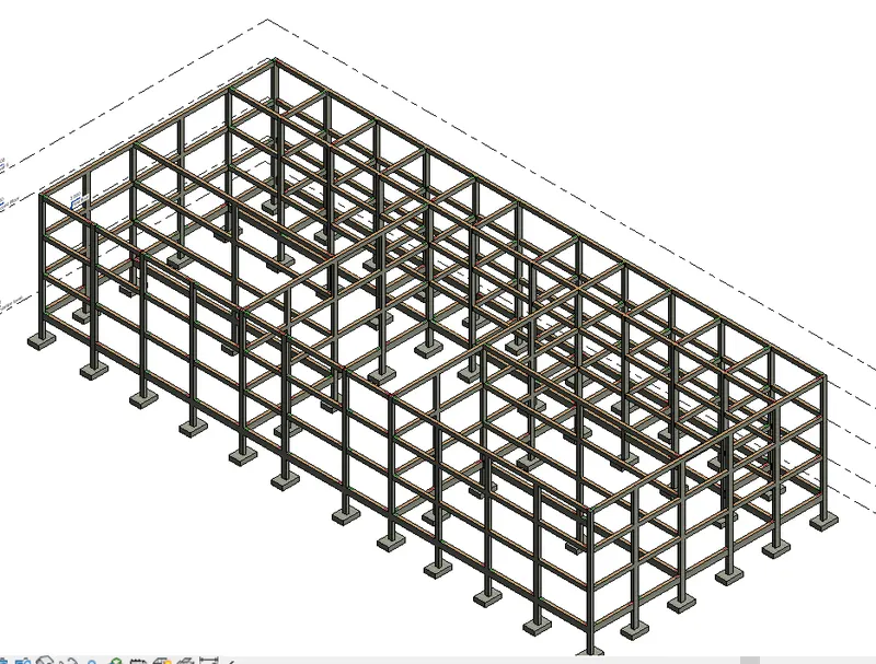
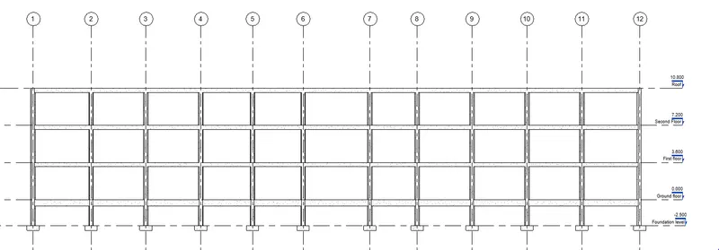
- Hence, the entire framework is completed.
d)
- Next we have to provide a roof for the structure.
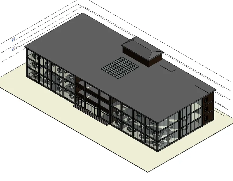
- Here, I have provided a skylight window at top centre portion.
- The remaining portion will be covered as a flat roof.
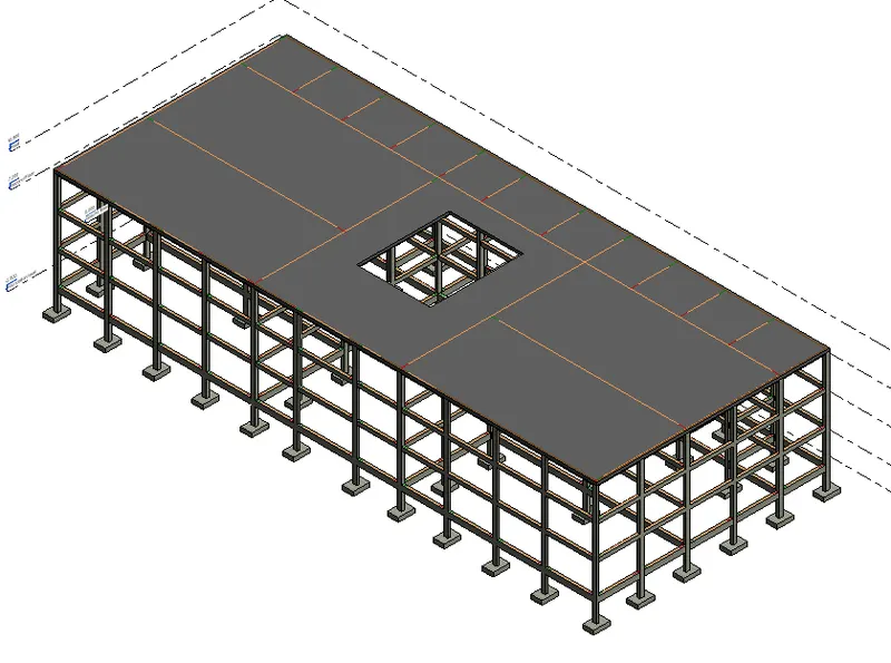
- The opening provided at the top is for skylight window. Hence, roof is completed.
e)
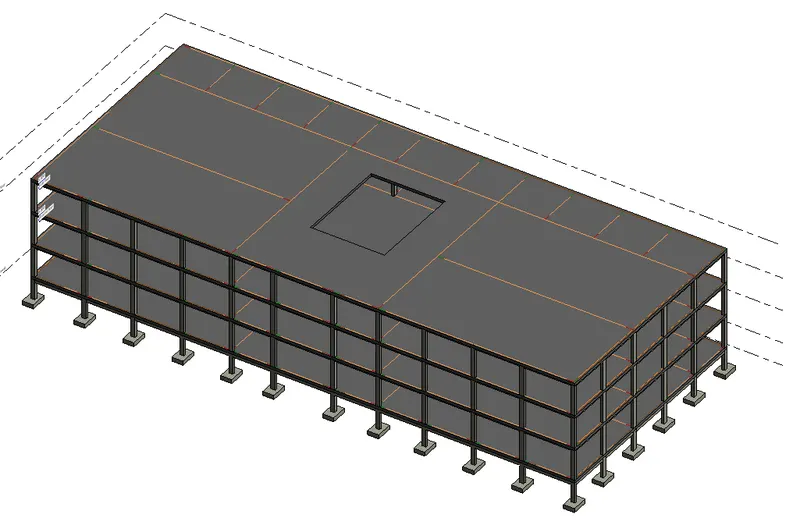
- Now, place the structural floor on each level.
- For this, go to structure tab --> floors.
- First draw the floor at ground floor level, then copy it to first, second and third floor.
f)
- Now, we have to provide floor opening for stairs and elevators.
- For this, go to architeture tab --> Shaft opening --> provide opening the at the required position.

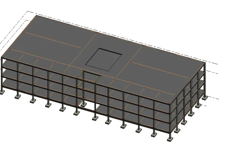
- Hence, the opening is also provided.
Result:
All the structural components have been provided in the structural model.
4)
Aim:
To include the following components in an architectural model:
a. Wall Layout with appropriate material and finishing
b. Exterior façade with fancy finish
c. Interior partition walls to size rooms
d. Components to add details to a room ( Desk, Chair, Lighting, Plumbing fixtures)
e. Add components such as stairs Elevators
f. Have at-least one side of the building with curtain walls and glass panels
g. Include interior and exterior lighting fixtures
h. Place proper topographic components from outside ( Trees, Parking, Plants) to add details to the model.
Procedure:
- Initially, we have to link the architectural and structural template.
- For this, first open architectural template and then insert the structural template into it.
- For this, go to insert tab --> revit links --> choose the links.
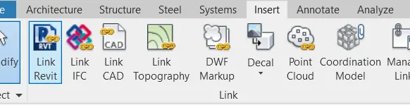
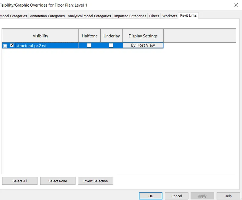
- Now, using the copy/monitor option we have to copy these elements to structural template.

- Hence, the architectural and structural model that are linked is given below:
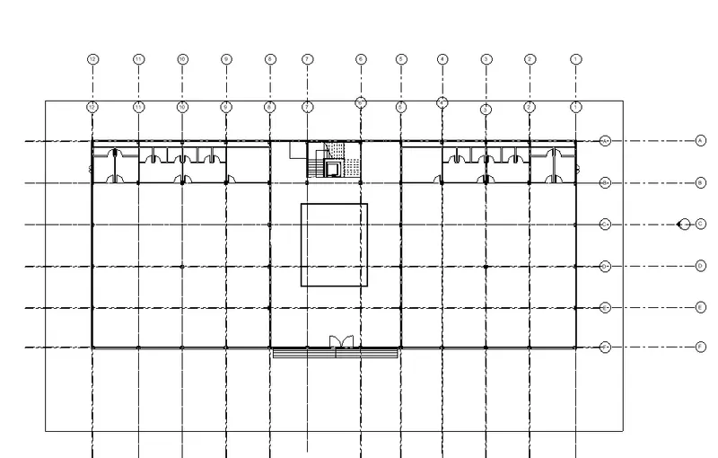
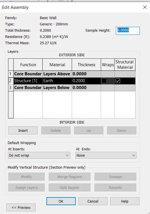
a) Wall layout has been developed. Wall thickness provided is 200mm. Now, we have to assign the material to the wall. Here, wall is availbale only in the one third portion rest is provided as curtain wall. Hence, wall material is needed to be assigned only at back portion.
Material provided for the wall is Earth.
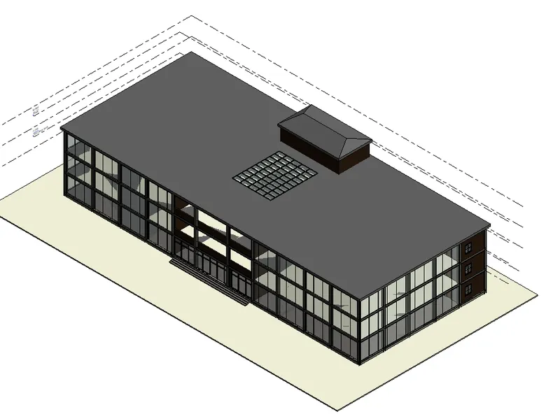
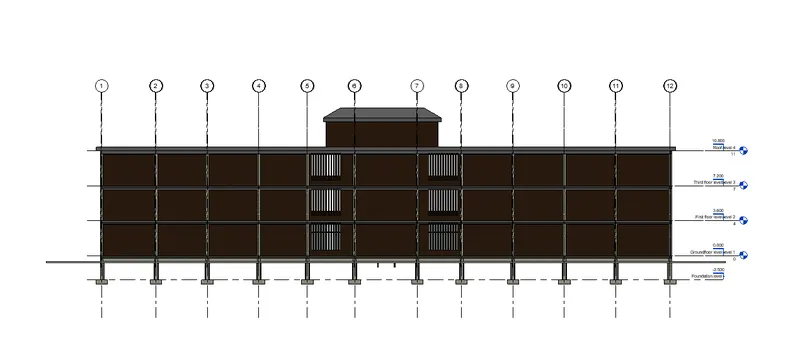
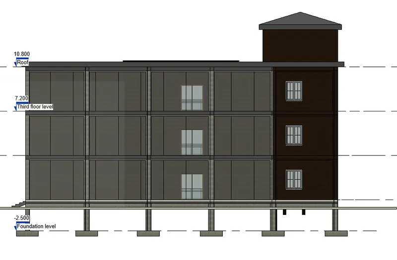
b) Exterior facade with fancy finish is also provided.
c) Interior partition walls to size rooms. Wall thickness provided is 138mm .
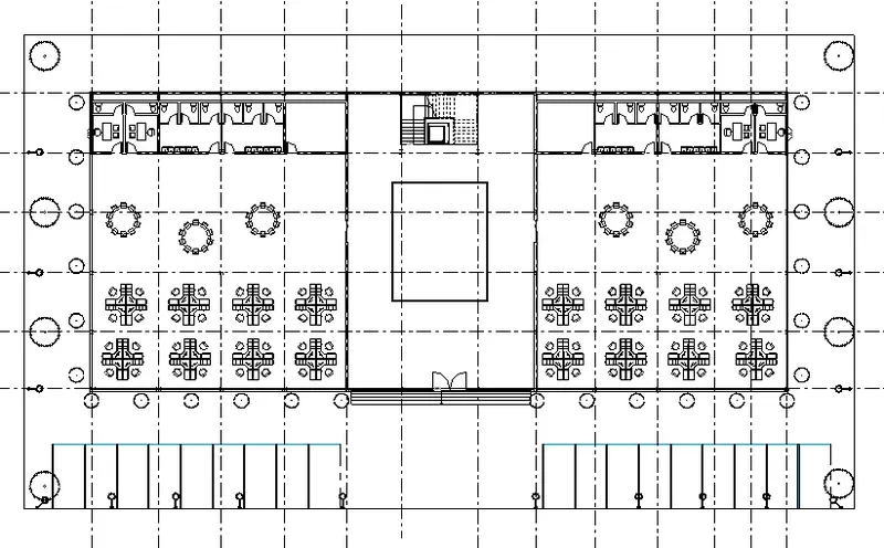
d) Components are to be added to add details to a room:
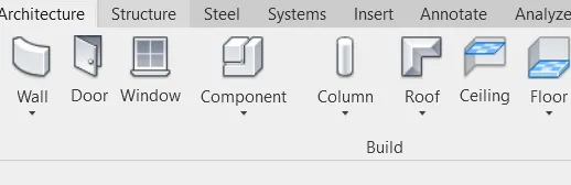
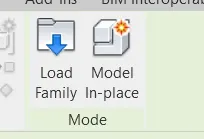
- This can be provided by going to architecture tab --> components --> load family --> and then place the required components at the required locations.
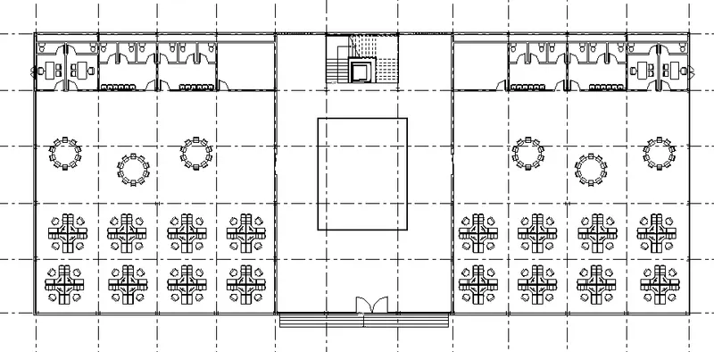
- Components have been placed in the ground floor. Similarly components can be place in the first and second floor also.
- This can be done by copying to the level 2 and 3.
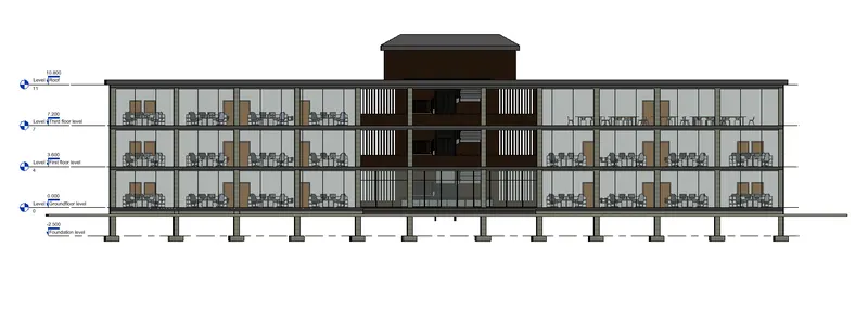
- In the third floor, right half is a cafeteria.
- Level1:
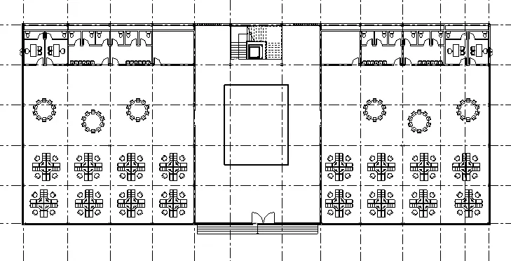
- Level 2:
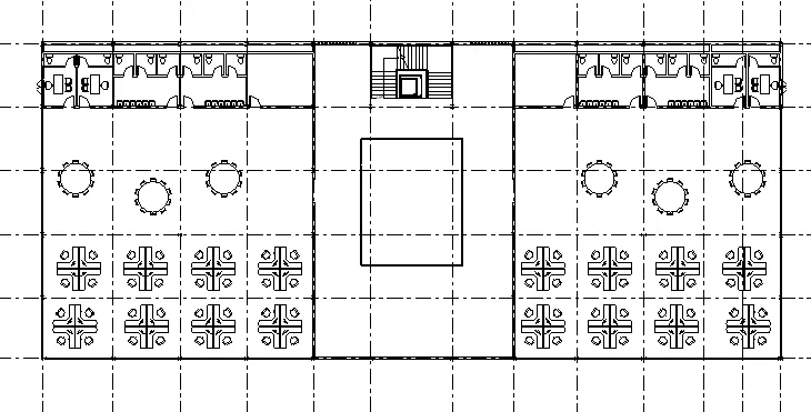
- Level 3:

- Level 4:
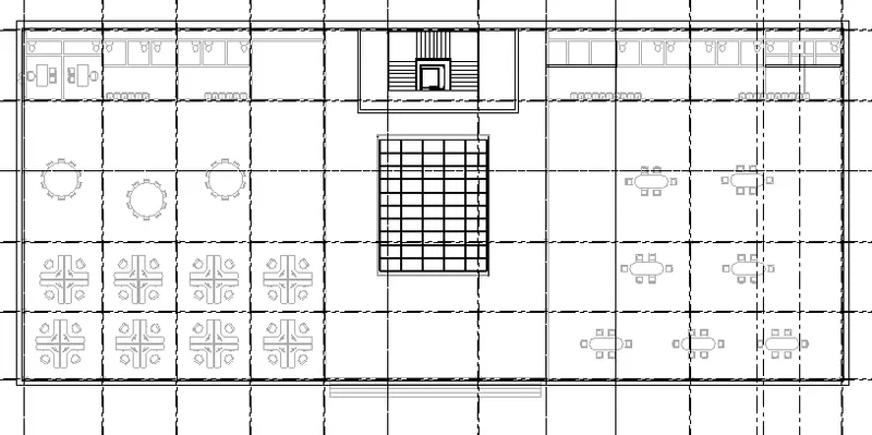
- Hence, all the components have been provided successfully.
e) Elevators and stairs have also been added to the plan: Stairs surrounding the elevator is included.
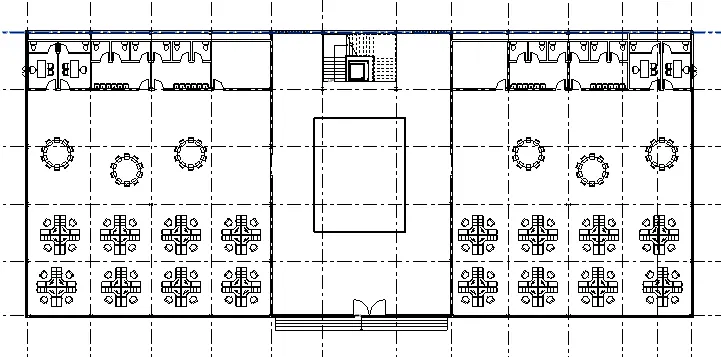
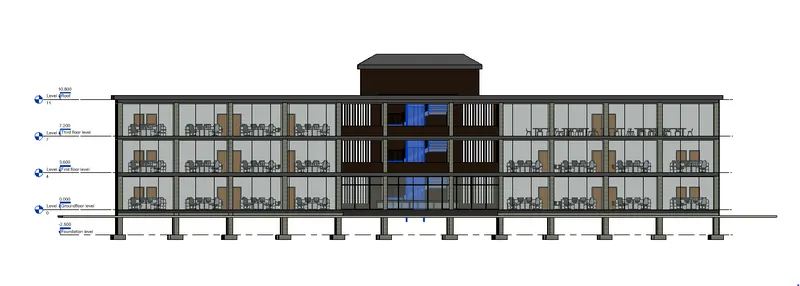
f) The front, east and west portion has been provided with storefront curtain wall.
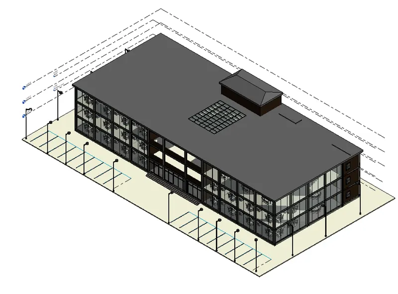
g) Interior and exterior lighting fixtures:
Street lights and parking space have been provided.
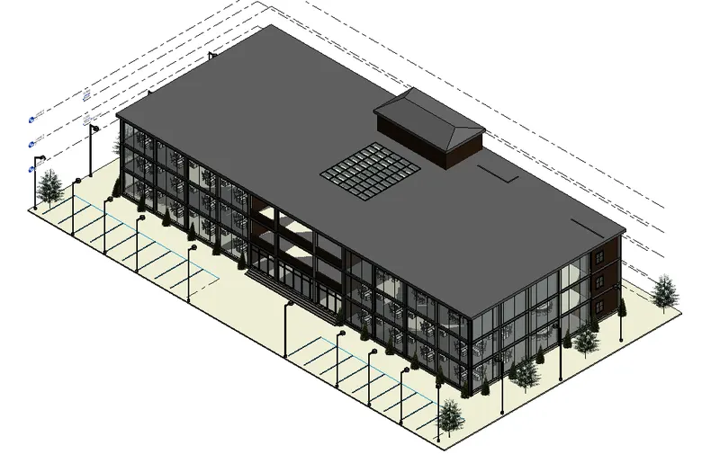
h) Now, other topographic components needed to be added:
For this, go to Architexture tab --> components --> load family --> select plantings and place shrubs and other plants.
Result:
- All the architectural components have been placed including parking area and geographic components like plants.
5)
Aim:
To provide the following in sheet templates:
a. Floor Plans with Annotations
b. Elevations
c. Sections
Procedure:
a)
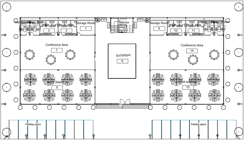
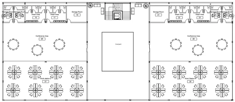
- Initially, provide the annotations to each level.
- Level 1
- Level 2
- Level 3:
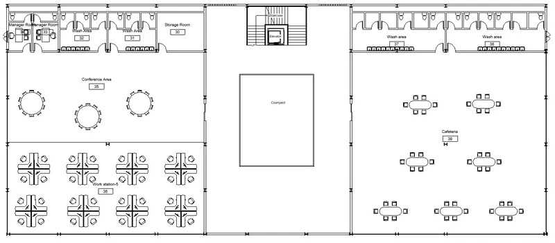
- Level 4:

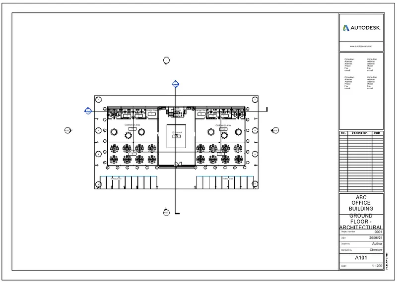
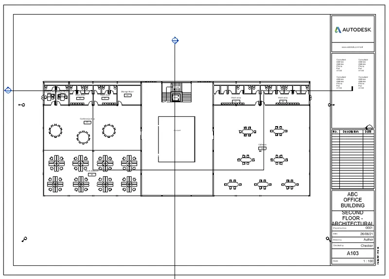
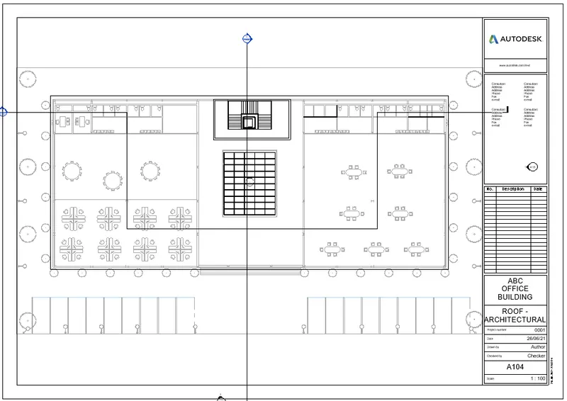
- Now, all these views are then added to the templates as follows:

- Structural floor plans:
- Ground floor level:
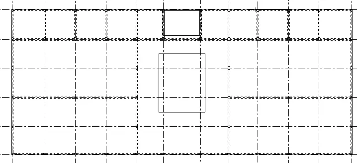
- First floor level:
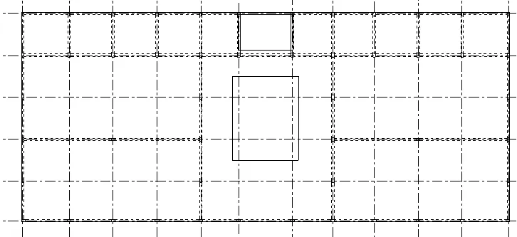
- Second floor level:
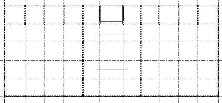
- Roof:
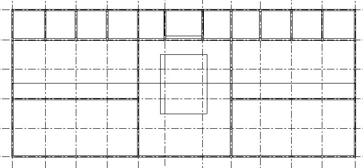
- Now, these are added to templates:
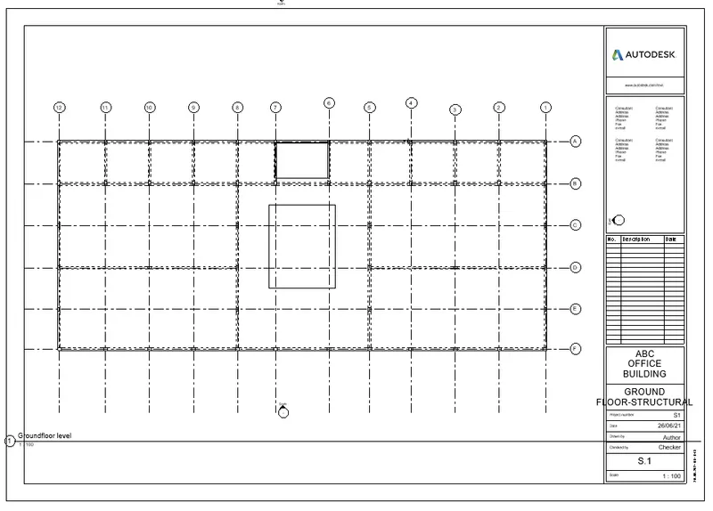
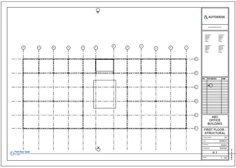
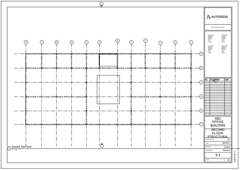
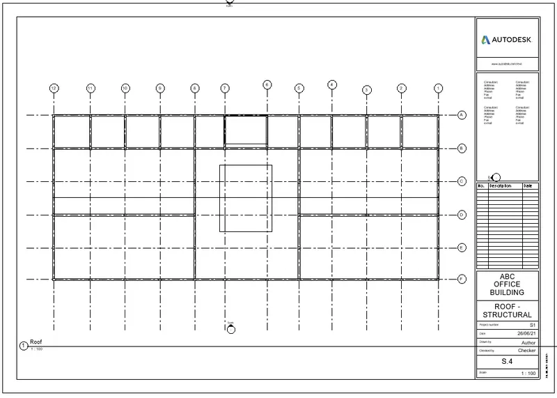
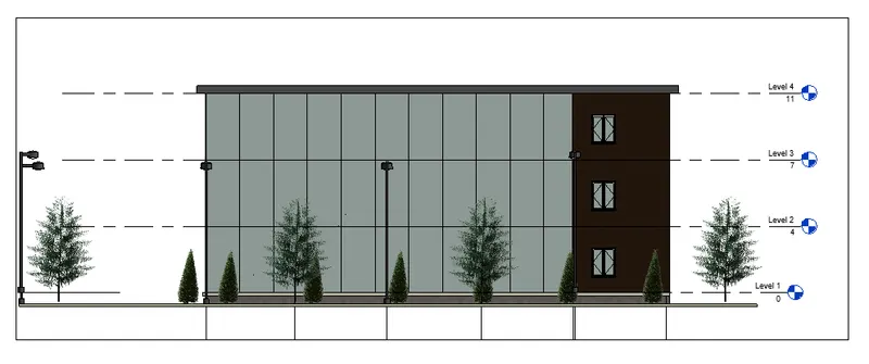
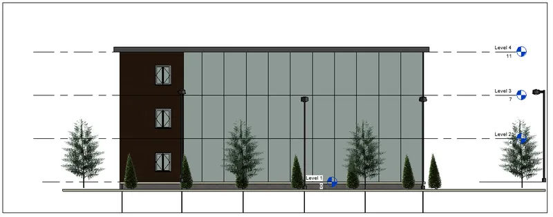
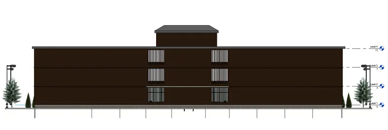
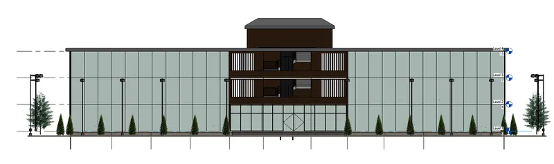
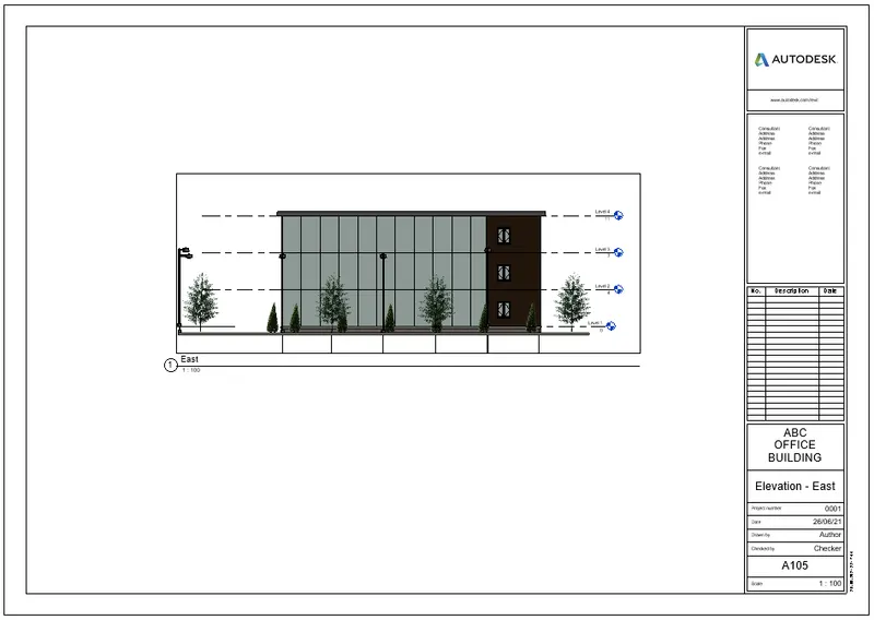
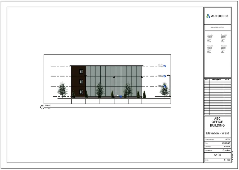
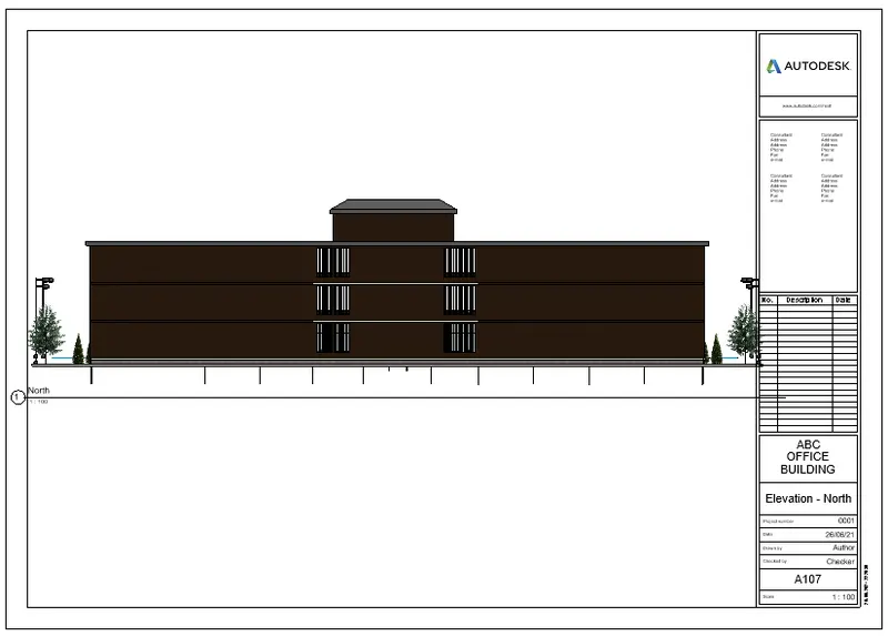
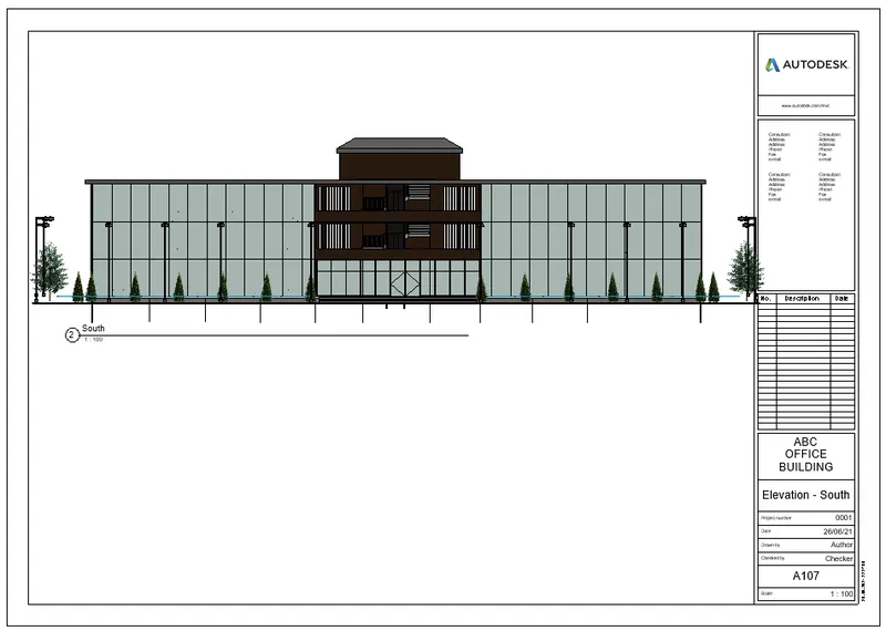
b) Elevations:
- East:
- West:
- North:
- South:
- Elevation templates:
c) Sections:
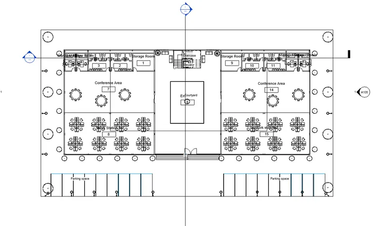
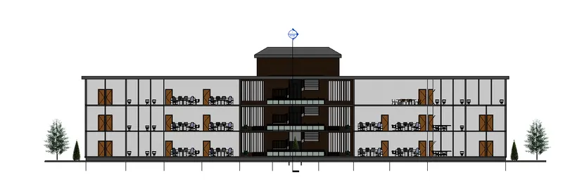
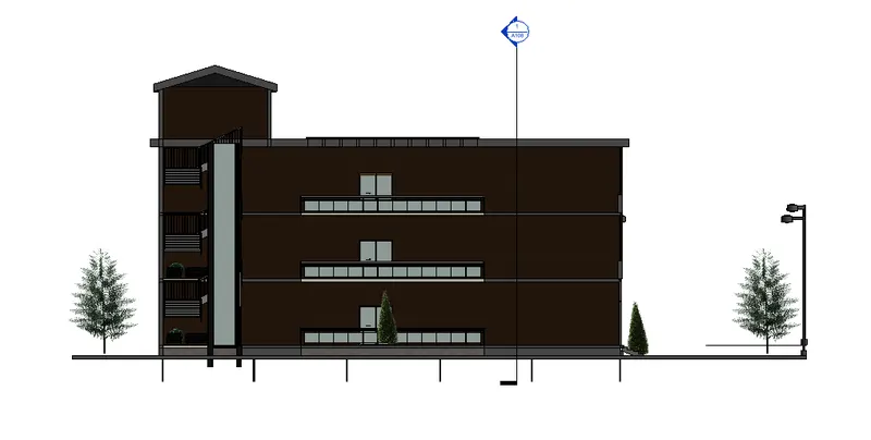
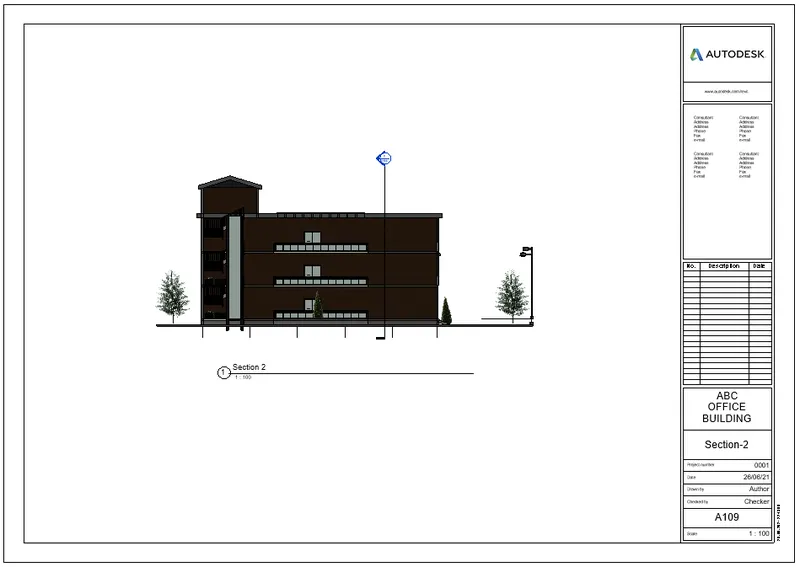
The two sections created are shown in the plan below:
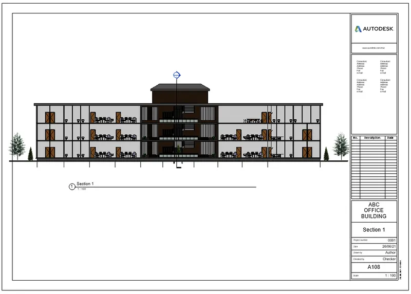
- Template sheets of the section are given below:
Result:
Hence, all the set of drawings are provided with appropriate sheet templates including the following:
a. Floor Plans with Annotations
b. Elevations
c. Sections
6)
Aim:
To create the rendered 3D images of the following and to include them in the templates:
a. Rendering from interior rooms
b. Rendering from out showing topographic features
c. Rendering through structural framing
Procedure:
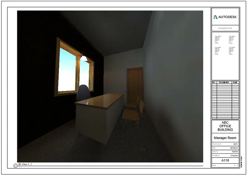
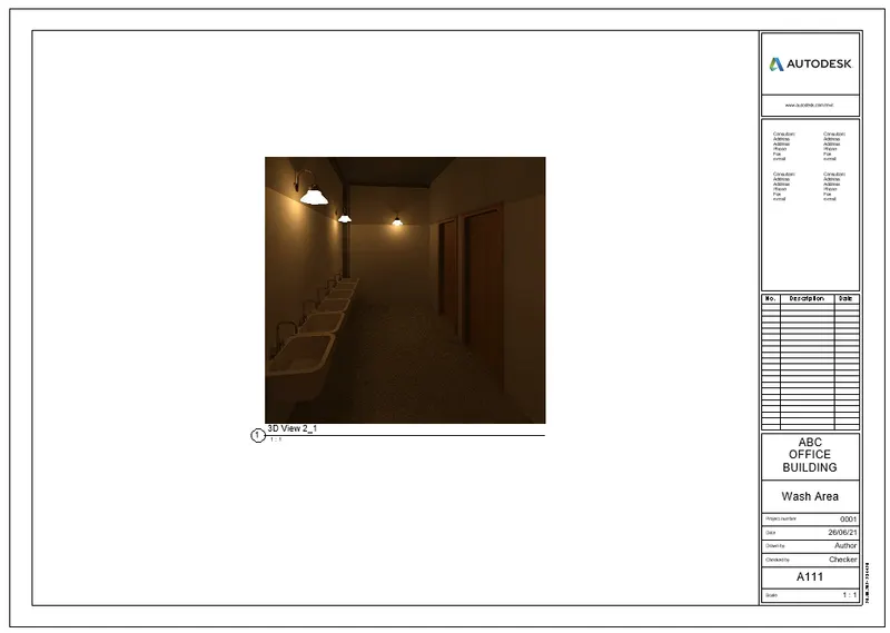
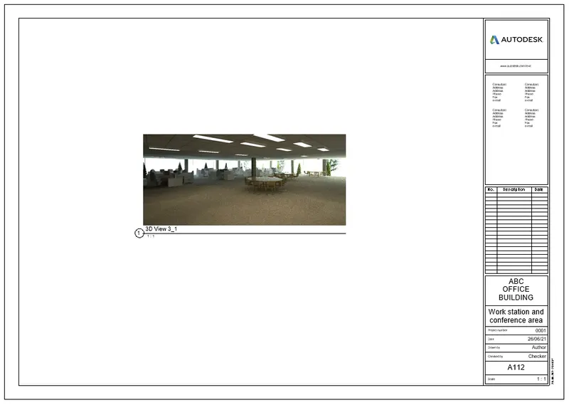
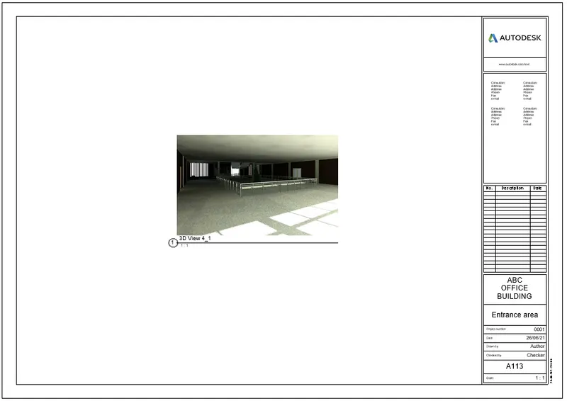
- Initially, create the 3D rendered image of different interior rooms:
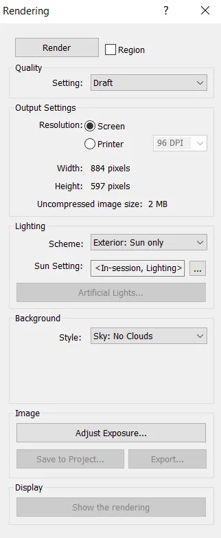
- To create the 3 D rendered image first go to view --> 3D view --> Camera.
- Then place the camera wherever required .
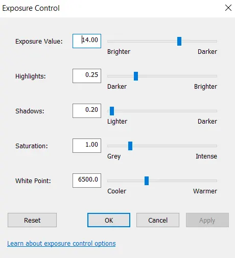
- Then in the view tab select render option to render the 3D image.
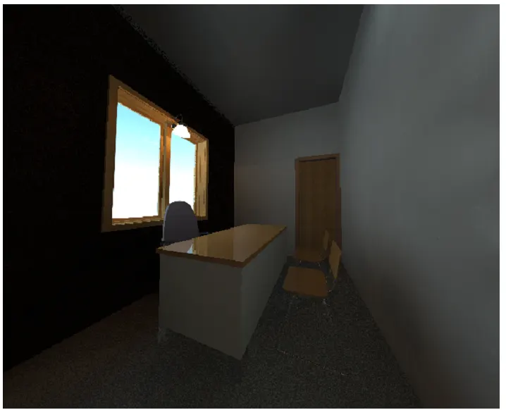
- Manager room:
- Wash area
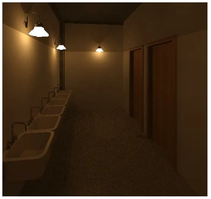
- Work station and conference area:
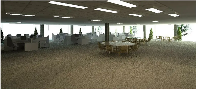
- Entrance area :
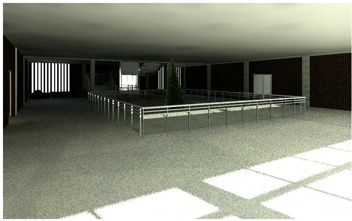
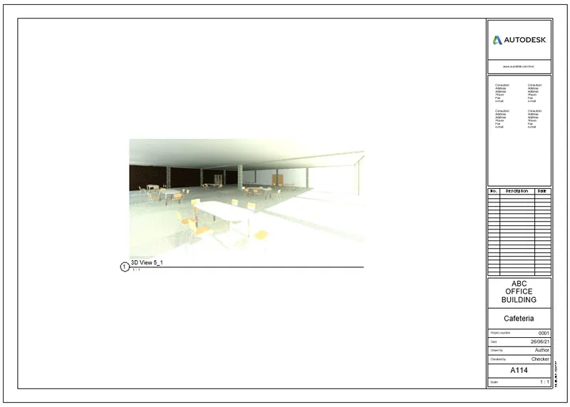
- Cafeteria:
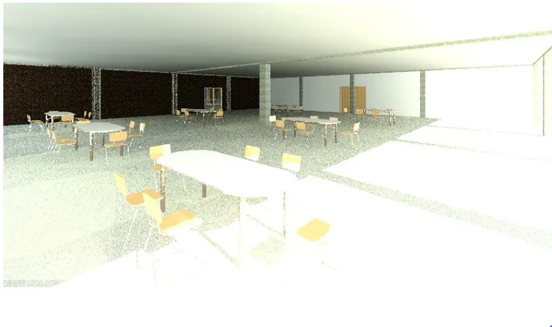
a) Rendered images of the interior rooms are changed to template sheets:
b) Rendering from out showing geographic features:
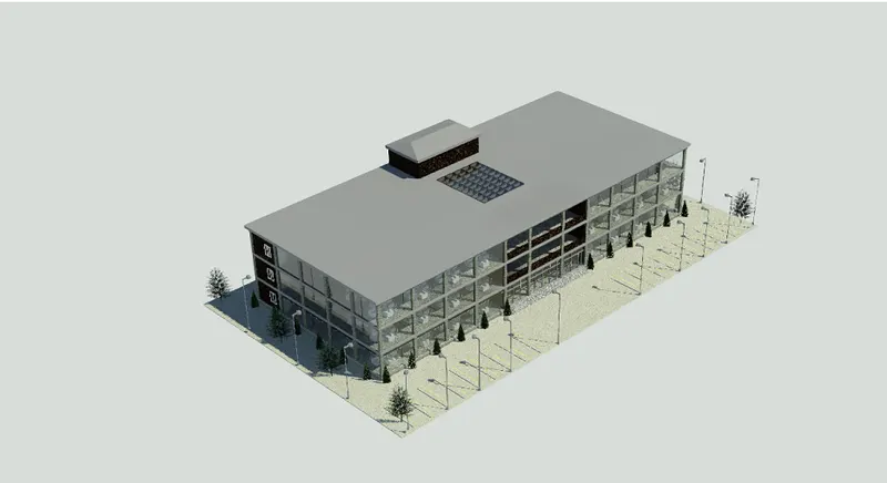
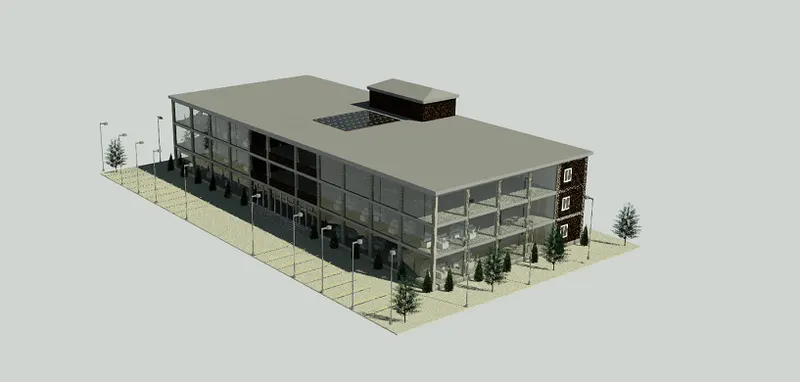
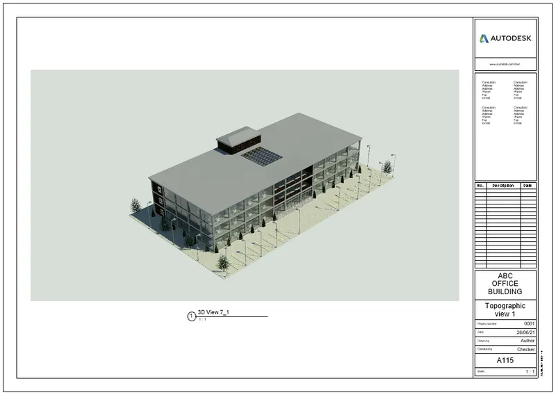
- These views are then added to template sheets:
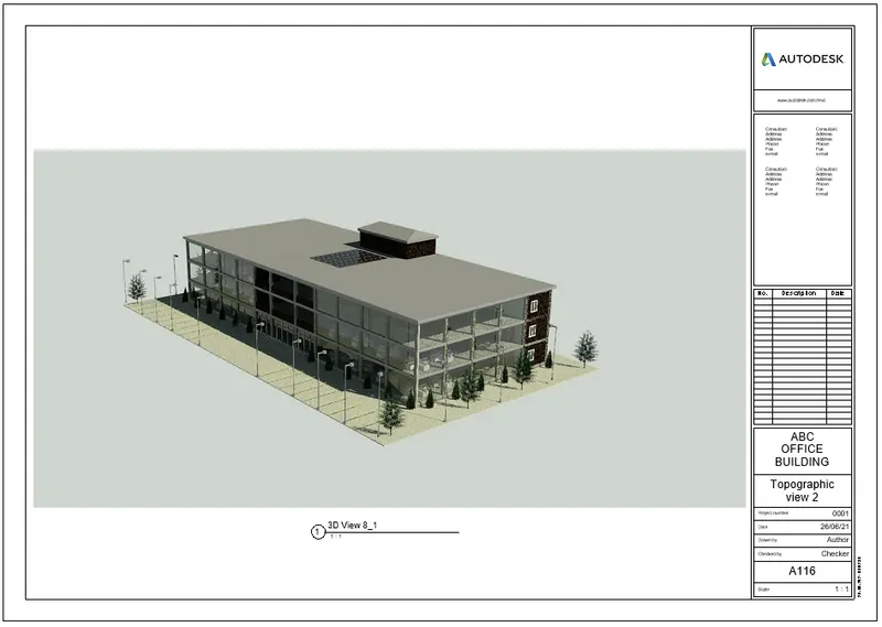
c) Rendering through structural framing:
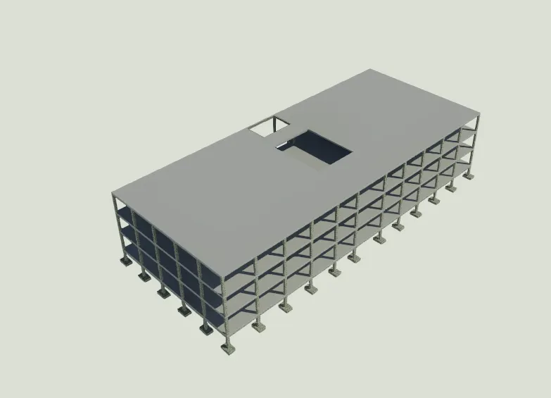
- Now, add it to template:
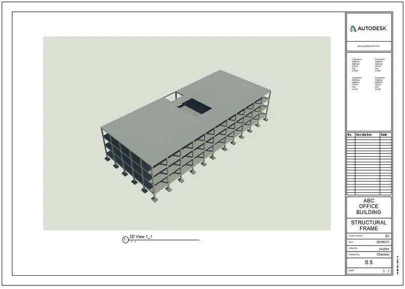
Result:
Hence, the rendered 3D images has been produced and are added to the templates.
7)
The different drawing templates can be printed. This can be done by going to the file menu in the top left corner of the revit window and in that choose print, then this window appears.
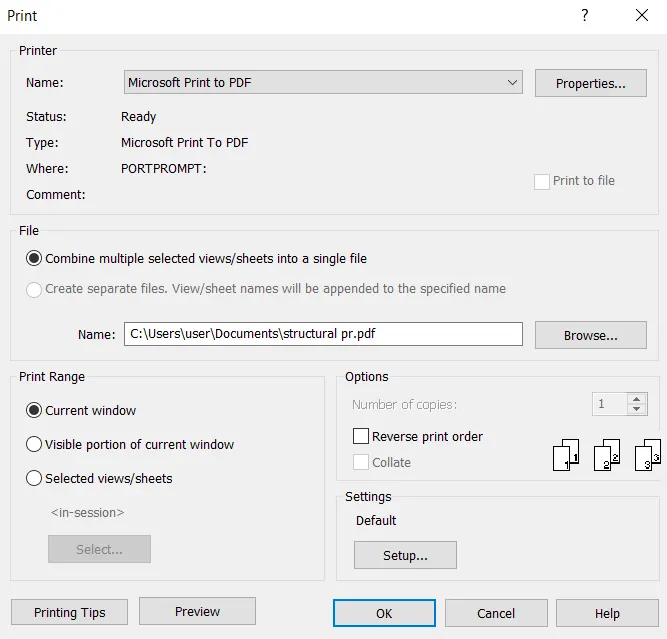
Hence, by following the procedures print can be taken.
Hence the entire 3D model combining both Architectural and structural template has been completed