Creating Architectural and Structural model with 3D rendering using REVIT
1) Select the type of structure you want to build from one of the three below:
a. Multi-Unit Residential Apartment
b. Office Buildings
c. School
Ans: I am going to build a model of Multi-Unit Residential Apartment.
2) Assume reasonable assumptions for geographic and location details for your project modeling. Based on assumptions and type of structure selected identify the modeling requirements from NBC
Ans: I am selecting a plain area with normal wind flow, moderate temperature and normal rainfall for my project.
- It will be in a Primary residential Zone (R-1).
- I am assuming the width of the road in front of the structure to be 21m.
- As the height of my structure will be 18.3m it should have side and rear open spaces of 7m.
- Its whole ground floor will be for parking and the flats will acquire floors from first to fourth.
- The height of all rooms for human habitation shall not be less than 2.75 m measured from the surface of the floor to the lowest point of the ceiling.
- The area of habitable room shall not be less than 9.5 m2, where there is only one room with a minimum width of 2.4 m. Where there are two rooms, one of these shall not be less than 9.5 m2 and the other not less than 7.5 m2, with a minimum width of 2.1 m.
- The height of a kitchen measured from the surface of the floor to the lowest point in the ceiling (bottom slab) shall not be less than 2.75 m, except for the portion to accommodate floor trap of the upper floor.
- The area of a kitchen where separate dining area is provided, shall be not less than 5.0 m2 with a minimum width of 1.8 m. Where there is a separate store, the area of the kitchen may be reduced to 4.5 m2. A kitchen, which is intended for use as a dining area also, shall have a floor area of not less than 7.5 m2 with a minimum width of 2.1 m.
- Every room to be used as kitchen shall have:
- unless separately provided in a pantry, means for the washing of kitchen utensils which shall lead directly or through a sink to a grated and trapped connection to the wastepipe;
- an impermeable floor;
- a flue, if found necessary; and
- a window or ventilator
- The height of a bathroom or water-closet measured from the surface of the floor to the lowest point in the ceiling (bottom of slab) shall not be less than 2.1 m.
- The area of a bathroom shall not be less than 1.8 m2 with a minimum width of 1.2 m. The floor area of water-closet shall be 1.1 m2 with a minimum width of 0.9 m. If bath and water-closet are combined, its floor area shall not be less than 2.8 m2 with a minimum width of 1.2 m.
- Every bathroom or water-closet shall:
- a) be so situated that at least one of its walls shall open to external air;
- b) not be directly over or under any room other than another water-closet, washing place, bath or terrace, unless it has a water-tight floor;
- c) have the platform or seat made of water-tight non-absorbent material;
- d) be enclosed by walls or partitions and the surface of every such wall or partition shall be finished with a smooth impervious material to a height of not less than 1 m above the floor of such a room;
- e) be provided with an impervious floor covering, sloping towards the drain with a suitable grade and not towards VERANDAH or any other room; and
- f) have a window or ventilator, opening to a shaft or open space, of area not less than 0.3 m2 with side not less than 0.3 m.
3) Using the structural model, include the following components based on the type of structure selected
a. Foundation – Isolated / Wall/Matt Foundation
b. Columns
c. Beams Connected to Columns
d. Roof Framing/ Truss
e. Floor / Decks
f. Floor Openings for Elevators and Stairs
Ans:
Using the structural model, include the following components based on the type of structure selected
a. Foundation – Isolated / Wall/Matt Foundation
b. Columns
c. Beams Connected to Columns
d. Roof Framing/ Truss
e. Floor / Decks
f. Floor Openings for Elevators and Stairs
PROCEDURE:
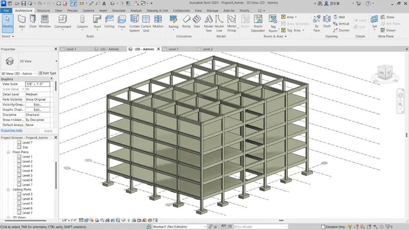
- open Revit and make horizontal and vertical grids at spacing of 20'.
- go to the elevation and increase the number of levels up to roof and change their names.
- select column from ribbon and place the columns at intersection of grids as shown.
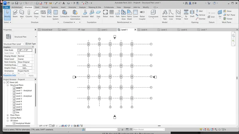
- place another column on the grid intersection from ground floor to first floor.
- now select beam from the ribbon and connect this beam to different columns as shown.
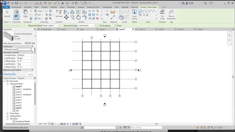
- now go to isolated option from the ribbon and place them on the different columns as shown
- select the entire figure and go to the copy option and assign them to first floor and second floor.
- now go to the Floor option and change the view to ground floor and select points and make a loop and assign them to the floors.
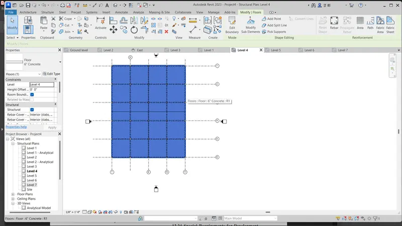
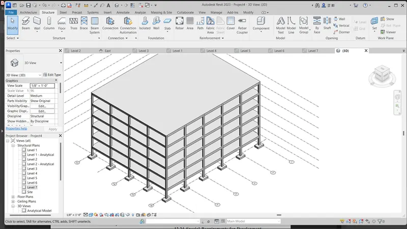
- Go to floor plan first floor.
- Select shaft from the structure tab.
- Select the part where we want the shaft to be, for the lift and stairs.
- Select the base constraint as the ground floor and the top constraint as the top floor.
- Draw the desired dimension rectangle.
- Click on the tick mark to create the shaft for the lift and stairs.
4) Using the architectural model, include the following components based on the type of structure selected
- Wall Layout with appropriate material and finishing
- Exterior façade with fancy finish
- Interior partition walls to size rooms
- Components to add details to a room ( Desk, Chair, Lighting, Plumbing fixtures)
- Add components such as stairs Elevators
- Have at-least one side of the building with curtain walls and glass panels
- Include interior and exterior lighting fixtures
- Place proper topographic components from outside ( Trees, Parking, Plants) to add details to the model
Ans:
Procedure:
- with the same grids drawn in the previous plan draw a wall along the boundary.
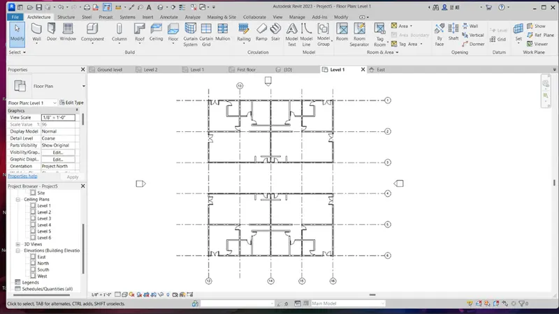
- draw the interior partitions and place the required furniture and components in the plan and change the view to 3d.
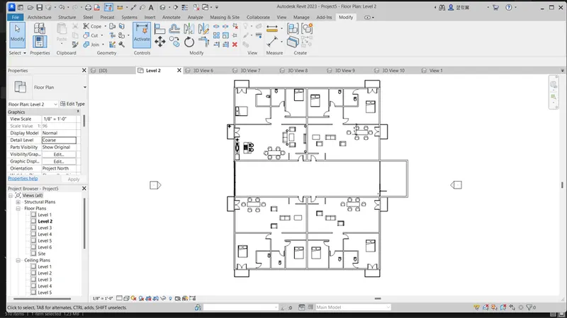
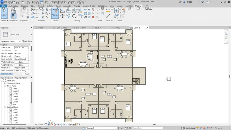
- draw the roof by making a rectangle along all the sides of second floor.
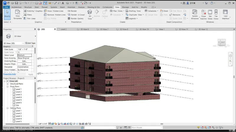
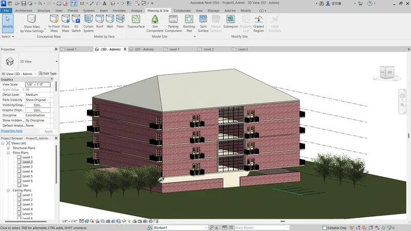
- Go to massing and site and form a topography using the toposurface option.
- Add plantations and parking (if required).
5) Provide a set of drawings in an architectural and structural model to list the following details with categories and appropriate sheet templates included
a. Floor Plans with Annotations
b. Elevations
c. Sections
Ans:
Procedure:
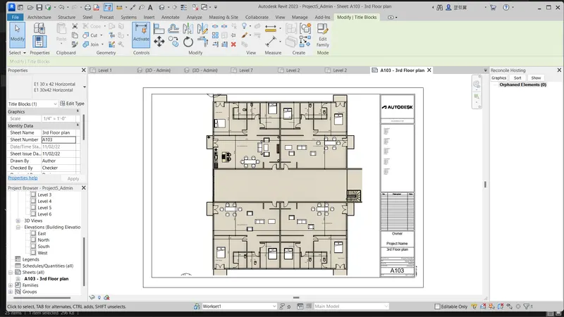
- First go to each floor plan individually.
- Go to view tab.
- Click on Sheets.
- It will open a title block template.
- Right click on the sheet in the project browser to rename the sheet.
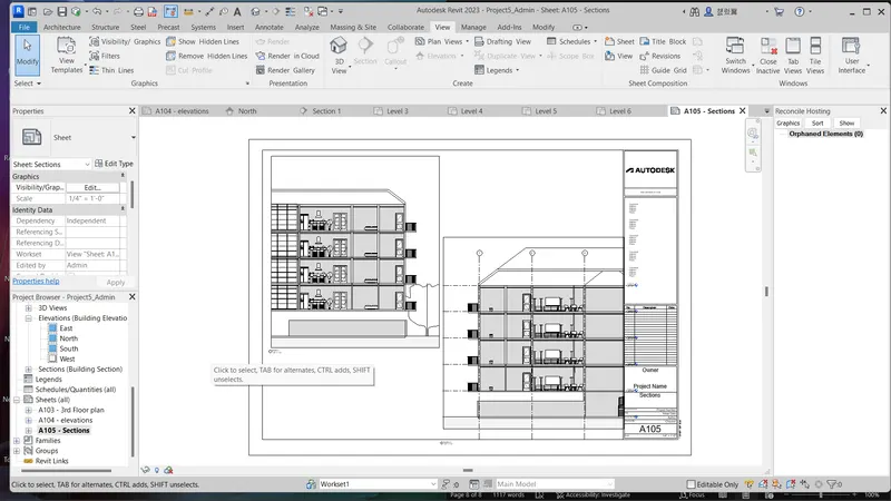
- Rename the sheets to floor plans, elevation and section.
- Then right click on each sheet to add the views.
- Select the view that has to be added from the list that appears after clicking on the add view option.
- And add the views to the respective sheets.
- Set the suitable scale.
- Click on the crop view and crop region option from the properties tab to crop the viewport to fit the size of the title box.
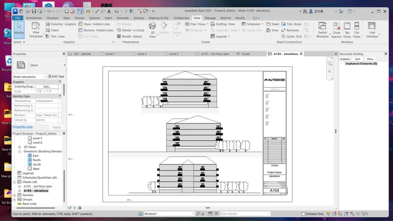
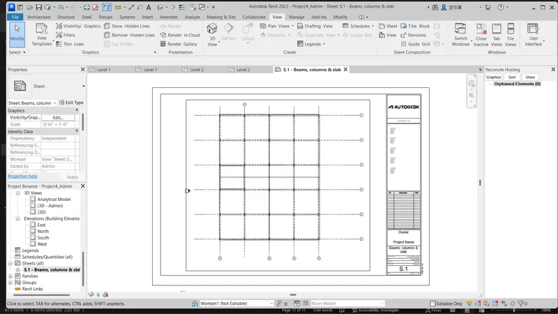
- The sheets after adding the views will appear as shown below:
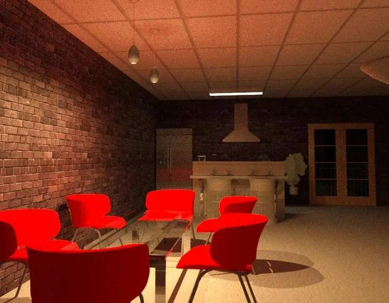
6) Using the Rendering settings, Render images of the 3D model produced and include the rendered images to the drawing sheets
a. Rendering from interior rooms
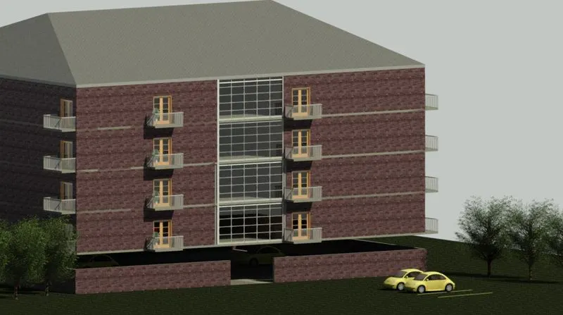
b. Rendering from out showing topographic features
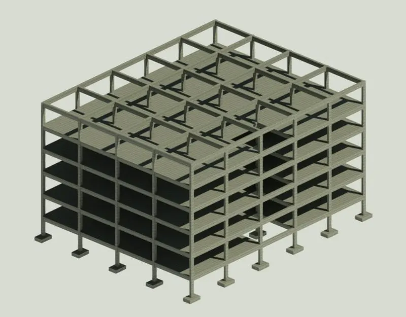
c. Rendering through structural framing
Ans:
Procedure:
- For renders of interiors first go to the floor plan of any floor.
- Click on the view tab and select camera from the 3d view drop down menu.
- Then place the camera and point the cursor towards the direction of which we want the render of.
- Click on render.
- Edit the settings accordingly, like the lighting scheme, in case of interior rendering for night view select only artificial to render and for day view sun only or sun and artificial.
- For renders of exterior select the 3dview and click on render.
- To insert image as background, in the render tab background section click on the style drop down menu.
- And insert the desired image.
- In the lighting scheme select sun only.
- Click on render.
- The renders will be as follows:
7) Print the set of drawing sheets created and submit the drawings from the architecture and structure model
ans:
Procedure:
* To print the sheets click on the print icon on the top left corner of the revit window.
In the dialogue box select selected view/sheets in the print range section and click ok.
Then select the sheets to print from the list.
Then click on print.