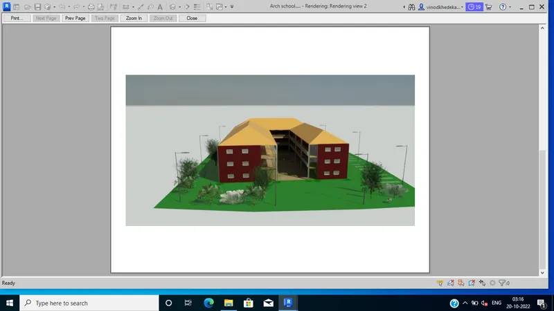
Creating Architectural and Structural model with 3D rendering using REVIT
PROJECT 2:-
Creating Architectural and Structural model with 3D rendering using REVIT
1) Select the type of structure you want to build from one of the three below:
a. Multi-Unit Residential Apartment
b. Office Buildings
c. School
Answer:- I have selected School Building
2) Assume reasonable assumptions for geographic and location details for your project modeling. Based on assumptions and type of structure selected identify the modeling requirements from NBC
Answer:- Assumption for the geographic and location details for my project are as follows:
- My building is constructed in plain areas (Geography)
- My building is constructed in commercial area, Gondpipari, Maharashtra, India
3) Using the structural model, include the following components based on the type of structure selected
a. Foundation – Isolated / Wall/Matt Foundation
b. Columns
c. Beams Connected to Columns
d. Roof Framing/ Truss
e. Floor / Decks
f. Floor Openings for Elevators and Stairs
Procedure:-
Step 1:
- Open Revit software
- Click on > New from home page
- One dialogue box will be open
- Select Structural template
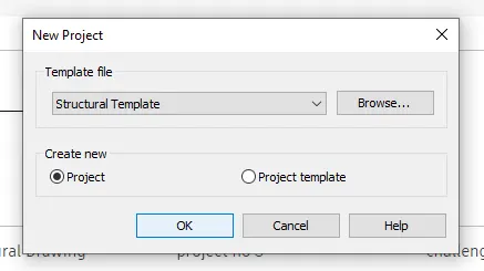
- Click > ok
Step 2:
- Click > file
- Click > save
- One dialogue box will open
- Select file name > School structural
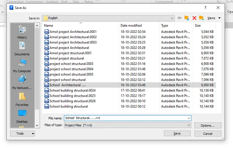
- Click save
Step 3:
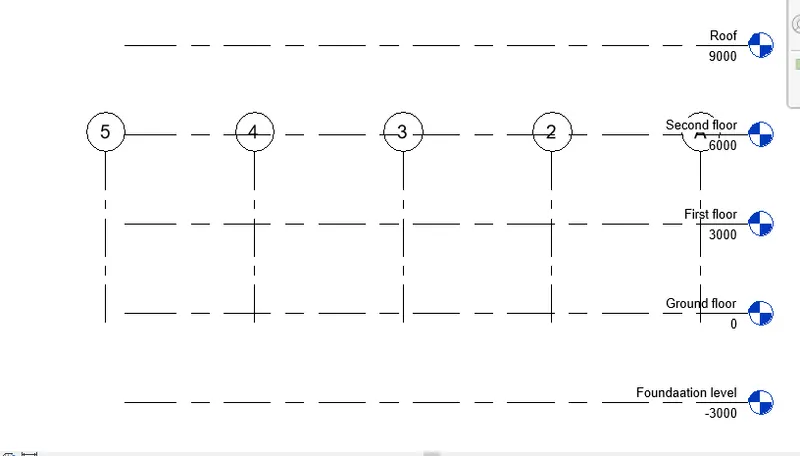
- Go to the structure tab
- Click on levels
- Provide levels as shown below
Step 4:
- Go to the structure tab
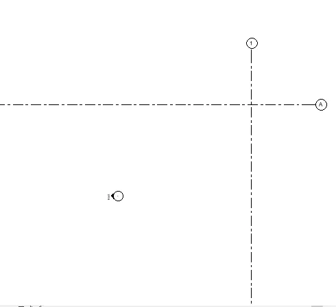
- Click > grids
- Provide horizontal as well as vertical grids as shown below
- Renamed the grids
- Vertical as > 1
- Horizontal as > A
Step 5:
- Go to the manage tab
- Click on project location
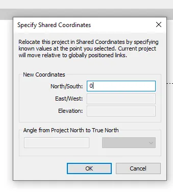
- Select > “specify coordinates at a point” from dropdown
- Select horizontal line
- One dialogue box will be open
- Set North/South as > 0
- Click ok
- Go to the manage tab
- Click on project location
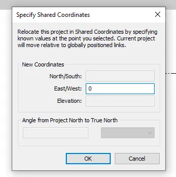
- Select > “specify coordinates at a point” from dropdown
- Select horizontal line
- One dialogue box will be open
- Set East/West as > 0
- Click ok
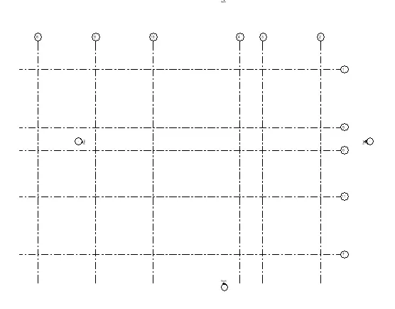
- Draw all the grids as per the requirements
Step 6:
- To provide footing
- Go to structure tab
- Select the Isolated footing
- Click on at grids
- Select all the grids
- Click on > finish
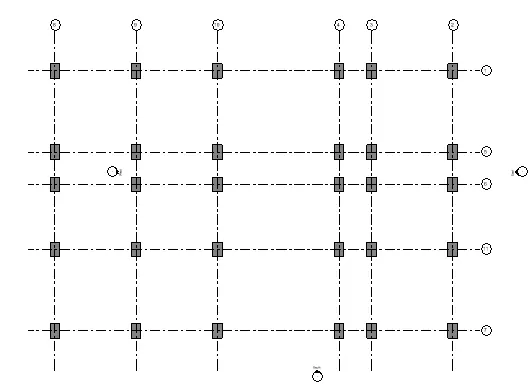
Step 7:
- To provide the columns
- Go to the structure tab
- Click on > column
- Select proper size of the column
- Click on > at grids
- Select all the grids
- Click on finish
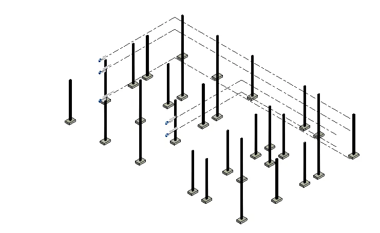
Step 8:
- To provide the Beams
- Go to the structure tab
- Select > Beams
- Select proper size
- Provide the beam at suitable place
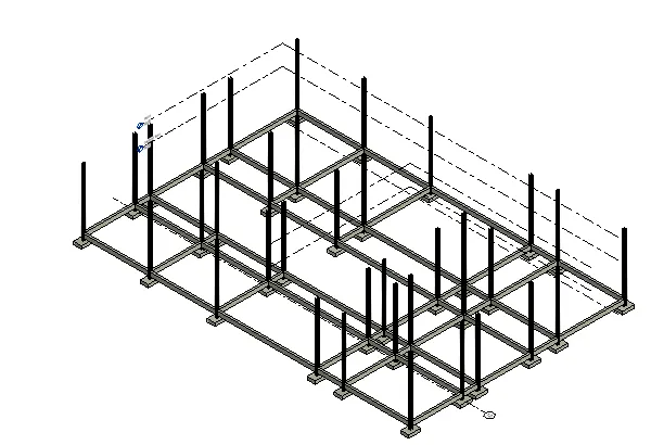
- simillarly create the beams for another levels as per requirements
Step 9:
- To provide the floor
- Go to the structure tab
- Select > floor
- Select type of floor
- Select boundary
- Provide the floors at all levels as shown below
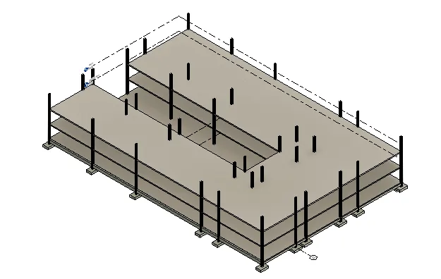
Step 10:
- To provide the shaft opening for the stairs
- Go to the structure tab
- Click on shaft
- Click on rectangle to draw the shaft opening
- Create boundary for the shaft opening
- Click on finish
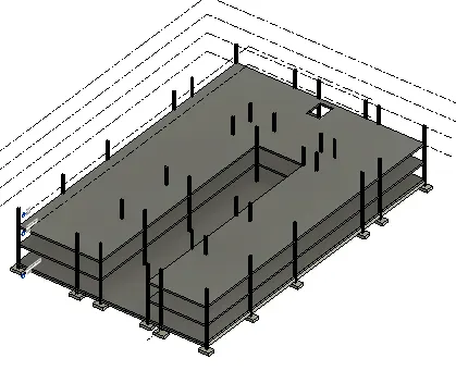
Step 11:
- To provide the Roof
- Go to the Architecture tab
- Click on > Roof by footprint
- Create boundary for the roof
- Click on finish
- To see the roof in the structural model
- Go to the view tab
- Click on Visibility/graphics setting
- Checkmark to the roof
- Click > ok
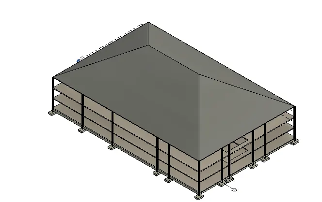
- After creating the roof , whenever you want to change the roof then you can edit the roof
Result :-
creating Footings and columns
Creating Beams
creating Floor
shaft poening
4) Using the architectural model, include the following components based on the type of structure selected
a. Wall Layout with appropriate material and finishing
b. Exterior façade with fancy finish
c. Interior partition walls to size rooms
d. Components to add details to a room ( Desk, Chair, Lighting, Plumbing fixtures)
e. Add components such as stairs Elevators
f. Have at-least one side of the building with curtain walls and glass panels
g. Include interior and exterior lighting fixtures
h. Place proper topographic components from outside ( Trees, Parking, Plants) to add details to the models
Procedure:-
Step 1:
- Open Revit software
- Click on > New from home page
- One dialogue box will be open
- Select Architectural template
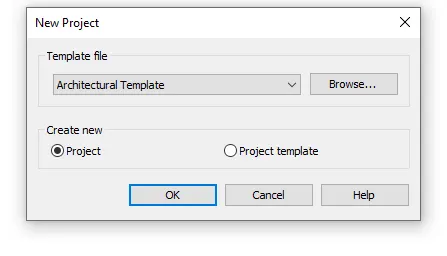
- Click > ok
Step 2:
- Click > file
- Click > save
- One dialogue box will open
- Select file name > School Architectural
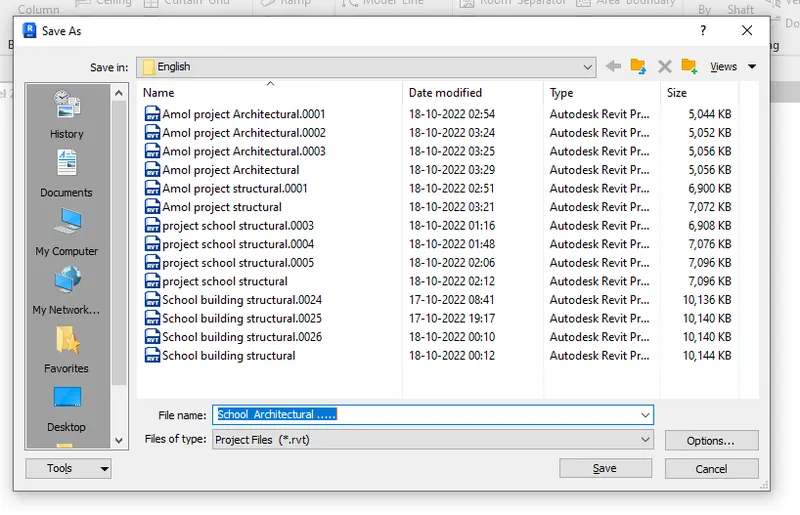
- Click save
Step 3:
- Go to the Architectural tab
- Click > grids
- Provide horizontal as well as vertical grids as shown below
- Renamed the grids
- Vertical as > 1
- Horizontal as > A
Step 4:
- Go to the manage tab
- Click on project location
- Select > “specify coordinates at a point” from dropdown
- Select horizontal line
- One dialogue box will be open
- Set North/South as > 0'
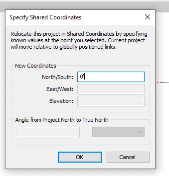
- Click ok
- Go to the manage tab
- Click on project location
- Select > “specify coordinates at a point” from dropdown
- Select vertical line
- One dialogue box will be open
- Set East/West as > 0
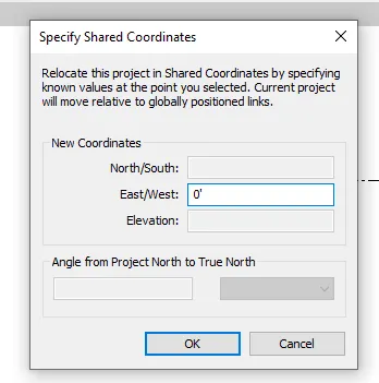
- Click ok
Step 5:
- Go to the manage tab
- Click on manage link
- Click on> select link
- One dialogue box will be open
- Click on > add
- Click on file > School structural
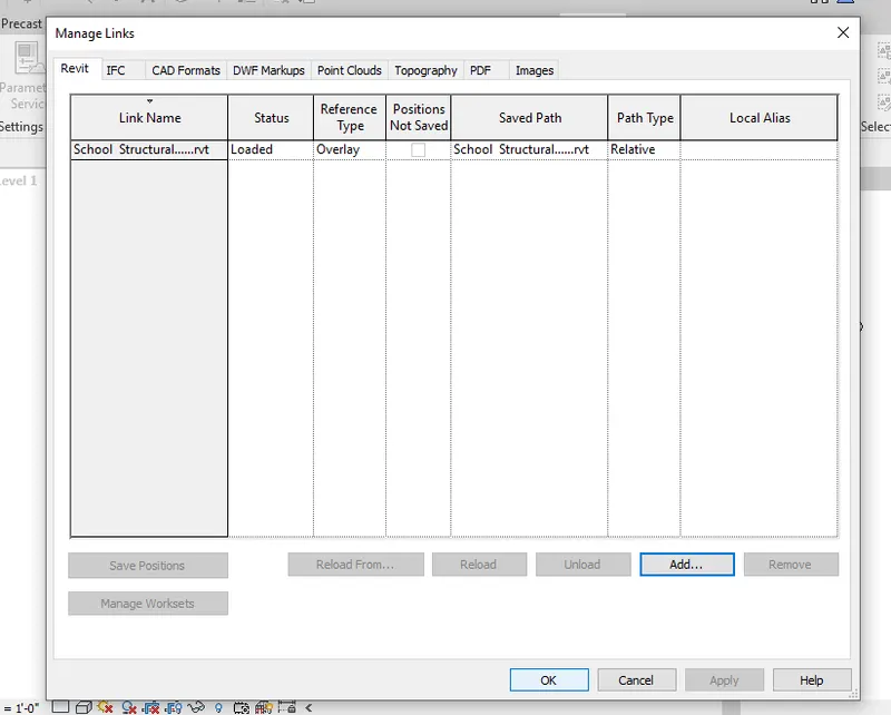
- Click on ok
Step 6:
- To provide the wall
- Go to the architecture tab
- Click > wall
- Select wall type
- Edit wall as per the requirements
- Provide the wall to the required level
Step 7:
- To provide partition
- Go to the architecture tab
- Click > wall
- Select wall type
- Edit wall as per the requirements
- Provide the wall to the required level
Step 8:
- To provide the details to buildings
- Go to the insert tab
- Click on > Load Autodesk family
- Select the family which is required
- Load the required elements to the school building
- Provide all the required elements at the appropriate positions
Step 9:
- To provide the Topography
- Go to the massing/site tab
- Click on >toposurface
- Give the elevation > 0
- Place the points on site for the elevation of the surface
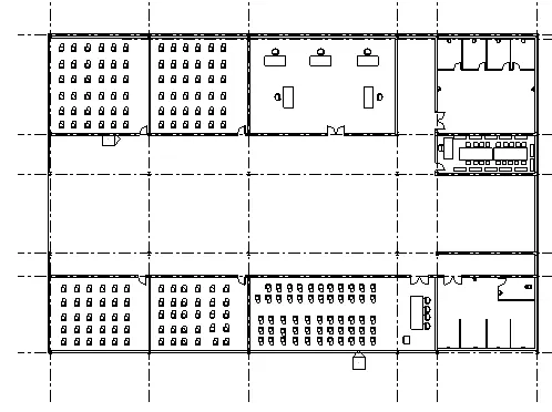
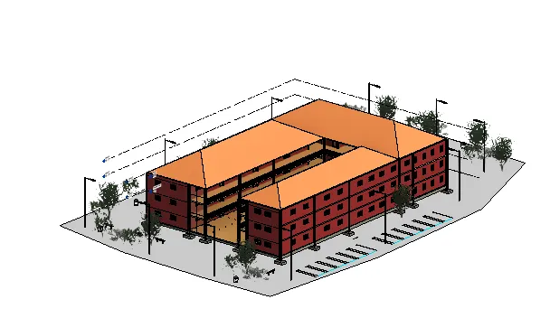
Result:
ALL the like walls,partition walls, Provide internals and externals elements, topography , Stairs, Curtain wall, Placing doors, windows in appropriate position :
5) Provide a set of drawings in an architectural and structural model to list the following details with categories and appropriate sheet templates included
a. Floor Plans with Annotations
b. Elevations
c. Sections
Procedure:-
Step 1:
- Open Revit software
- Open the file of school Architectural
Step 2:
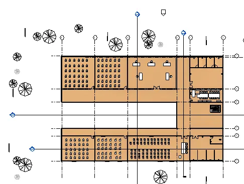
- Double click on ground floor plan
- Go to the view tab
- Click on > section
- Draw the longitudinal as well as transverse section lines
Step 3:
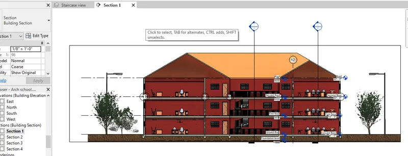
- go to the properties browser
- click > section
- Double click on > section 1
- Section 1 window will open
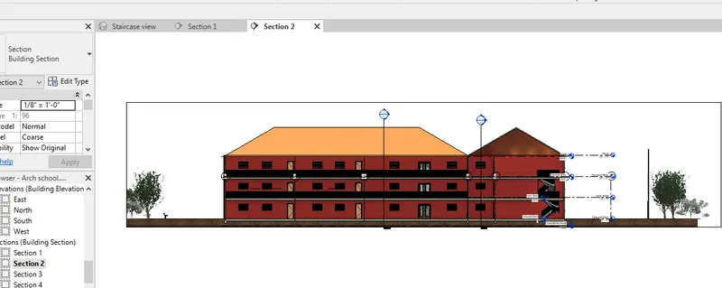
- go to the properties browser
- click > section
- Double click on > section 2
- Section 1 window will open
- go to the properties browser
- click > section
- Double click on > section 3
- Section 1 window will open
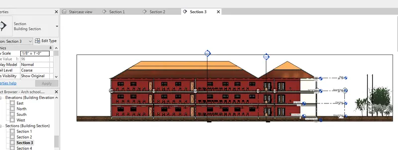
- go to the properties browser
- click > section
- Double click on > section 4
- Section 1 window will open
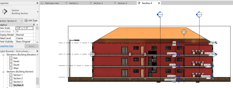
Step 4:
- Go to the view tab
- Click on sheet
- Select size of sheet
- Click > ok
- Drag the views/plans on sheet by double clicking on particulars views/plans on the sheet
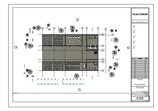
- Simmilarly create the sheet for the other plans and views
Result:-
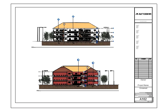
1. Floor plans
Ground floor
First floor
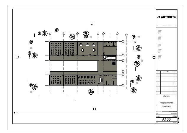
second floor
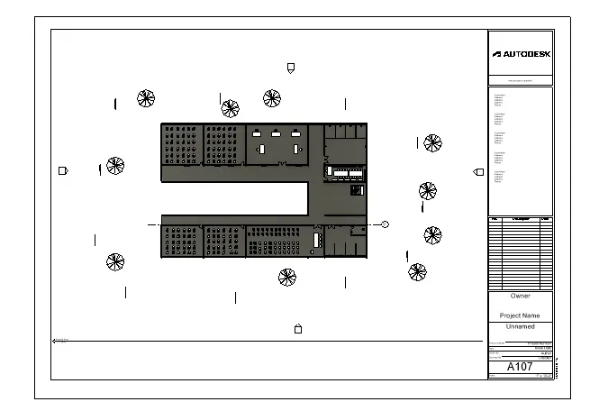
2. Sections:-
Section 1 and 2:
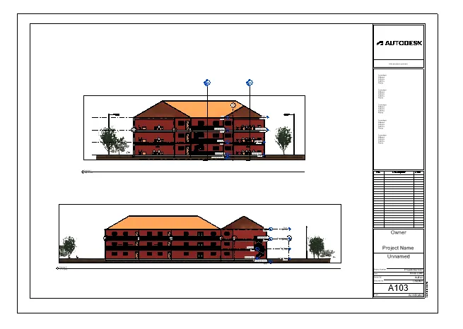
Section3 and 4:
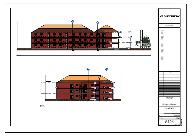
3. Elevations:-
North-South elevation:
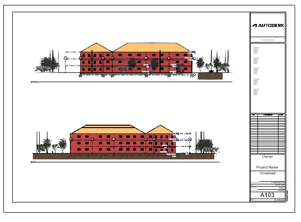
East-West elevation:
6) Using the Rendering settings, Render images of the 3D model produced and include the rendered images to the drawing sheets
a. Rendering from interior rooms
b. Rendering from out showing topographic features
c. Rendering through structural framing
Procedure:-
Step 1:
- Open Revit software
- Open the file of school Architectural
Step 2:
- Double click on ground floor plan
- Create the camera views for the different rooms
- In my project : I create the camera view for the Staff room , Library, Classroom
- See the camera view for the Library
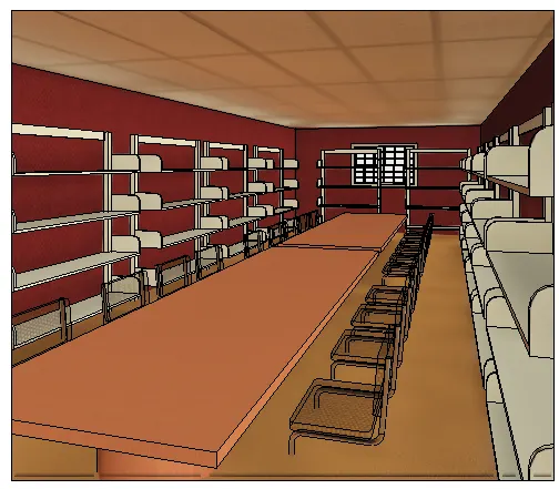
- Simillarly create the camera views for the other rooms
Step 3:
- For the render the particular view
- Open the view
- Make it realistic visuality
- Click on Render
- Set all appropriate and required setting
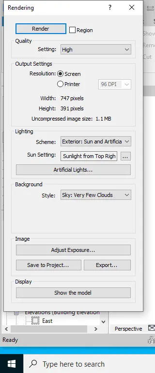
- Click on Render
- After the Rendering process completed
- Click on save the project
- Save the render views by giving the appropriate names
- Click on > ok
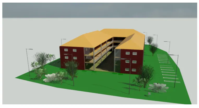
- See the render views by double clicking on particular rendered view
Step 4:
- To place the rendered view/plan on sheet
- Go to the view tab
- Click on sheet
- Select size of sheet
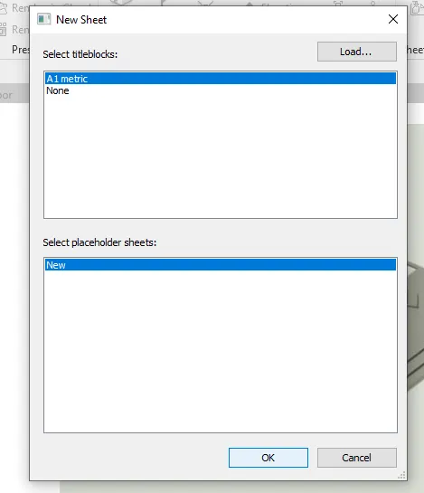
- Click > ok
- Go to rendering
- Drag the rendering views/plans on sheet by double clicking on particulars views/plans on the sheet
Result:-
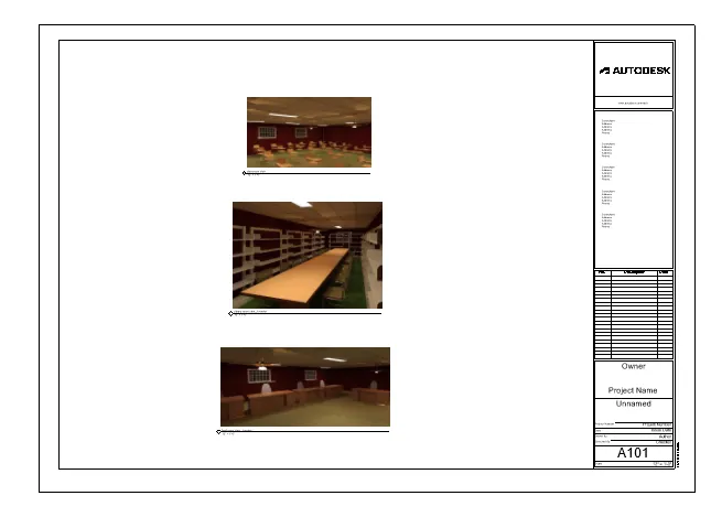
1. Rendering of internal view of room
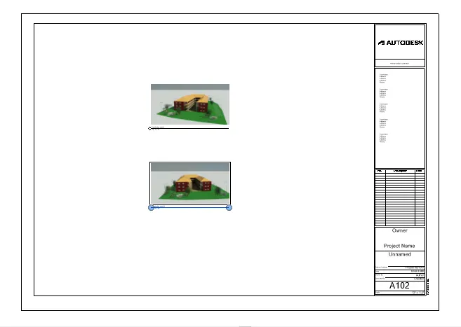
2. Rendering of External view with topographical features
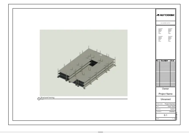
3. Rendering of Structural framing
7) Print the set of drawing sheets created and submit the drawings from the architecture and structure model
Answer:-
Done by the printer