Creating Architectural and Structural model with 3D rendering using REVIT
1) Select the type of structure you want to build from one of the three below:
a. Multi-Unit Residential Apartment
b. Office Buildings
c. School
The type of structure selected for the project from the above option is office building.
2) Assume reasonable assumptions for geographic and location details for your project modeling. Based on assumptions and type of structure selected identify the modeling requirements from NBC
As per NBC guidelines the requirements such as open space around the building should not be less than 4.5m, the FAR value should be 2.9 are the reasonable assumptions considered before designing the office building for the project.The total square feet area considered for the project is 28,000.Similarly, the height of the floor is fixed as 12' which also follows the NBC guidlines for height limitations.
3) Using the structural model, include the following components based on the type of structure selected
a. Foundation – Isolated / Wall/Matt Foundation
b. Columns
c. Beams Connected to Columns
d. Roof Framing/ Truss
e. Floor / Decks
f. Floor Openings for Elevators and Stairs
Aim: To provide founation,columns,beams and other structural components in the structural model of the project.
Introduction: In any project model creation after the architectural model creation, creating a structural model is the foremost important thing by providing structural components such as beam,columns and floors whihc forms the basic frame work of the structure. The structural model is mainly created for the analysis of the structure for checking stability.The size of all the elements are given approximately and subject for change as per the analysis.
Steps:
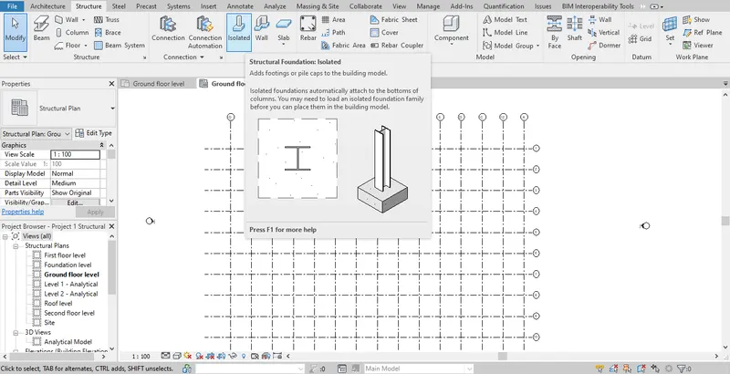
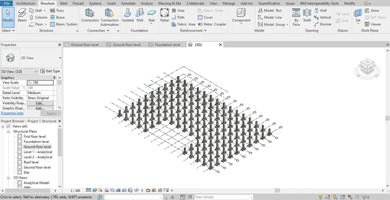
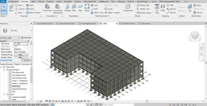
- After the grid creation the 1st step in the struictural model is creation of foundation
- In the stucture tab different types of foundation such as isolated,wall are given and isolated footing is chosen for this project and selected from the ribbon
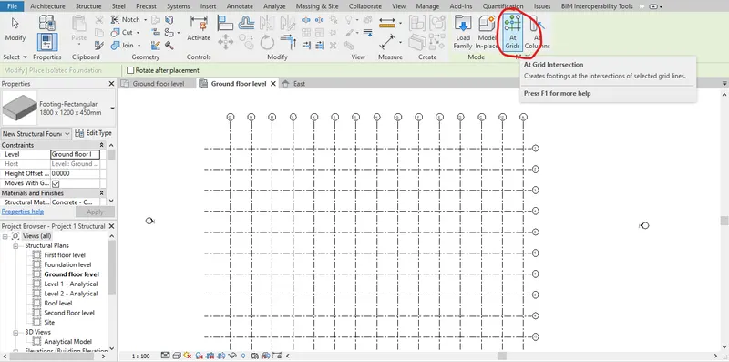
- Then on grids option is selected from the ribbon and the foundations are placed at foundation level of the structure which is 4' below the ground level
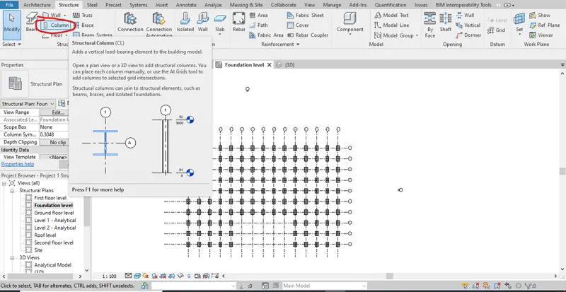
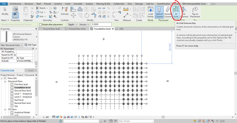
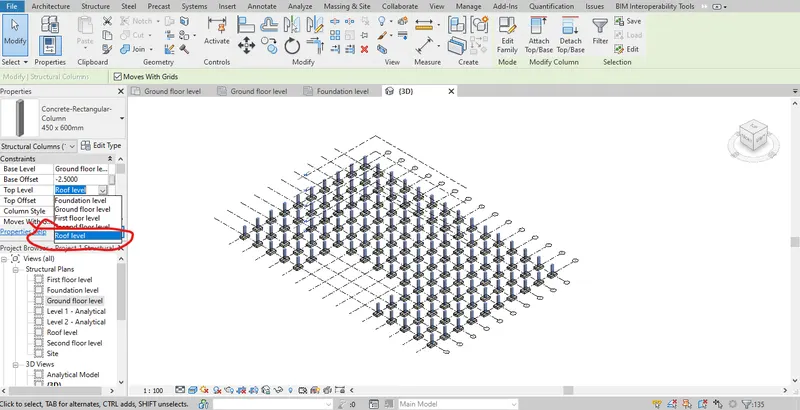
- Then for columns, column option is selected from the ribbon in the structure tab followed by on grids option in the ribbon and the columns are placed at the grids
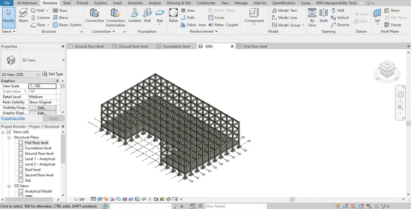
- The foundation and columns are provided at all grid intersections and are removed as per the plan of the structure.
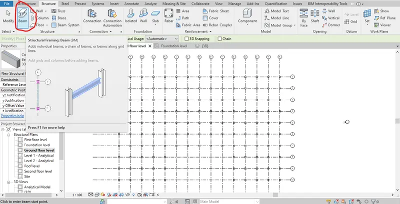
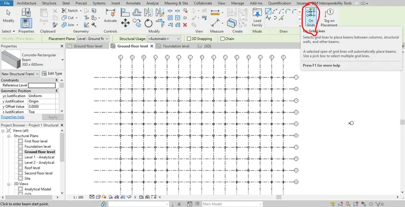
- For providing beams again from the structure tab in the ribbon beam option is selected, followed by on grids option
- Then the beams are edited as per the plan
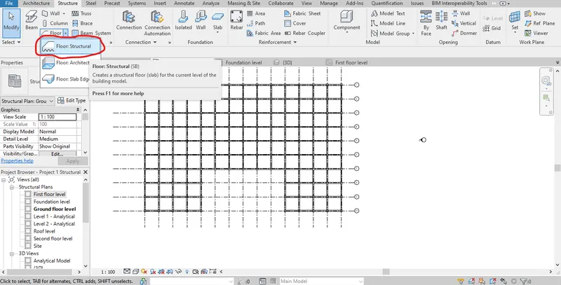
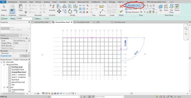
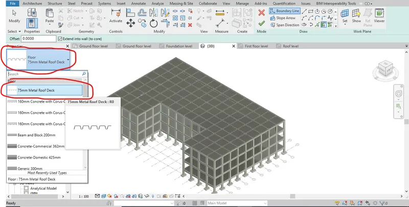
- Then using the floor option in the structure tab of the ribbon floors are provided by line tool and it is placed at an elevation where it rests on beams.
- Then all the beams,columns are selected and copied using the copy option
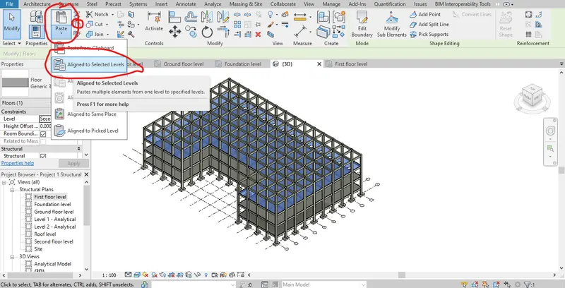
- Then in the paste option assign to select levels option is selected and pasted to the other levels such as 1st,2nd and roof level. Similarly the floors are copied and pasted in 1st and 2nd floor.
- Then using the floor option from the architecture tab roof is provided in the roof level of the structure
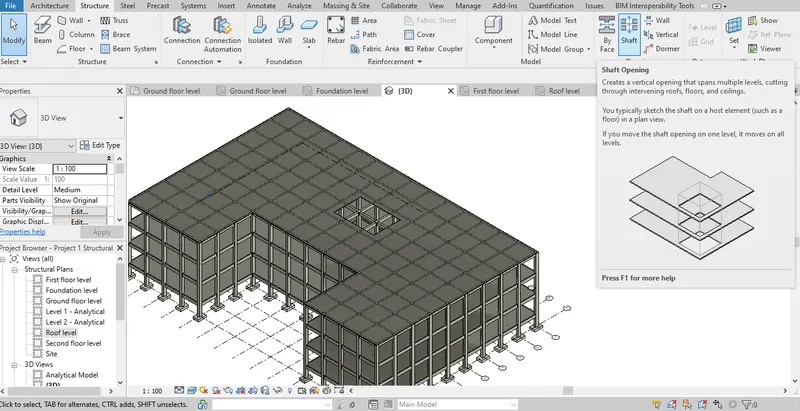
- Finally for providing openings for lifts and staircase area in the floors shaft option is used from the structural tab of the ribbon
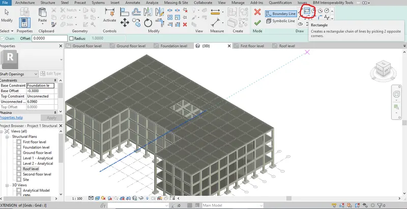
- After selecting shaft option using the rectangular draw tool it is drawn. In this case the shaft opening is provided with a size of 20'x20'
Results: Thus the stuctural components and shaft openings are provided sucessfully to the model.
4) Using the architectural model, include the following components based on the type of structure selected
a. Wall Layout with appropriate material and finishing
b. Exterior façade with fancy finish
c. Interior partition walls to size rooms
d. Components to add details to a room ( Desk, Chair, Lighting, Plumbing fixtures)
e. Add components such as stairs Elevators
f. Have at-least one side of the building with curtain walls and glass panels
g. Include interior and exterior lighting fixtures
h. Place proper topographic components from outside ( Trees, Parking, Plants) to add details to the model
Aim: To provide architectural components such as walls,aesthetic components and topographic features to the project model.
Introduction: In the process of model creation the vital part is to provide more details of the building as much as possible to make sure that the common people who view the model to get a clear picture of the building as seen in real. In that process every components such as lights,chairs,tables, etc., are provided to get a better understanding of the functionality of the rooms suggested.
Steps:
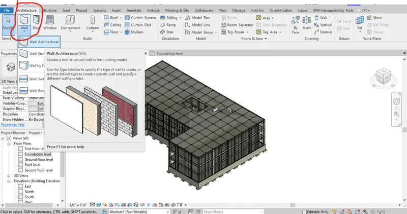
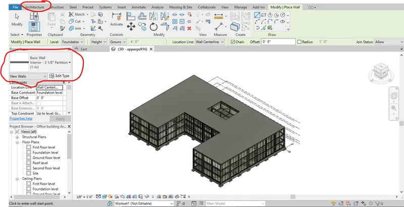
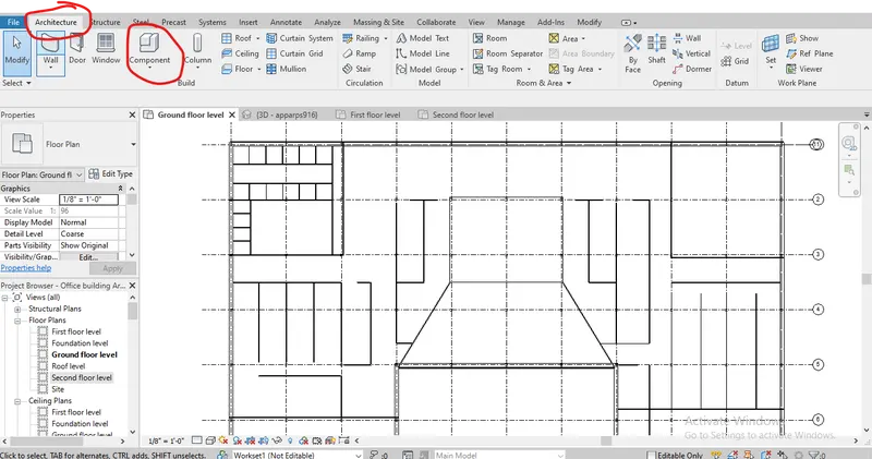
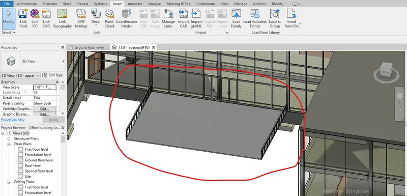
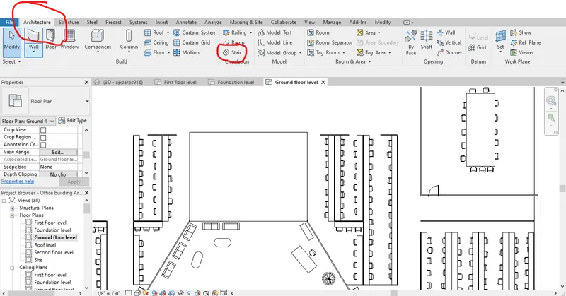


- Walls are provided by selecting wall option in the arechitectural tab of the ribbon
- Using the line tool the external walls are drawn and finished. The external wall used in this building is external glazing and store front to provide a aesthetic view.
- Then again using wall option interior walls are provide to divide the area into rooms.In this two types of interior walls are provided one for providing rooms and one for providing workspace area.
- Furthermore required componets such as chair,desks and tables are provided.
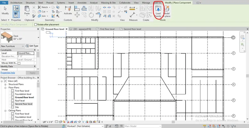
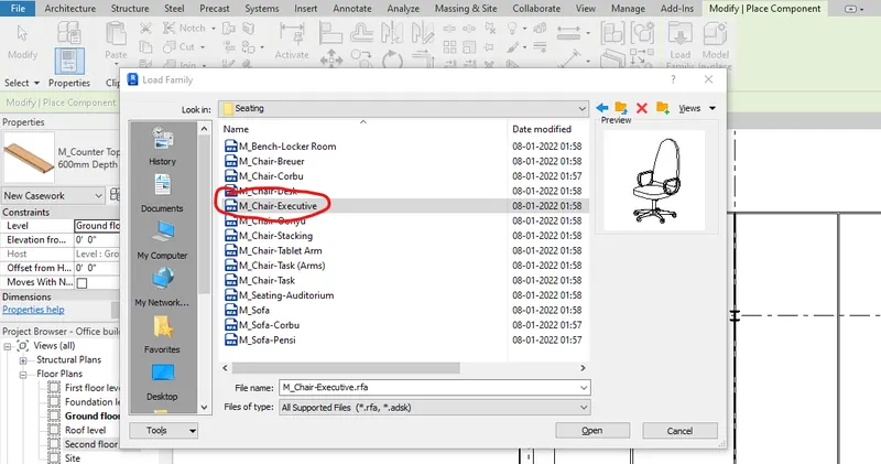
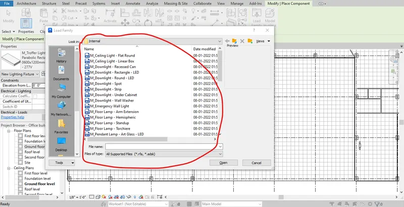
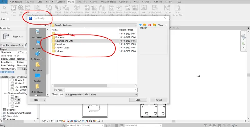
- For placing any component in the model one general step is used Architecure tab>Component>Place a component>Load Family
- The above step is common for placing any component in the model
- In this project some of the table components are created and placed in the project
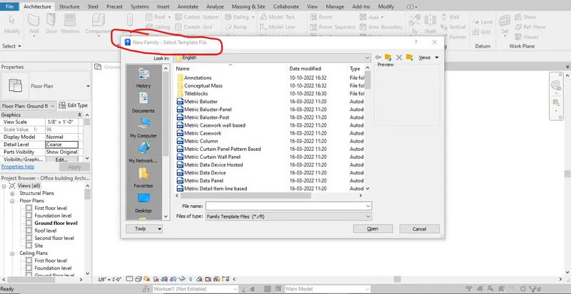
- For creating any componets such as tables of customized sizes New family option is selected
- After selecting the option the type of the family should be selected such as furniture for table
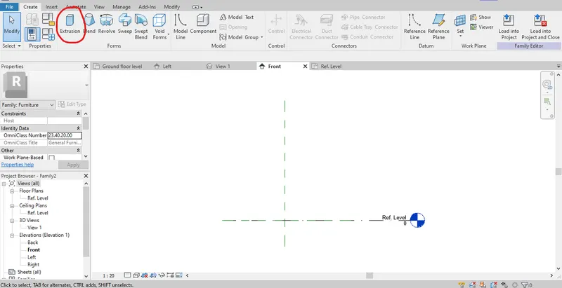
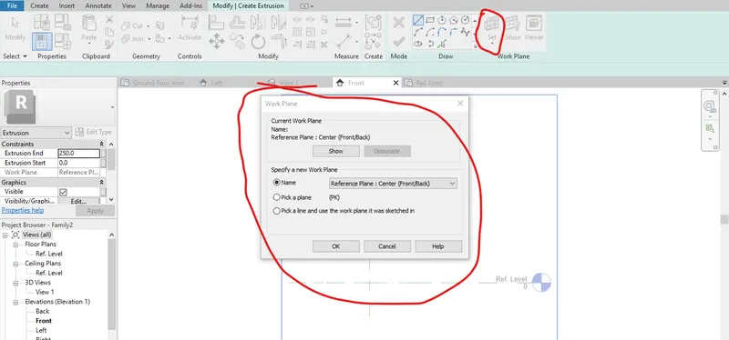
- Then same project like revit screen opens and in that work plane is fixed 1st using the set>plane option from the ribbon
- After selecting the plane using the extrusion command from create tab of the ribbon and using the draw tools such as rectangle or line component is created of required size.
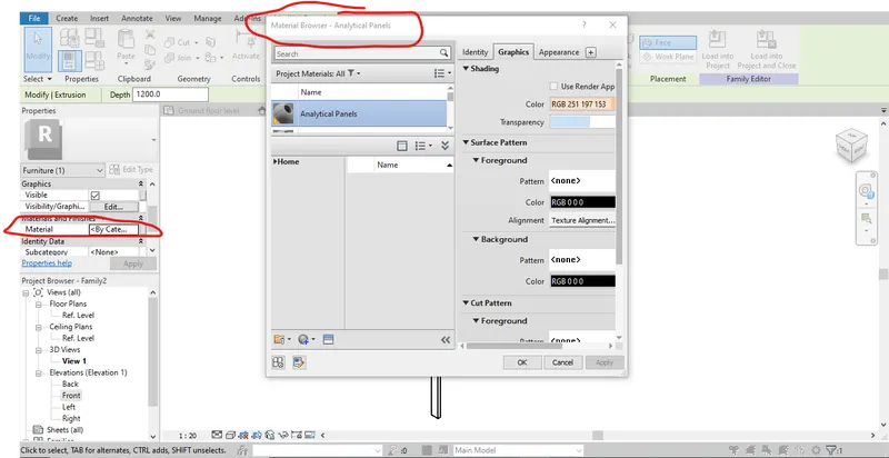
- Then materials are assigned from the properties browser in the left.
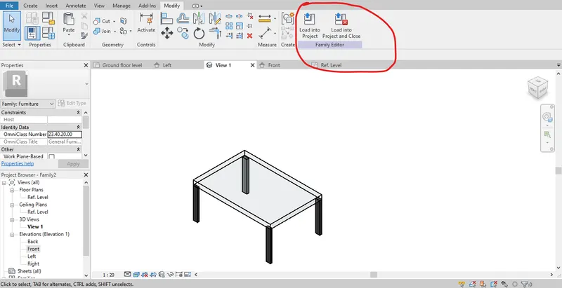
- Finally after finishing load into project and close command is selected from the ribbon and the created component can be loaded into project and can also be saved in the families for future use.
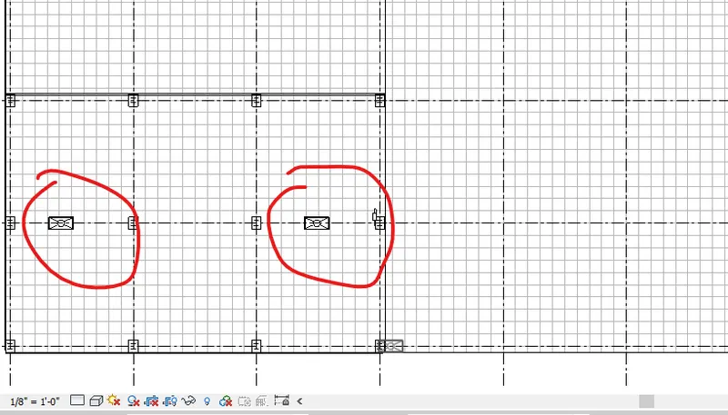
- All the components are loaded and placed in the model wherever required and as per the functionality of the room.
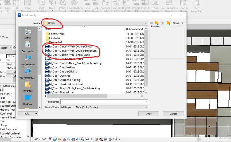
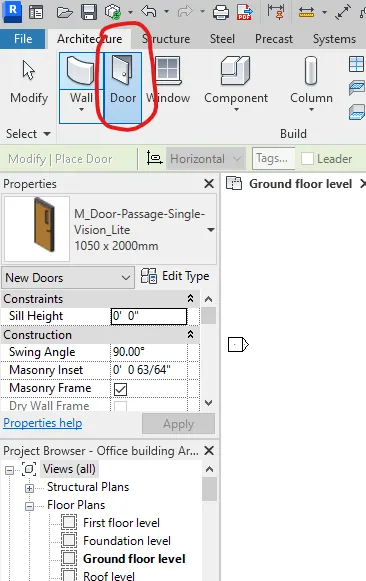
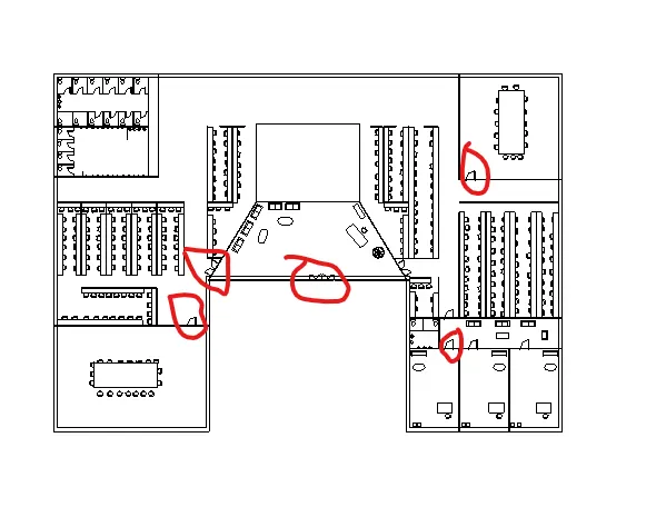
- Then for placing doors Architecture tab>Doors>Load family command is used. Using the command different types of doors can be loaded from the family and are placed in the model.
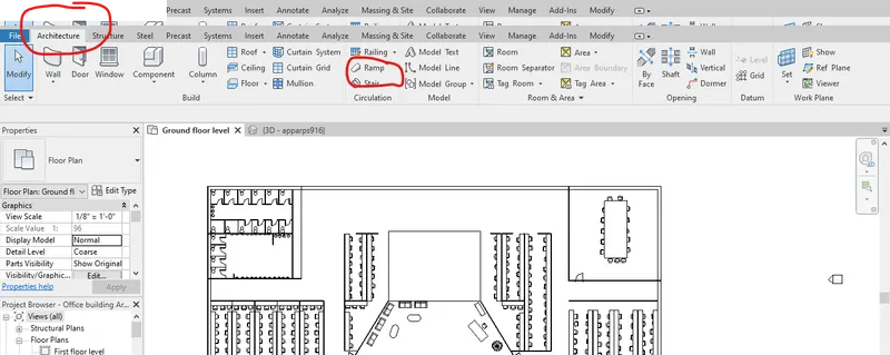
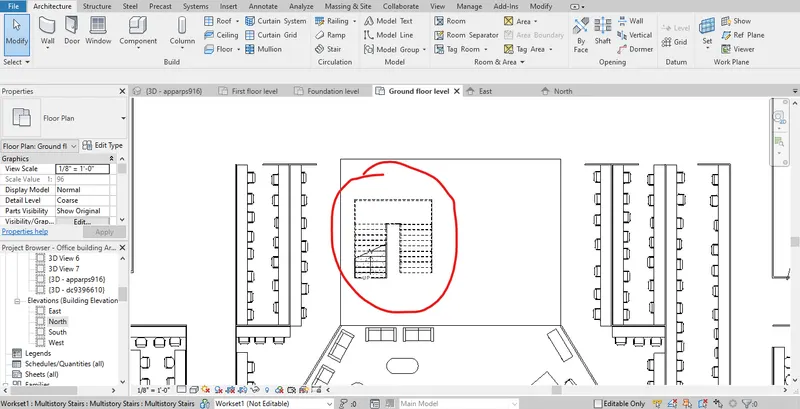
- For providing stairs Architecture tab>Stairs command is used from the ribbon. The width of stairs can be edited in the properties browser.
- For providing elevators in the model Architecure tab>Component>Place a component>Load Family is used and the elevators are availabe as speciality equipment folder
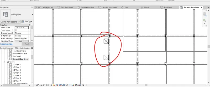
- Since lighting is also a component same Architecure tab>Component>Place a component>Load Family command is used and different type of lights are provided based on their usage and functionality of the rooms.The lightings are provided in the ceiling plans of the each level.
- For providing ceilings, ceiling option is selected from the architectural tab of the ribbon and are drawn using the line tool.
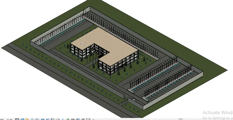
- Finally for modelling the external area of the building massing and site tab is used.
- In massing and site tab toposurface option is used for providing the surface of area for building and it is given using the points
- Then using the building pod option toposurface is seperated from the building by selecting the edges of the building.
- Then using the split surface option roads can be provided in the project by drawing lines using line tool
- The materials are assigned to the surface from the properties browser
- The parking components are provided by selcting parking component option in the massing and site tab and loading it to the model.
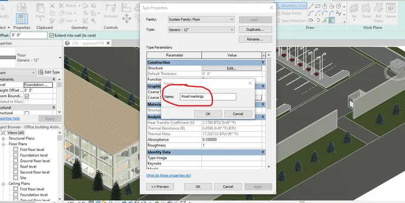
- Then road marking are proivded using the floor option by drawing a small marking like structure floor and placing it at a definite distance by using the array command in the ribbon
- Street lights and tree like structures are provided using the same place a component option.
Results:Thus all the architectural components are placed and topographical structure is drawn sucessfully.
5) Provide a set of drawings in an architectural and structural model to list the following details with categories and appropriate sheet templates included
a. Floor Plans with Annotations
b. Elevations
c. Sections
Aim: To provide a list of drawing such as floor plans ,elevations and sections of the building model created.
Introduction: After creation of a building model the next step is to provide mandatory drawings to the field and higher authority for approval. The list of mandatory drawings to be provided are Floor Plans with Annotations, Elevations,Sections of the building model created.
Steps:

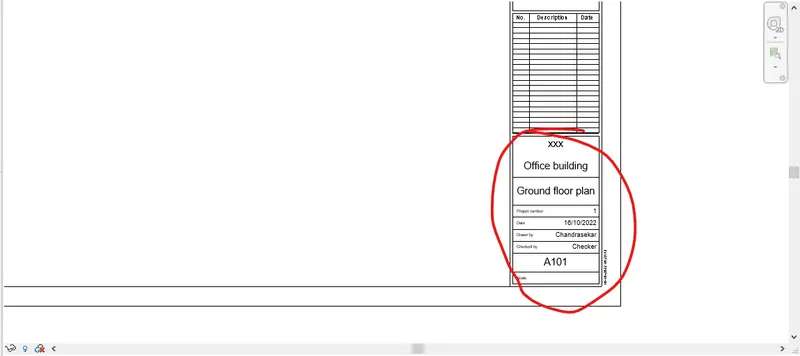
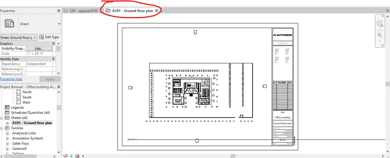
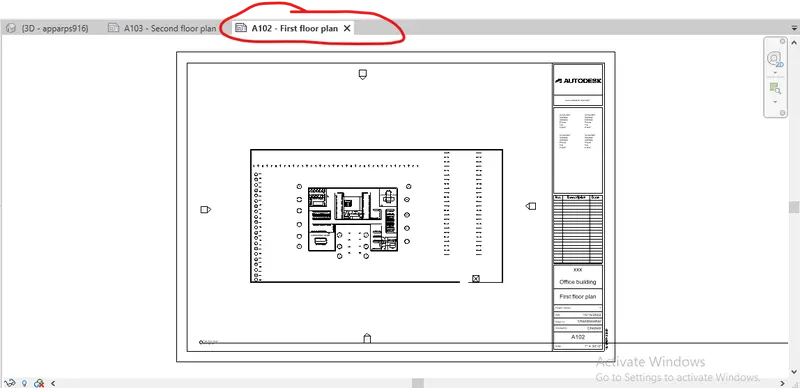
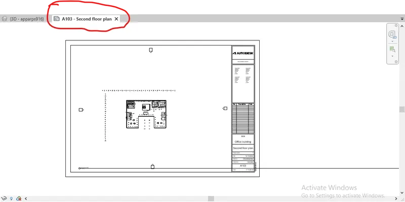
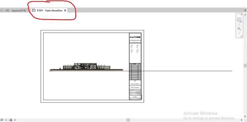
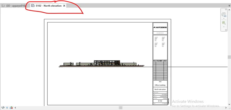
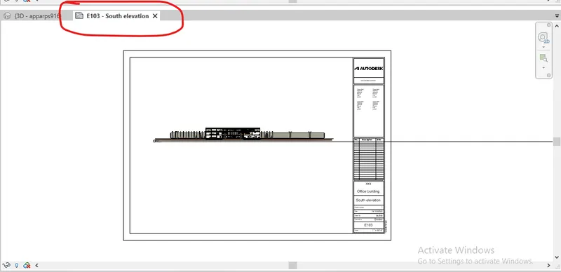
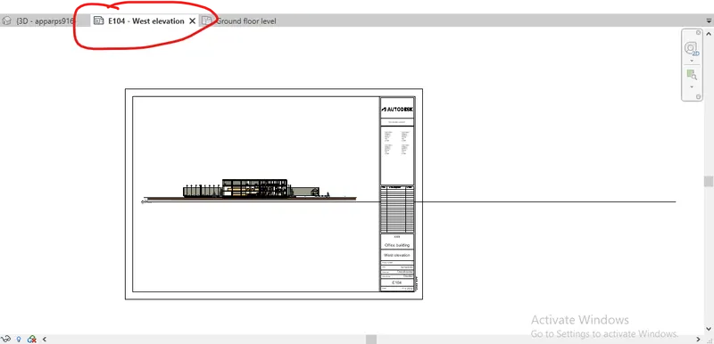

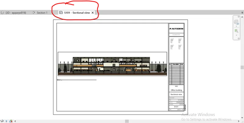
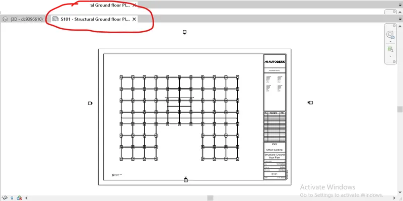
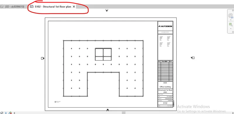
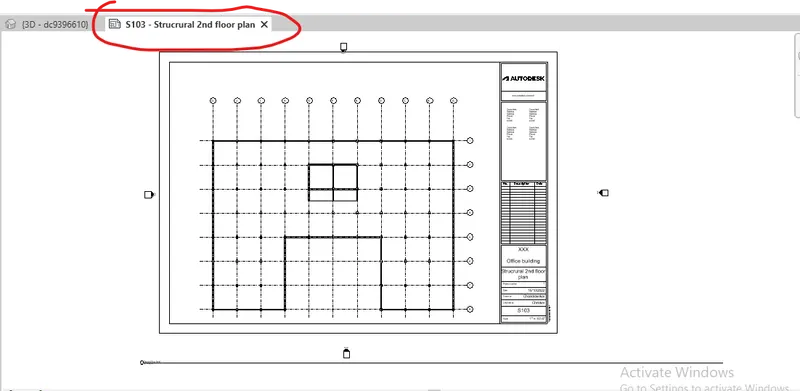
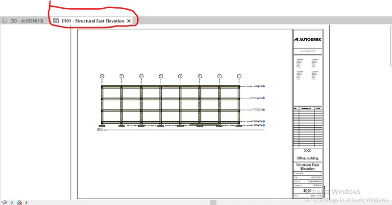
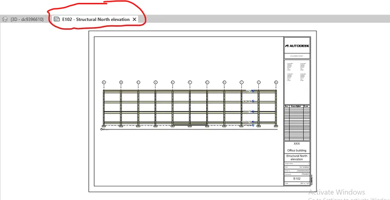
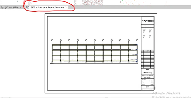
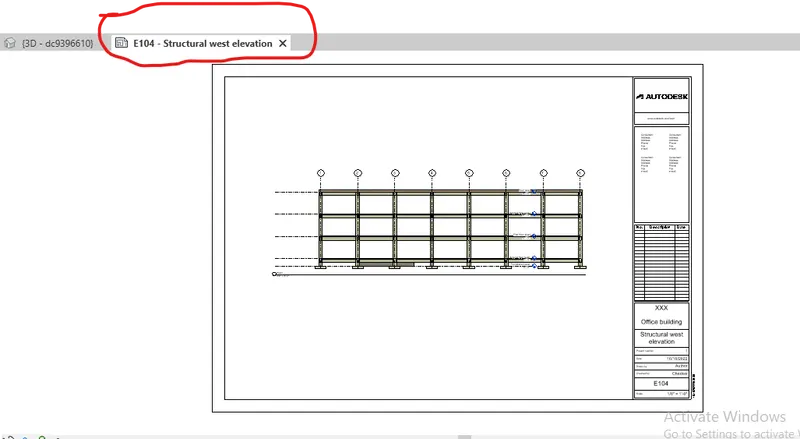
- For presenting the different types of drawing sheets are used which contains information about the project and a specific sheet number for the specific drawing is provided to avoid confusion
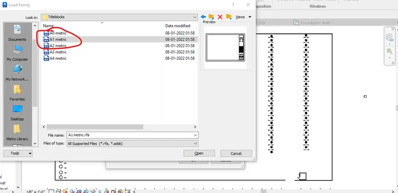
- For creating sheet view>Sheet command is used and A1 size sheet is used for this project which is loaded from the titleblocks family
- Then after loading the sheet requied views are dragged from the project browser and placed inside the sheet
- To adjust the scale for placing the views correctly fitting into the sheet propesties browser is used
- The information can be edited either in the sheet itself or in project information command in manage tab.
Results: Thus the required views are provided in the sheet sucessfully.
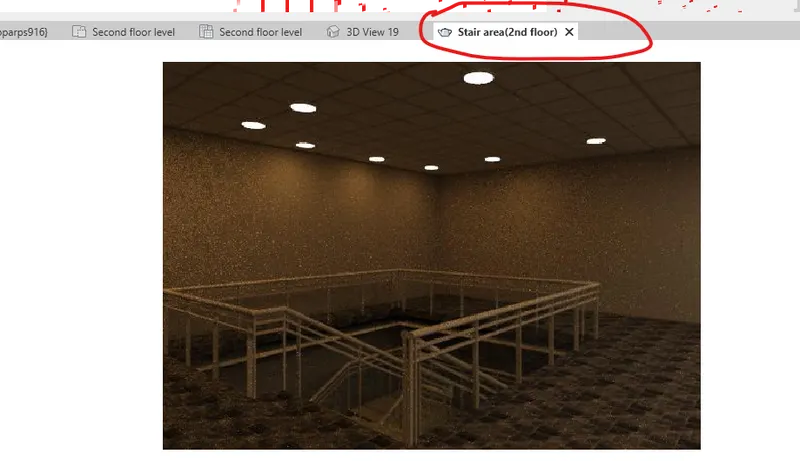
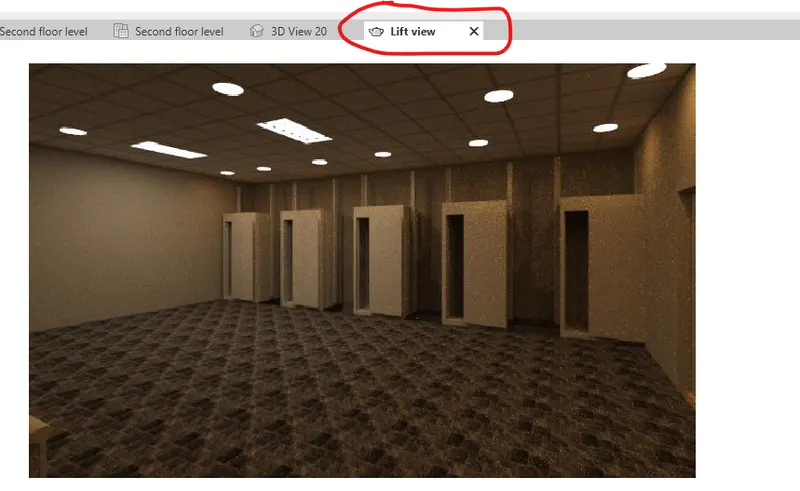
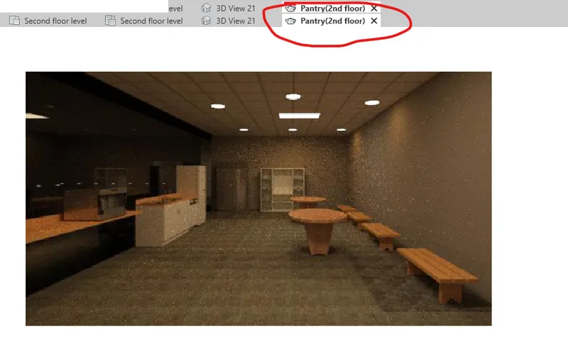
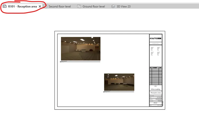
6) Using the Rendering settings, Render images of the 3D model produced and include the rendered images to the drawing sheets
a. Rendering from interior rooms
b. Rendering from out showing topographic features
c. Rendering through structural framing
Aim: To provide renderings of the required views of the 3D model of the project.
Introduction: After finishing the project rendering process is done to provide realistic view images of structure. This provides the clear idea of a particular place in the model or the whole model can also be rendered.
Steps:
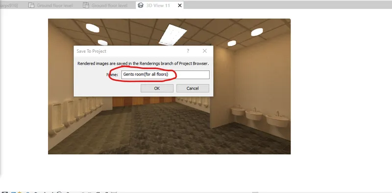
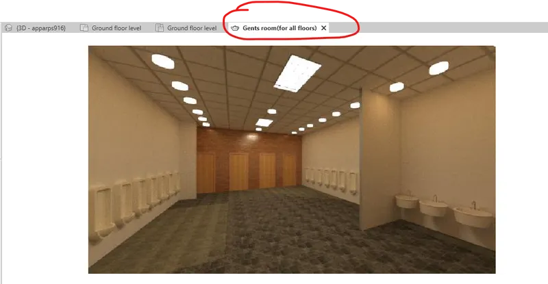
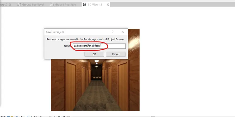
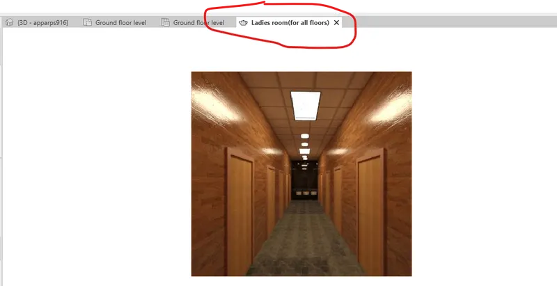
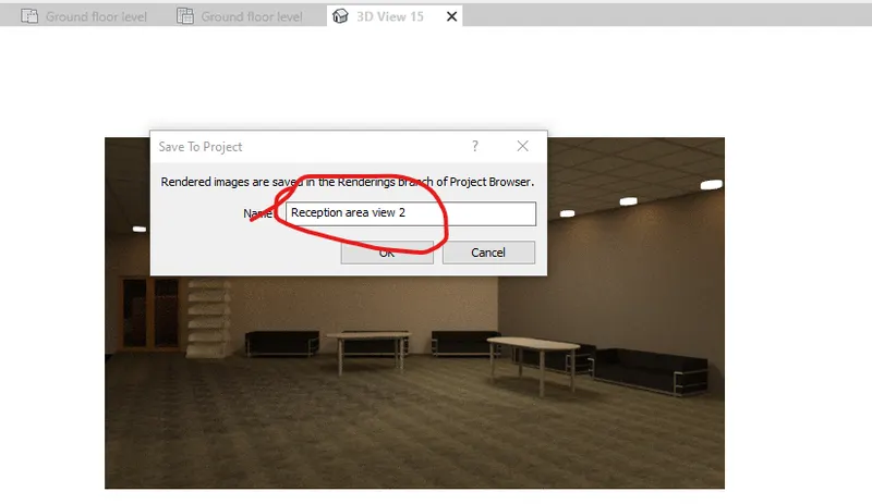
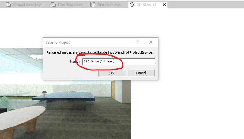
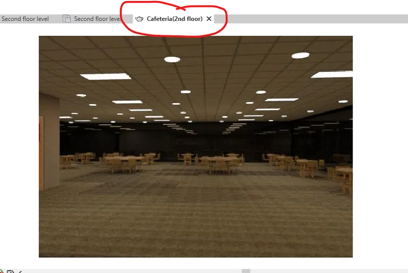
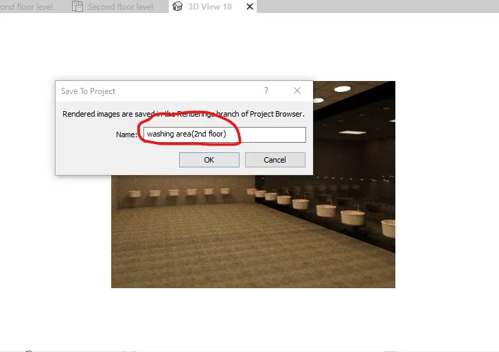
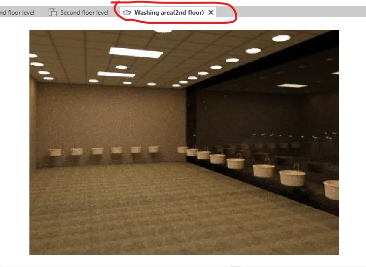
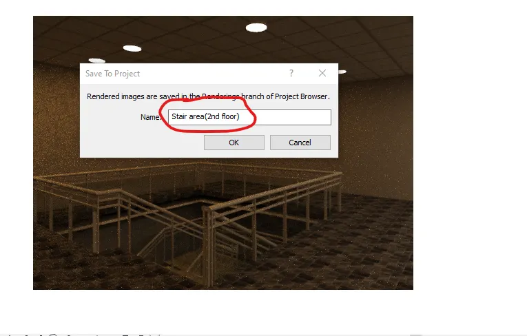
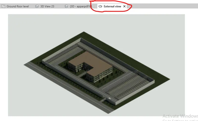
- For creating default 3d view or specific 3d views of the project view tab is used
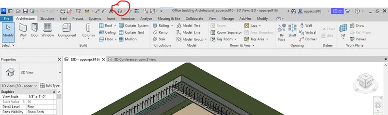
- In the view tab by clicking 3d command, camera option is selected
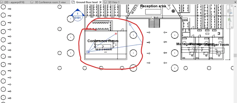
- After selecting the camera option a camera like component appears and it is placed wherever required in the mode
- The view range of the camera can be edited manually
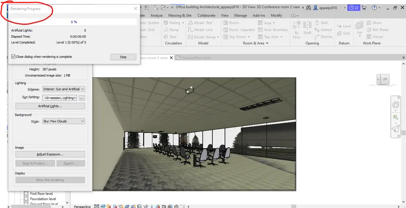
- After placing the camera and the range by using the shortcut key 'RR' rendering is done
- When 'RR' is selected a dialog box appears in which rendering settings such as quality,lighting can be fixed and upon selecting render the view is rendered
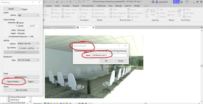
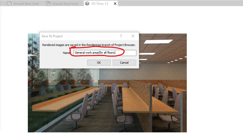
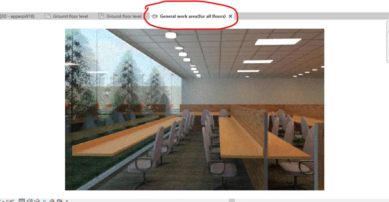
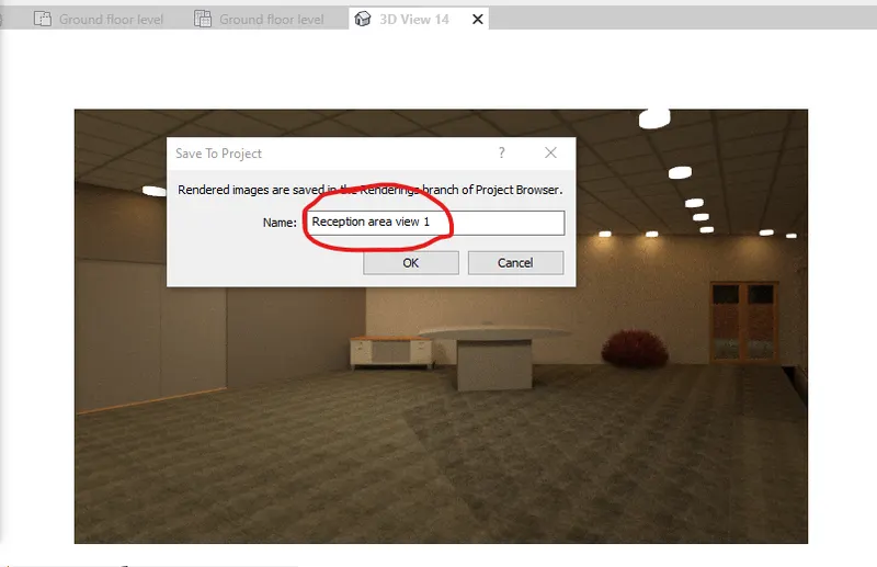
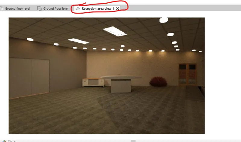
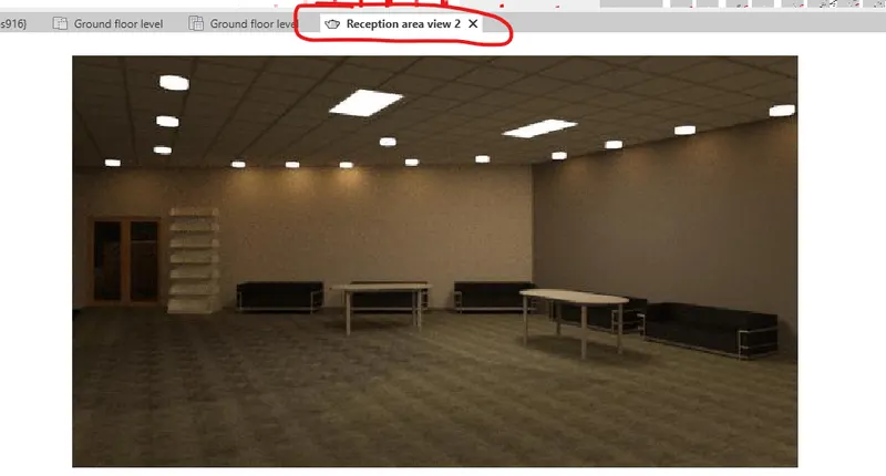
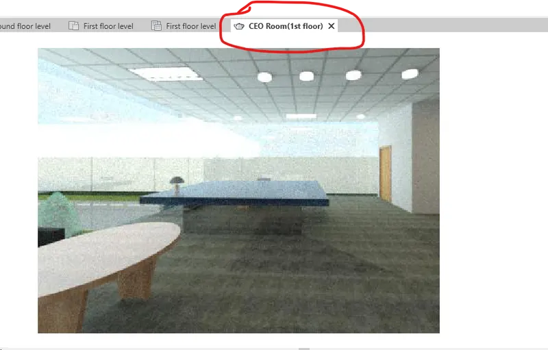
- Then using save to project command in the dailog the rendered image can be saved with the required name
- The images can be added to the sheet by view>sheet command and dragging the rendered images from the project browser and the information can be edited in the sheet.
Results: Thus the specfic 3d views are rendered sucessfully.
7) Print the set of drawing sheets created and submit the drawings from the architecture and structure model
Aim: To Print the set of drawing sheets created and submit the drawings
Introduction: The final step of any project creation is to provide the created sheets of model in physical form by printing as per the paper size.
Steps:
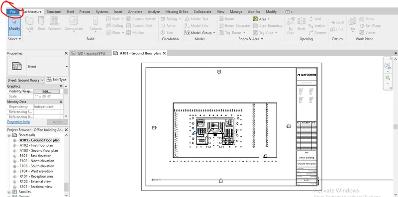
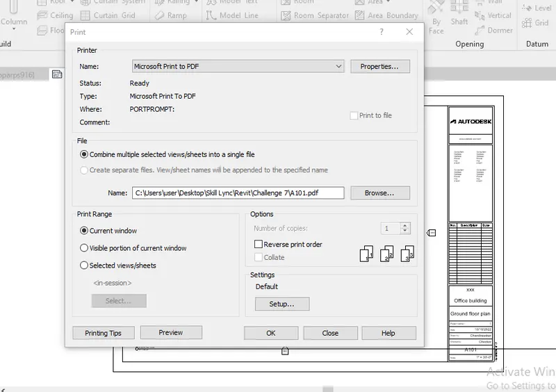
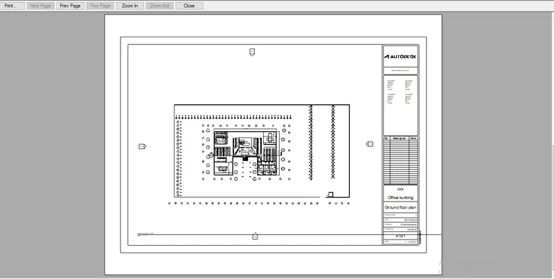
- Two options are available for printing any sheet One is simply using the shortcut key ctrl+p
- Other one is by selecting file command at the top left corner and print option
Results: Thus the sheets are converted into pdf sucessfully.