Creating Architectural and Structural model with 3D rendering using REVIT
1.0
Ans: In this project I am going to build an office building
It comes under Group E : Business Buildings according to NBC
This type of buildings are constructed for carrying out business related activities. The main purpose of such buildings is to carry out business transactions, keeping of important records and accounts etc. It includes city halls, dispensaries, clinics, libraries, office buildings etc.
2.0
The plinth or any part of a building or outhouse shall be so located with respect to average road level from site so that adequate drainage of the site is assured but at a not height less than 45 cm
The maximum height of building shall not exceed 1.5 times the width of road abutting plus the front open spaces.
If a building abuts on two or more streets of different width, the building shall be deemed to face upon the street that has the greater width and the height of the building shall be regulated by the width of that street. Height shall however, not exceed the maximum height as provided in the Master Plan.
a)Every building meant for human occupancy shall be provided with exits sufficient to permit safe escape of occupants in case of fire or other emergency.
b) In every building exit shall comply with the minimum requirement of this part, except those not accessible for general public use.
c) All exists shall be free of obstructions.
d) No buildings shall be altered so as to reduce the number, width or portion of exits to less than required.
e) Exits shall be clearly visible and the routes to reach exits shall be clearly marked and signs posted to guide the occupants of floor concerned.
f) All exit ways shall be properly illuminated.
g) Fire fighting equipment where provided along exits shall be suitably located and clearly marked but must not obstruct the exit way and there should be clear indication about its location from either side of the exit way.
h) Alarm devices shall be installed to ensure prompt evacuation of the occupants concerned through the exits, wherever required.
i) All exits shall provide continuous means of egress to the exterior of a building or to an exterior open space leading to a street.
j) Exits shall be so arranged that they may be reached without passing through another occupied unit, except in the case of residential building
The minimum area for office room/shop or any other space to be used as workspace shall not
be less than 6.0 sq m. with a minimum width of 2.1 m.
My project is in plain area
Area is commercial.
Road width infront of the office building is 70 ft.
3.0
AIM: To includes structural components to the structural model.
INTRODUCITON:
In this project, the procedure of desning of building is done from start to end.
Generally architectural engineer work on project 1st and then structural and then MEP dicipline engineer work on project.
Information regarding how model architectural elements, structural elements and how to use collabration is done very spefic in this project.
PROCEDURE:
1) Open REVIT and make horizontal and vertical grids according to plan of building.
2) Grids are annotation elements that help organize your design.
- On the ribbon, click Grid
- Architecture tab>Datum panel>Grid
- Structure tab>Datum panel>Grid
- Click Modify | Place Grid tabDraw panel and select sketch option.
Use Pick Lines to snap the grid to an existing line, such as a wall.
- Click when the grid is the correct length.
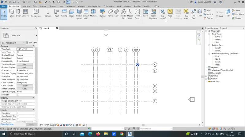
3) Increase the number of levels upto roof and rename them as ground level, founadtion , first floor, second floor, and roof.
4) In addition to creating a level for each story in a building, you can also create reference levels, such as sill level.
- Open the section or elevation view to add levels to.
- On the ribbon, click >Level
- Architecture tab>Datum panel>Level
- Structure tab>Datum panel > Level
- Place the cursor in the drawing area and click.
5) As we place the cursor to create a level, if the cursor aligns to an existing level line, a temporary vertical dimension displays between the cursor and that level line.
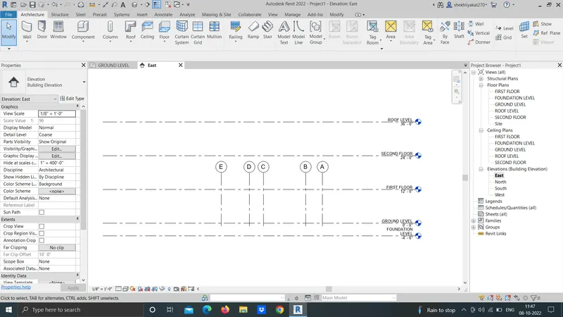
6) Select column from ribbon and place the columns at intersection of grids as shown.
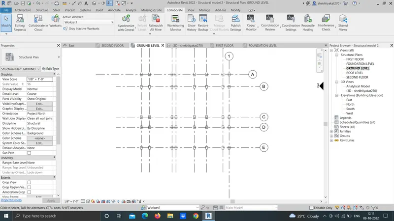
7) To publish from Revit, the model view should be the Default 3D View or a 2D Floor Plan. Use the House icon in the Quick Access Toolbar to quickly switch to the Default 3D View.Change the view to default 3d view to get an interface as shown below.
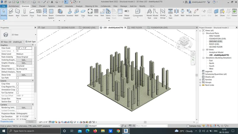
8) Place another column on the grid intersection from ground floor to first floor
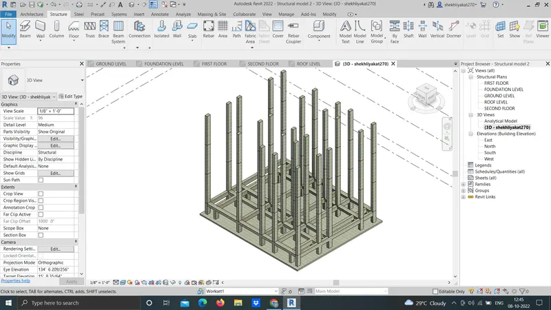
9) Select beam from the ribbon and connect this beam to different columns as shown.
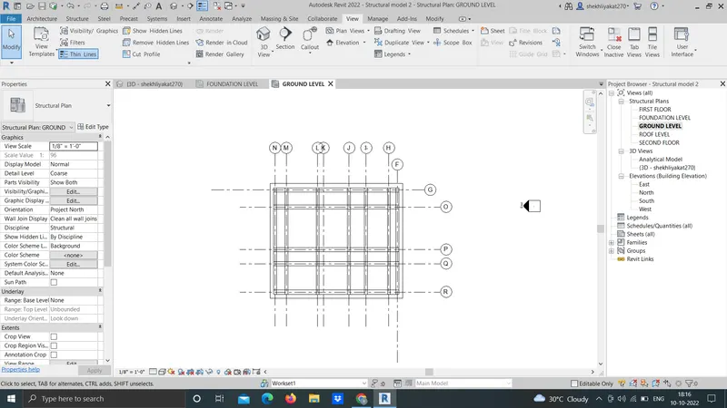
Change the view to 3d
11) Select entire figure and go to the copy option and assign them to the first floor , second floor and third floor.
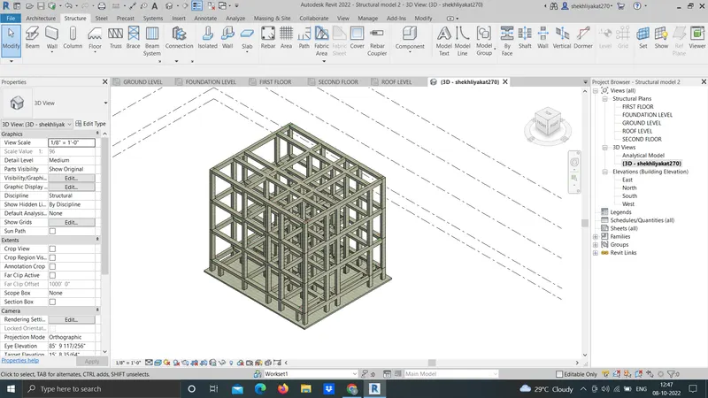
12) Select the ground floor and copy it to the assigned levels ie first floor , second floor and third floor
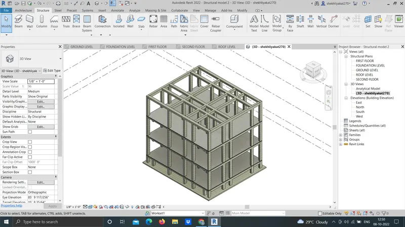
Go to the stairs option and choose any stair design , here we choose straight . Now select the base level as ground floor and upper constraint as first floor place the stair anywhere as per needed. Copy it to assigned levels ie first floor , second floor and third floor and roof . Now in the drawing plan create a shaft from ground floor to roof level where the lobbies serve as landing for the stairs
RESULT:
I understood how use revit software to draft structural model.
4.0
AIM: To create architectural model of bussiness building in revit.
INTRODUCITON:
In this project, the procedure of desning of building is done from start to end.
Generally architectural engineer work on project 1st and then structural and then MEP dicipline engineer work on project.
Information regarding how model architectural elements, structural elements and how to use collabration is done very spefic in this project.
PROCEDURE:
1) Use a Wall tool to create a non-bearing wall or a structural wall in the building model.
Non-bearing walls:
Click Wall>Architectural on the
- Architecture tab>Build panel>Wall drop-down
- Structure tab>Structure panel>Wall drop-down
Structural walls:
Click Wall: Structural on the
- Architect tab>Build panel>Wall drop-down
- Structure tab>Structure panel>Wall drop-dow
2) With the same grids drawn in the previous plan draw a wall along the boundary
3) Draw the interior partition with appropriate material and finishing and place the required furniture and components like Desk, Chair, Lighting, Plumbing fixtures ,stairs , interior and exterior lighting fixtures in the plan and change the view to 3d.
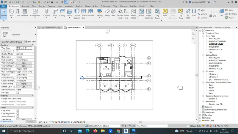
4) Change the front walls to the curtain walls- external galzed wallGo to the stairs option and choose any stair design , here we choose U shaped. Now select the base level as ground floor and upper constraint as first floor place the stair anywhere as per needed. Copy it to assigned levels ie first floor , second floor. Now in the drawing plan create a shaft from ground floor to roof level where the lobbies serve as landing for the stairs.
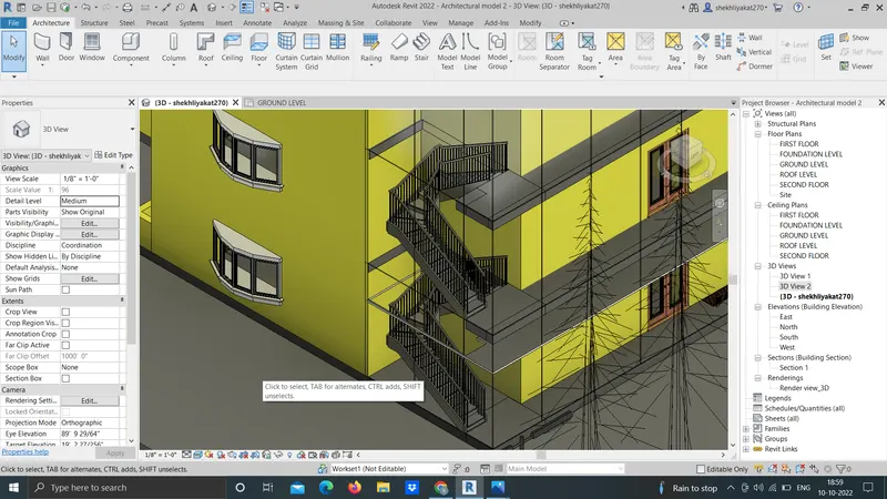
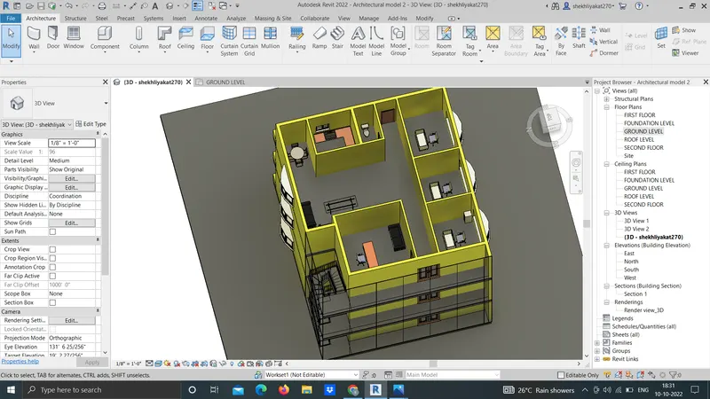
5) Copy the entire thing to all the levels ie first floor , second floor and third floor.
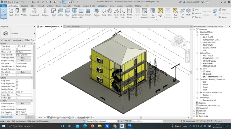
6) Roof option creates a roof using the building footprint to define its boundaries.
- Display a floor plan view or a reflected ceiling plan view.
- Click Architecture tab>Build panel>Roof drop-down>Roof by Footprint
If we try to add a roof on the lowest level, a dialog prompts you to move it to a higher level. If we choose not to move the roof to a different level, Revit notifies you later if the roof is too low.
- On the Draw panel, select a sketch or pick tool. To edit roof properties before sketching, use the Properties palette.
- Sketch, or pick, a closed loop for the roof.
- Specify slope defining lines. To change the slope definition of a line, select the line and, on the Properties palette, click Defines Roof Slope. We can then change the slope value.
- Click Finish Edit Mode, and then open a 3D view
RESULT:
I understood how to model all the architectural elements of building.
5.0
AIM: To make set of drawing from architectural and structural model.
INTRODUCITON:
In this project, the procedure of desning of building is done from start to end.
Generally architectural engineer work on project 1st and then structural and then MEP dicipline engineer work on project.
Information regarding how model architectural elements, structural elements and how to use collabration is done very spefic in this project.
PROCEDURE:
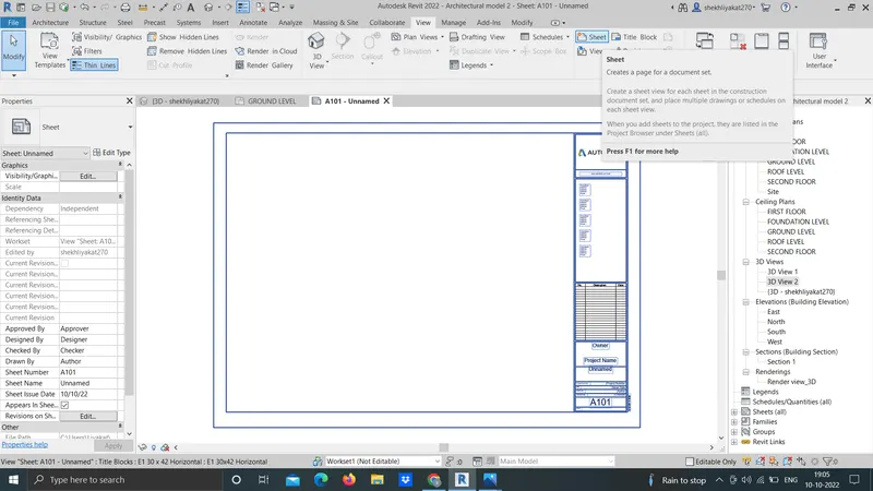
1) Create a Sheet
- Click View tab>Sheet Composition panel>Sheet
- In the New Sheet dialog, under Select titleblocks, select A1 Metric, and click OK.
- Click the title block to select the sheet, then click the sheet number, enter A1, and press Enter.
2) Add Views to the Sheet
In the Project Browser, under 3D Views, click the View to Building view title and drag it to the upper right corner of the sheet, and release the mouse button. An outline of the view displays for easier placement.
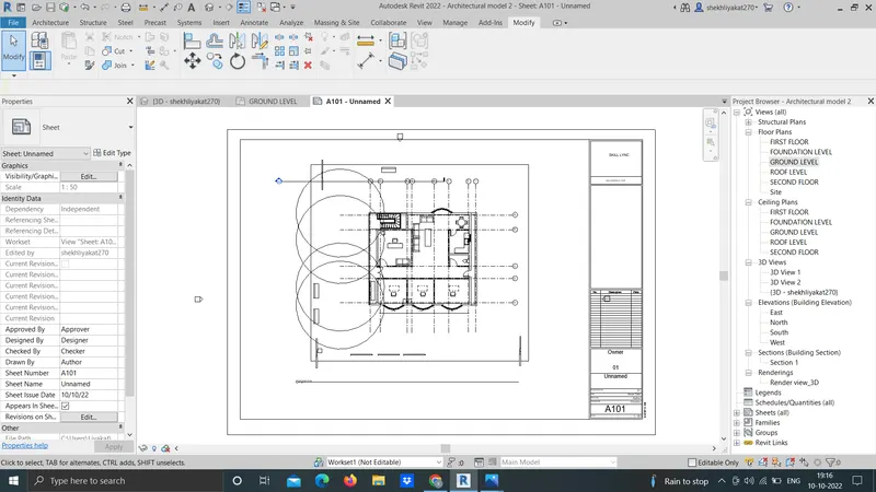
Click to place the view.Using the same method, drag theplan view to the sheet, and place it in the sheet.
RESULT:
I understood how create set of drawing in revit software.
PLAN VIEW:
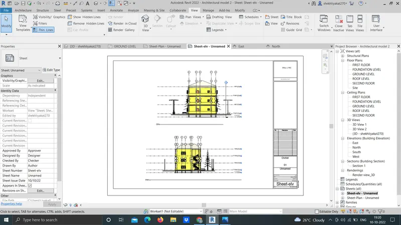
ELEVATION VIEW:
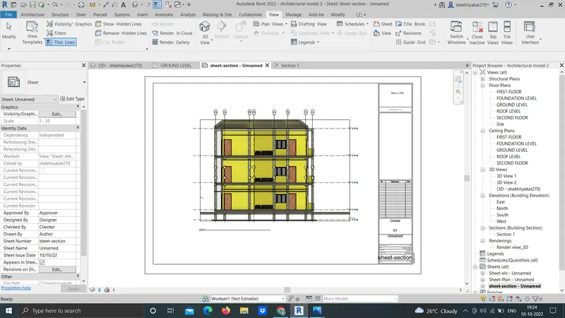
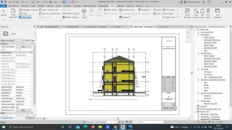
SECTIONAL VIEW
6.0
AIM: To render model in different view and add to sheet.
INTRODUCITON:
In this project, the procedure of desning of building is done from start to end.
Generally architectural engineer work on project 1st and then structural and then MEP dicipline engineer work on project.
Information regarding how model architectural elements, structural elements and how to use collabration is done very spefic in this project.
PROCEDURE:
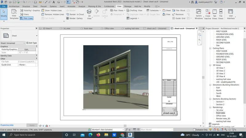
After preparing the 3D view and using the Rendering dialog to select desired settings.
Click Render to render the image.
RESULT:
Rendering of certain views are added in sheets.
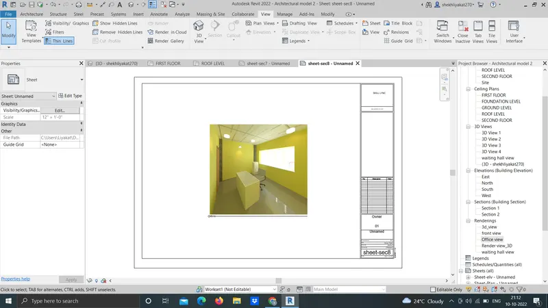
Office cabin
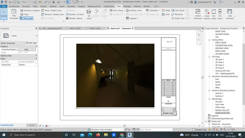
Waiting room
Topographic features
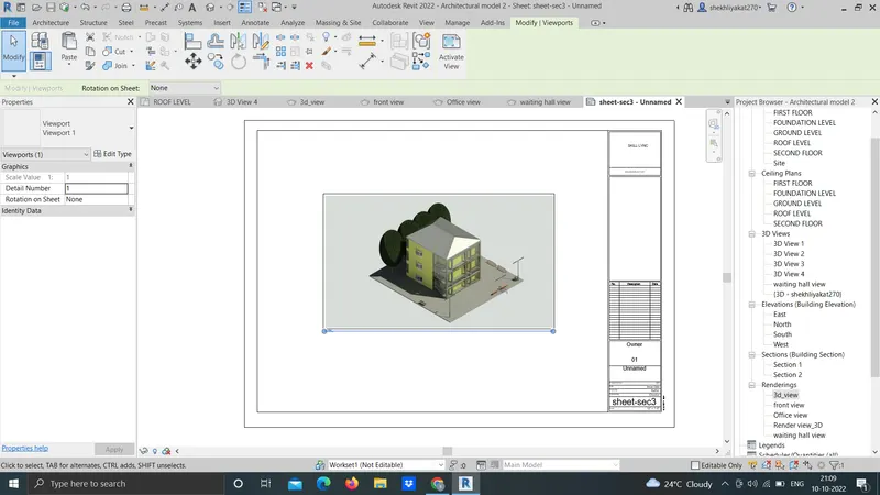
Through structural framing
Beams and columns are visible
7.0
AIM: To copy or save the pdf sheet or different view on paper.
INTRODUCITON:
In this project, the procedure of desning of building is done from start to end.
Generally architectural engineer work on project 1st and then structural and then MEP dicipline engineer work on project.
Information regarding how model architectural elements, structural elements and how to use collabration is done very spefic in this project.
PROCEDURE:
- Click File tab>Print
- In the Print dialog, for Name, select a printer.
- Click Properties to configure the printer.
- Select Print to File. You can save the print job as a PRN or PLT file.
To print to PDF, do not use this option. Instead, select a PDF print driver in the Name field
RESULT:
Sheets are printed sucessfully.