Creating Architectural and Structural model with 3D rendering using REVIT
1. Ans :
- I have created the model in Multi - Unit residential Apartment
2. Ans :
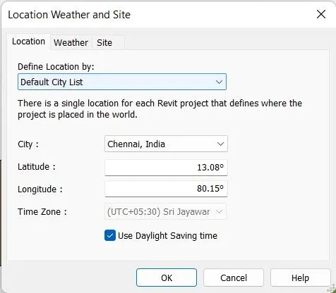
- The building is located in chennai of 32*28.6 m that is 950 m2
- This FAR valve for business building is 2.9
- Hence it is prescribed limits as per NBC.
- The width of the road adutting the building is 9 m .
3. Ans :
Aim :
- Using the structural model, include the following components based on the type of structure selected
a. Foundation – Isolated / Wall/Matt Foundation
b. Columns
c. Beams Connected to Columns
d. Roof Framing/ Truss
e. Floor / Decks
f. Floor Openings for Elevators and Stairs
Introduction :
- Before starting the diagram we have to create the Structrural template for executing the diagram.
- Once created then Assing grids and levels for the diagram
- Once assign the above process the we are ready to draw.
Procedure :
- The grids lines are created in the Footing plan in floor plans.
- Select the Isolated Footing from the structural tab and select by GRIDS in the manage tap
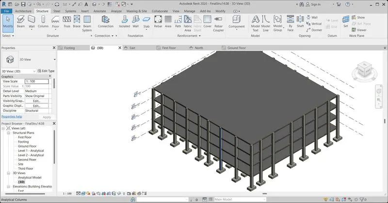
- Once the grids are selected by clicking the mouse and select the floor plan and press enter the specified concrete Footing with dimensions of 1800*2450 mm will be appeared inthe diagram in all junctions of the grids
- Same procedure for the column also once selected the column in structural tab and select by grids and column with requied size will be appeared in the diagram grids.
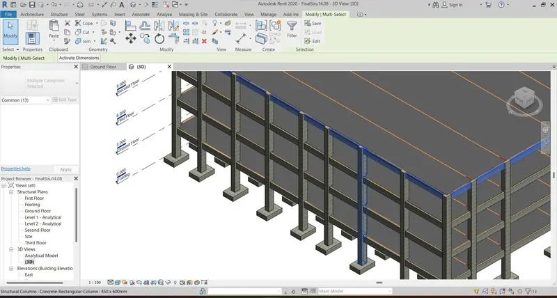
- The column can be modified by selecting overall columns and change the property of BOTTOM BASE TO FOOTING LEVEL AND TOP BASE TO 3DR FLOOR.
- Hence the column will assign to 3dr floor.
- For BEAMS select the floor plans of any one of the diagram and make connection for all columns and the beams will be appread .
- This is the same process for the Roof and Floor .
- For ELECSTOR and STAIRS select the structural tab.
- Click shaft opening Tab and select the selection type like by lines or draw lines etc....
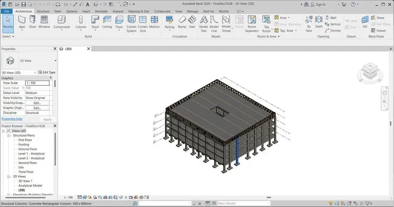
- Once it drawn with close structure we can select the properties by top leve upto third floor and bottom as ground floor once clicking it the opening will be appeared it the diagram.
Result :
- HEnce the above all structural diagrams are drawn successfully by using some revit commands like grids,level,foundation , beam ,columns , flooring , shaft opening etc..
4. Ans :
Aim:
- Using the architectural model, include the following components based on the type of structure selected
a. Wall Layout with appropriate material and finishing
b. Exterior façade with fancy finish
c. Interior partition walls to size rooms
d. Components to add details to a room ( Desk, Chair, Lighting, Plumbing fixtures)
e. Add components such as stairs Elevators
f. Have at-least one side of the building with curtain walls and glass panels
g. Include interior and exterior lighting fixtures
h. Place proper topographic components from outside ( Trees, Parking, Plants) to add details to the model.
Introduction :
- Before starting the diagram we have to create the Architectural template for executing the diagram.
- Once created then Assing grids and levels for the diagram
- Once assign the above process the we are ready to draw.
- OR else we can load the structural diagram in the revit using revit links or in manage tab click manage link and load the structural links of the project.
Procedure :
- Once the structural done we have to do the Architectural work select the floor plans and started doing the wall and other finishing .
- Select the wall command in architectural tab and select wall and draw the lines of the wall outer and then wall is created.
- Select the floor plans like ground floor and make partions for the room and allign with the external components.
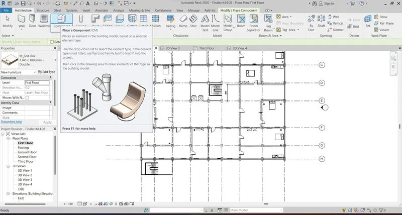
- Once the Building internal rooms are divided then add the components like beds , tv, sofa , kitchen model etc.....
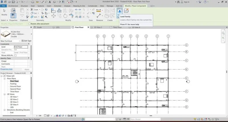
- By clicking component in the architectural tab and load the family of what are the components required to view more relastic view of the building .
- Once the following procedure we have to assign the staircse and escalator .
- By selecting the components we can load family and insert the lift .
- The staircase can be drawn using staricase command in the architectural tab and draw from selecting the levels from ground floor to first floor.
- Once done with staricase we can copy and assign to other levels.
- Lighting will be avaliable in the load family.
- For placing the topographic component select massing and site tab.
- Click the toposurface and make the ground by selecting points.
Result :
- From the above procedure all the diagrams are drawn in architectural template and make the building more releastic view.
5. Ans :
AIM :
- From the a procedure we can create the floor plans and elecation and section in sheet.
Procedure :
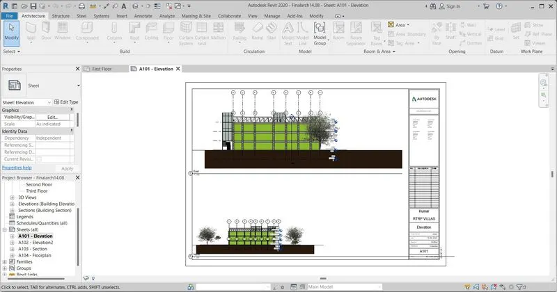
- Once the diagram is create we can select the view TAB and select the sheet and pick the A1.
- Then the A1 sheet will be appear the by selecting VIEW button in VIEW TAB we can add the certain diagrams to the given sheets which for view purpose and printout.
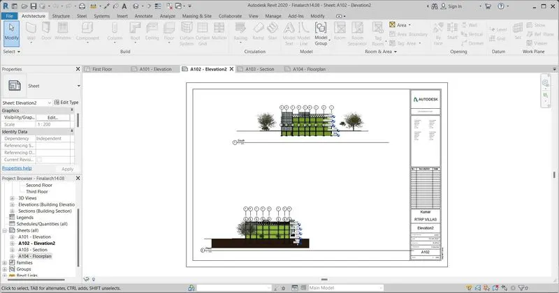
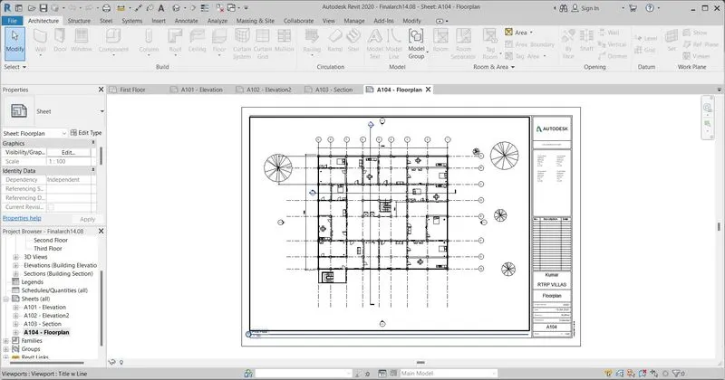
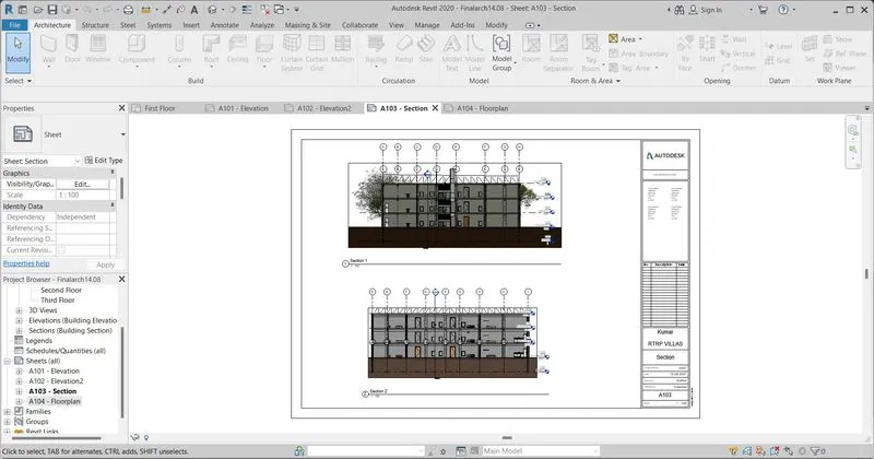
Result :
- From above procedure all diagram are drawn and view in the sheets for the further purpose.
6. Ans :
AIM :
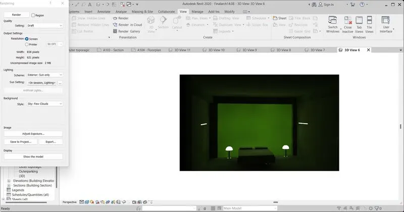
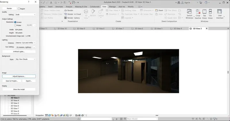
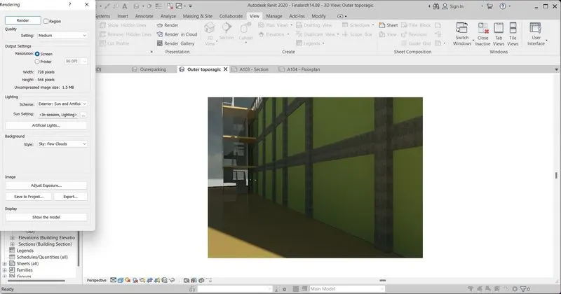
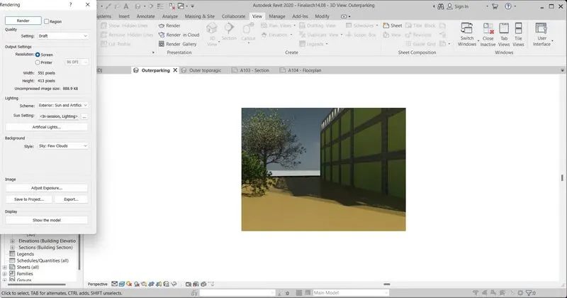
- Using the Rendering settings, Render images of the 3D model produced and include the rendered images to the drawing sheets
a. Rendering from interior rooms
b. Rendering from out showing topographic features
c. Rendering through structural framing.
Procedure :
- Once the diagrams with all views are created we can create the camera veiw to view the each room and topography strucute view etc .
- Select the Floor plan and select the view TAB and select the 3D tab in which select the camera.
- Once the camera is selected we can possion it on the required rooms and outer building and lift area etc.
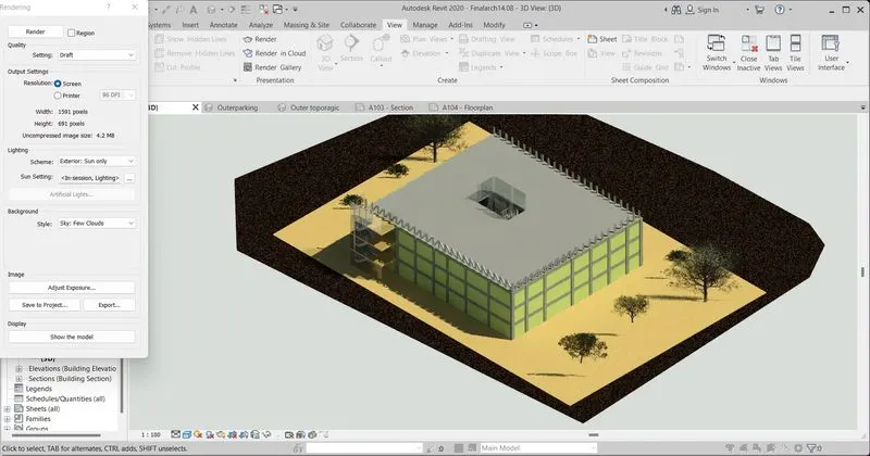
- The view can be made more realistc by using render command on the view TAB.
- Once select the render Tab and it shows the setting for the render view which we can change the sun light etc and brightness etc.
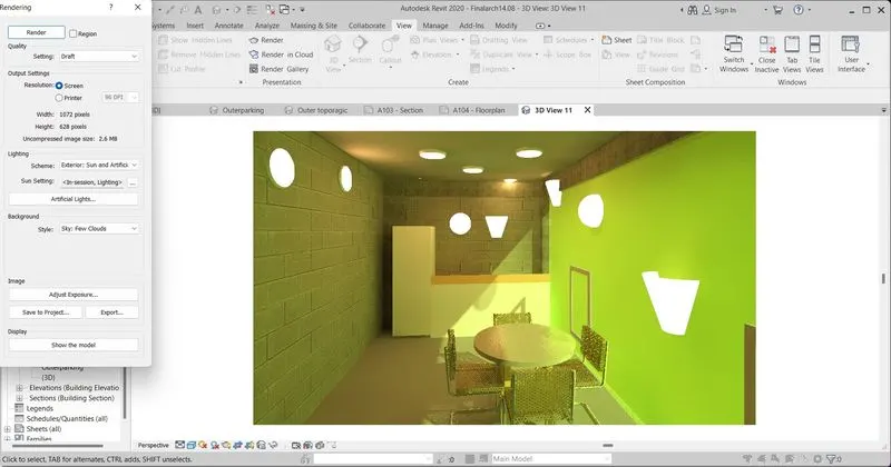
Result :
- Hence the rendering for all view and rooms are place in the diagrams are created using render command.
7. Ans :
Aim :
- To print the following sheets in Revit using command.
Procedure :
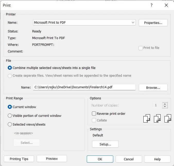
- Once all the diagrams are created and sheets are created if you want to get printout of the all sheets we can get it done using revit PRINT option.
- Select the Required diagram which has to be print and select CONTROL + P.
- The print dialog box will appear which we can select the type of the printer.
- We can Modify the paper setting to A0 to A4 etc .. what ever required and we can change the number of prints required etc.
Result :
- By using revit we can print the documnet as well we can use locally be creating PDF file also so hence printing command done.