Creating Architectural and Structural model with 3D rendering using REVIT
Aim: Creating architectural and structural model with 3D rendering using revit
Introduction: Autodesk Revit is a BIM tool, which can be used by more than one person working on a new project. This is an important feature in colloboration within a project, between projects, and with other users, firms, and disciplines.
Colloboration tools guide is to enable us, who have a basic knowledge of Autodesk revit, to increase their productivity while working with other people on a team, either in the same firm or other firms as well as with other disciplines. It also covers linking Autodesk Revit files and linking or importing other CAD files. Practices are avilable for each of the primary disciplines covered by Autodesk Revit: architecture, MEP, and structure
Revit provides several different ways to colloborate with team members who are also using the software
We can link multiple revit model together, allowing team members to work in context.
Through worksharing, users on the same local area network(LAN) can work together in the same Revit model.
When colloboration needs to occur among users who are not in the same geographic location, use revit server or revit cloud worksharing
Revit server connects offices who share a network but are not in the same geographic location
Revit cloud worksharing is a cloud based service that allows any revit users inside or outside a network to colloborate on a revit model
1) I choose office building for this project
2) The office building is planned to be constructed in Kochi
Modelling requirements as per NBC
Since, my building is an office building, it can be taken as a business building
The open space around the building shall not be less than 4.5m
Considering the type of construction as type 2 construction, the FAR value for the business building shall be taken as 2.9. The plot size is taken as 40mx70m. i,e, 2800m2 and individual floor area is 2000m2. Hence, FAR value obtained is 2.14 which is within the prescribed limits as per NBC
The width of the road abutting the building is taken as 30'
The maximum height of the building shall not exceed 1.5 times the width of road abutting plus the front open space
Building will consist of 7floors each floor having a floor height of 15'. Hence, the entire floor height will be 90' which is within the limits prescribed by NBC
3) Procedure:
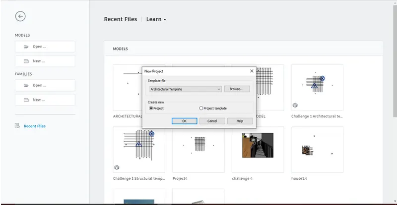
Click on the new options in the model section and select the architectural template from the new project dialogue box and click ok
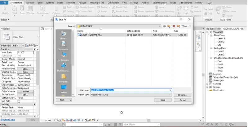
Save the files to a desired folder and was named as architectural file
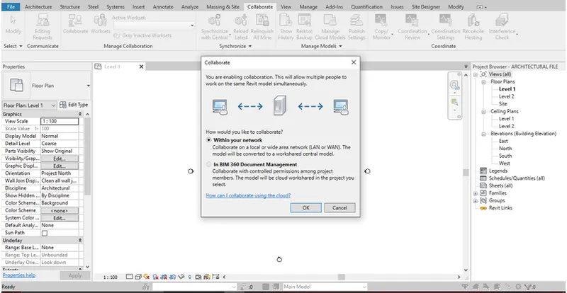
Go to colloborate tab in ribbon and click on the colloborate icon
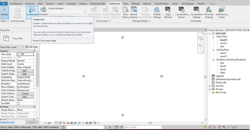
The colloborate dialogue box will appear and select within your network and click ok
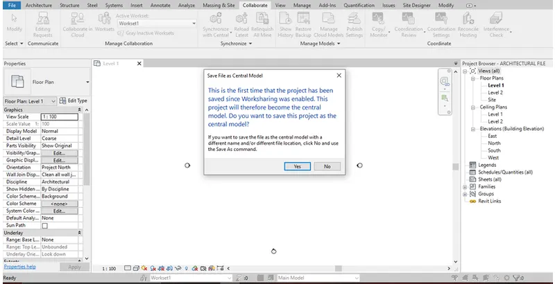
Now save the file and save it as a central model by clicking yes in the dialogue box that appeared
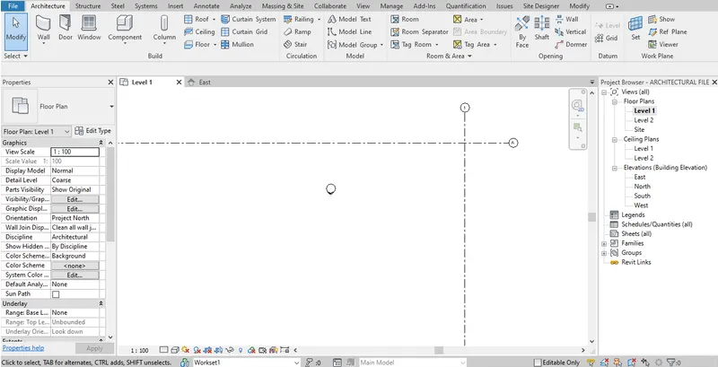
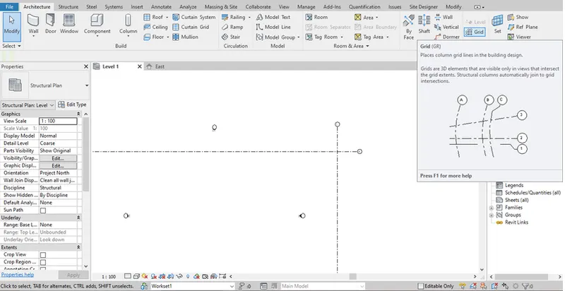
The outermost horizontal and vertical grids was now created as shown
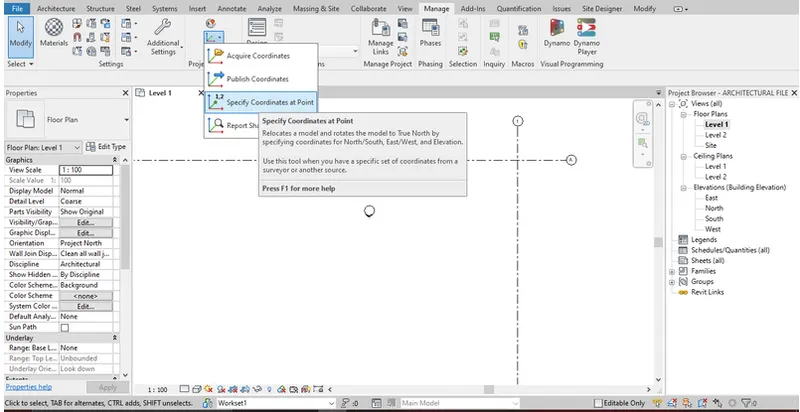
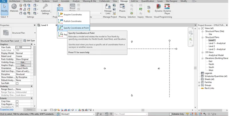
Now in the manage menu under the project location tab click on the specify coordinated at point
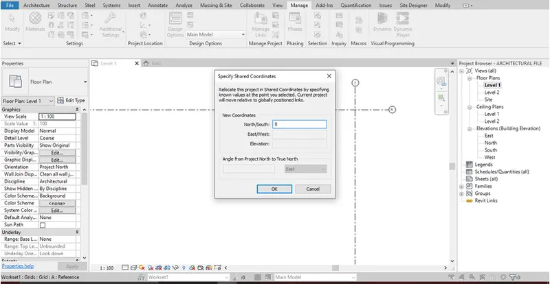
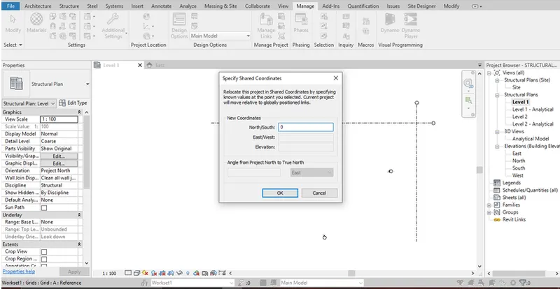
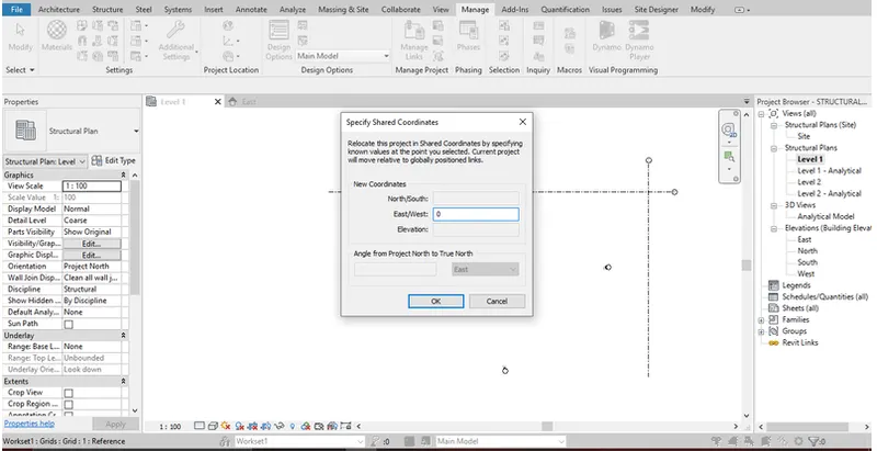
Click on the base line grid drawn to open the specify shared coordinates dialogue box and change the north/south coordinates to 0 and click ok
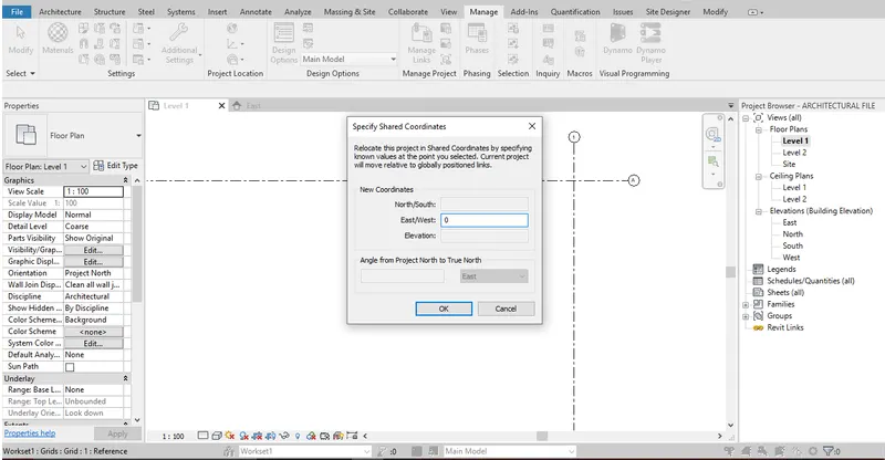
Click on the next base line grid drawn to open the specify shared coordinates dialogue box and change the east/west coordinates to 0and click ok
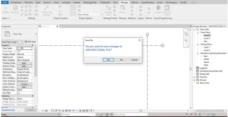
Finally save the file to a desired folder and close it
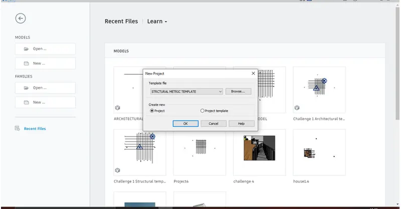
Click on the new options in the models section and select the structural template from the new project dialogue box and click ok
Finally save the file to a desired folder and was named as structural file
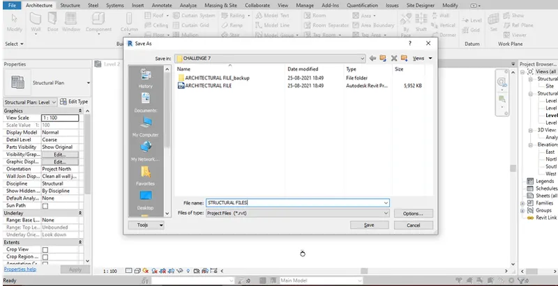
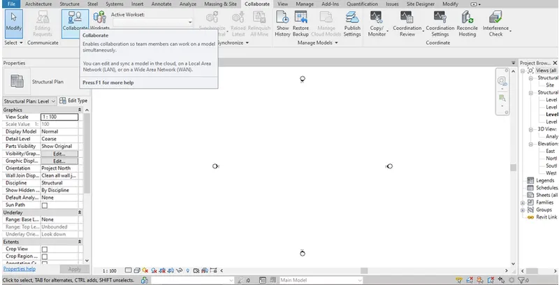
Go to colloborate tab in ribbon and click on the colloboration icon
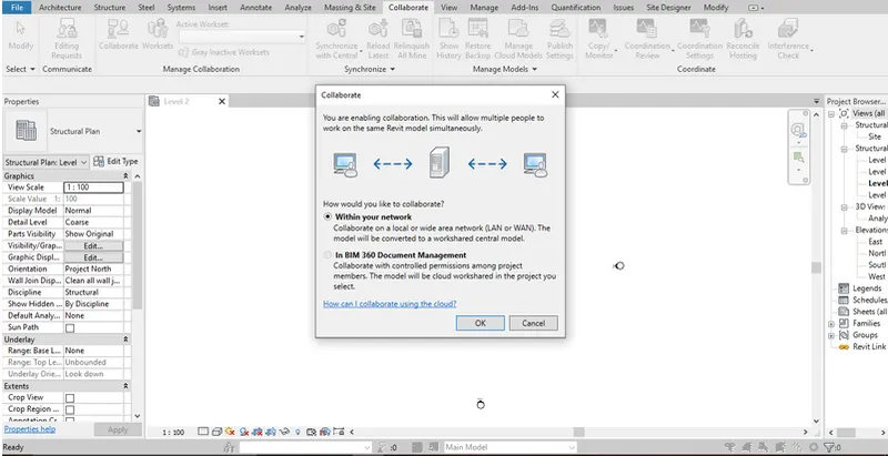
The colloborate dialogue box will appear and select within your network and click ok
Now click yes to save the file
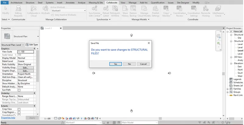
Save it as a central model by clicking yes in the dialogue box that appeared
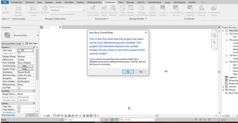
The outermost horizontal and vertical grids was now created as shown
Now in the manage menu under the project location tab click on the specify coordinates at point
Click on one base line grid drawn to open the specify shared coordinates dialogue box and change the North/South coordinate to 0and click ok
Click on the next base line grid drawn to open the specify shared coordinates dialogue box and change the East/West coordinate to 0and click ok
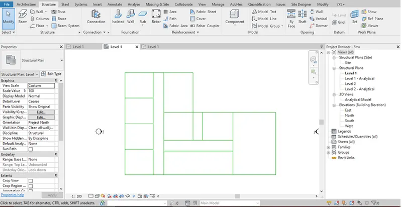
Using the model line a model of the office building was Created as shown in the level 1
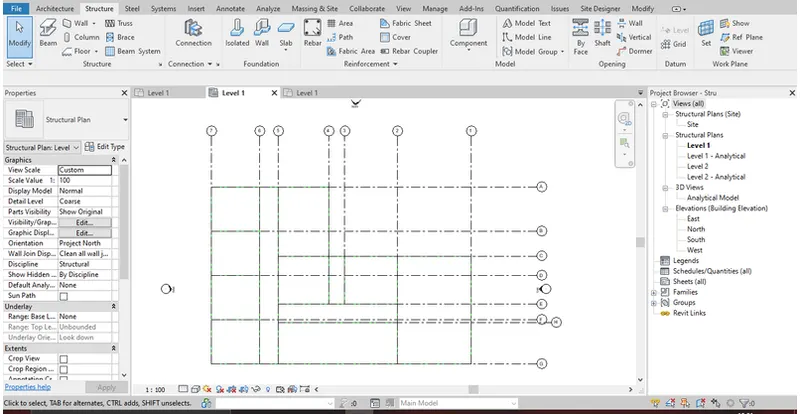
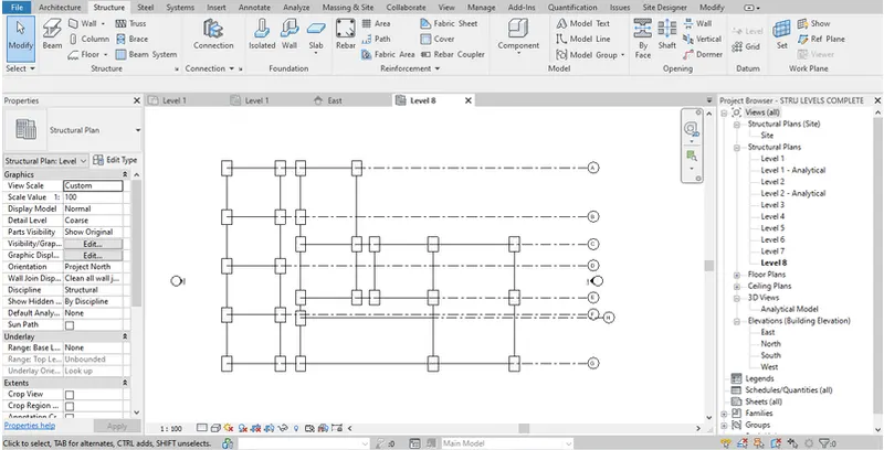
All the horizontal and vertical grids was created as shown. Horizontal grids are named from 1to 7 starting from right to left and vertical grids named from Ato G starting from top to bottom
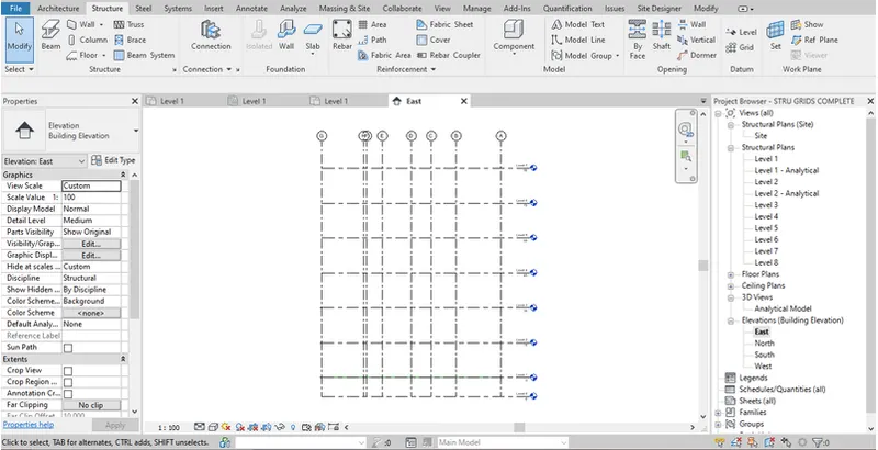
By using the levels option in the structure tab 8 levels was created at a height of 15' each and foundation level at a depth of 8'
Click on the isolated footing option in the structure tab to apply footings to the building
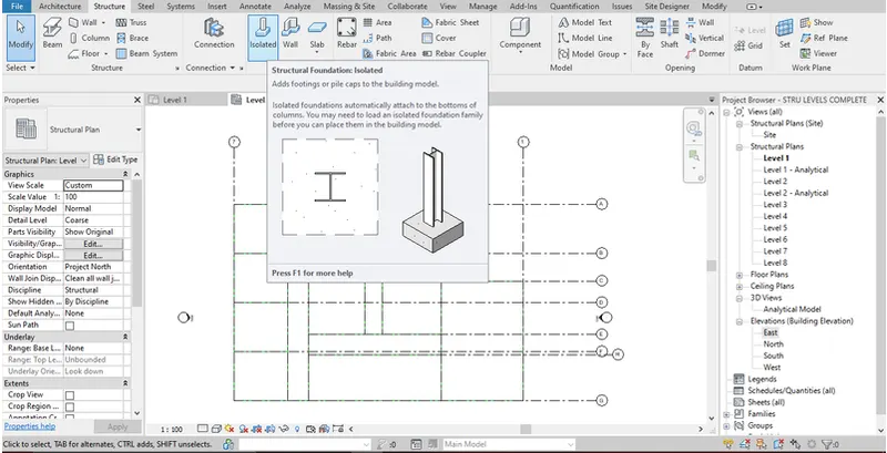
All the footings was placed at the intersection of vertical and horizontal grids as needed
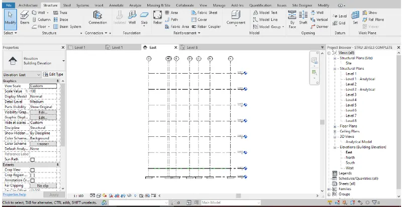
The east elevation view showing the footings are provided below. From figure we can understand that all the footings are correctly aligned
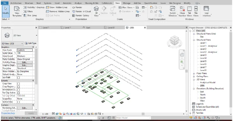
The 3D view of the same is as shown. The green line is the model line which we created earlier, as it was created in the level 1 and as the foundation is at level 8 it shows that irregularity
Click on the column option in the structural tab to draw the columns now
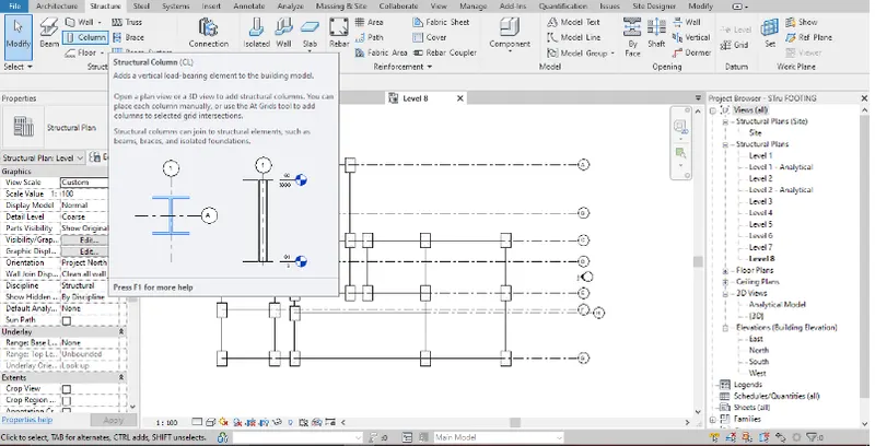
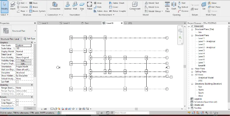
Now all the columns are placed at the centre position in top of the isolated footing till the ground floor level that is till level 1
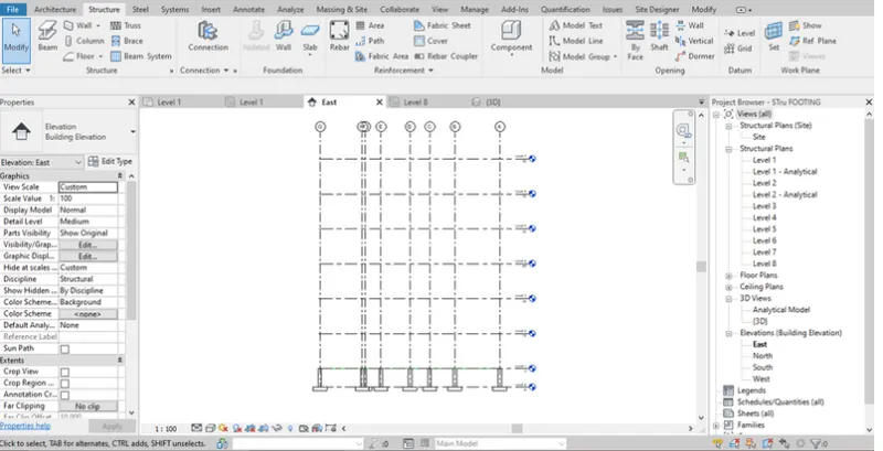
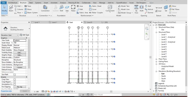
The east elevation view showing the columns are provided correctly on top of the footings
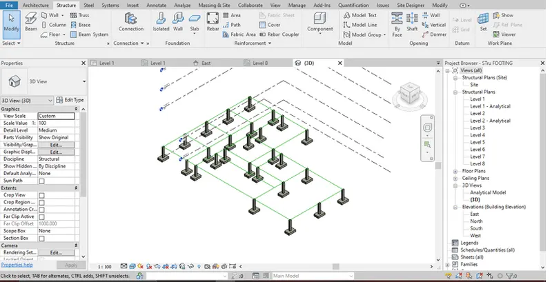
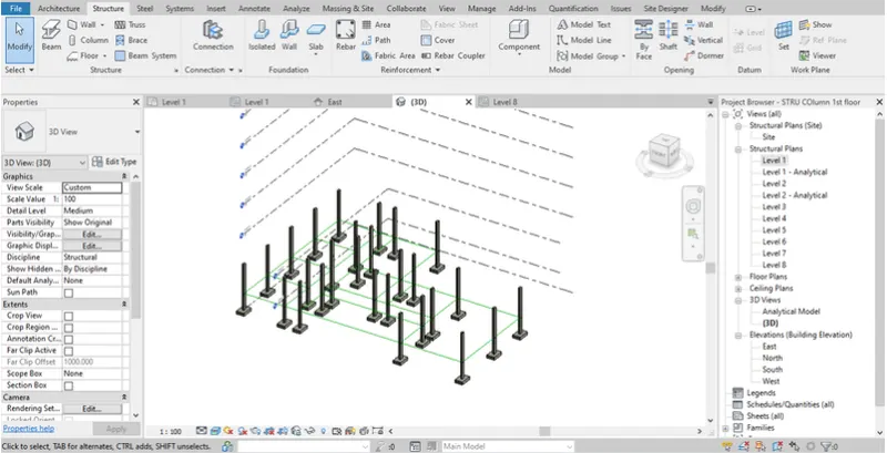
The 3D view of the same is as shown. The green line is the model line which we created earlier, as it was created in the level 1 and as the column is constrained at level 1 now it is alligned correctly
Now in the similar way the columns are placed at level 1 to level 2 using the at grids option. For this just select all the grid lines, assign the top and bottom constraints and click ok. This is the easiest way of placing columns accoding to me
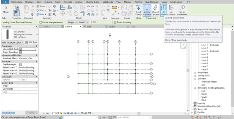
The east elevation view showing the columns are provided correctly
The 3D view of the same is as shown
The beams are placed next using the on Grids options. Click on the beam option in structure and select the beam of our choice and select on grids option. Now select all the grids lines and click ok
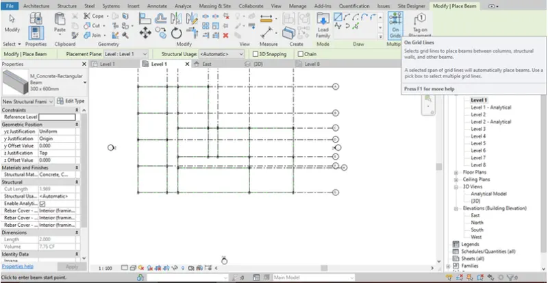
The beam is now properly arranged and placed at required places as shown
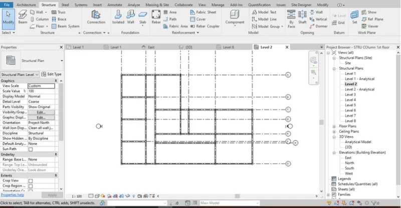
The east elevation view showing that the beams are provided correctly
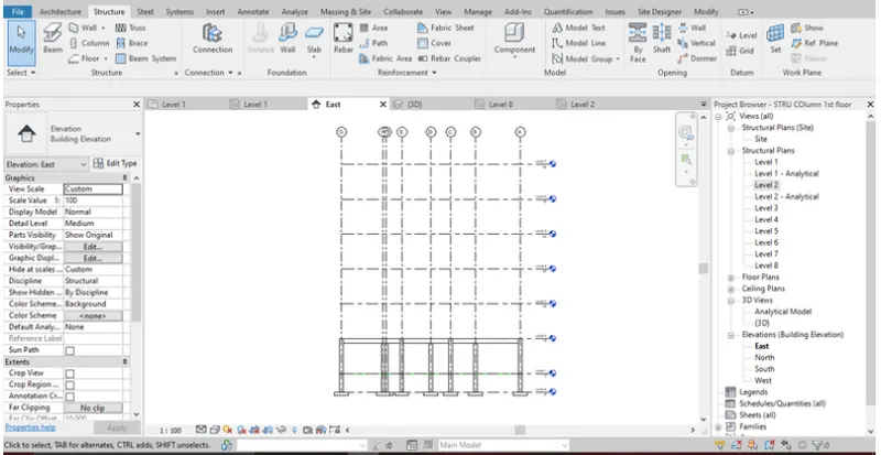
The 3D view of the same is as shown
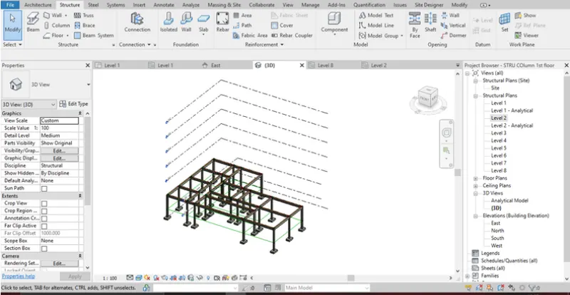
Now select all the components that is the beams and columns of a level and copy it to clipboard using the copy option
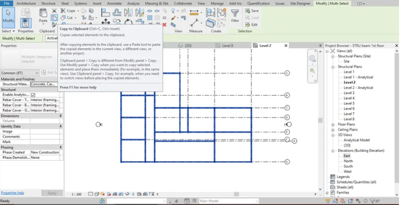
Now paste the copied components and select the required levels using the paste to required levels as shown
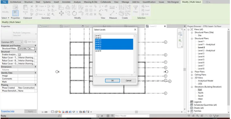
The east elevation view showing that the copy paste operation was successfully executed
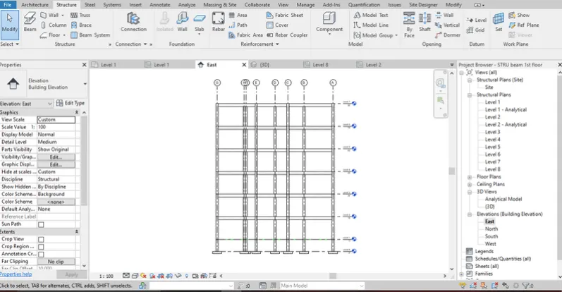
The 3D view of the same is as shown
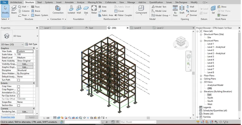
d) The next task is to provide a roof to the structure
Here a flat roof is provided as shown
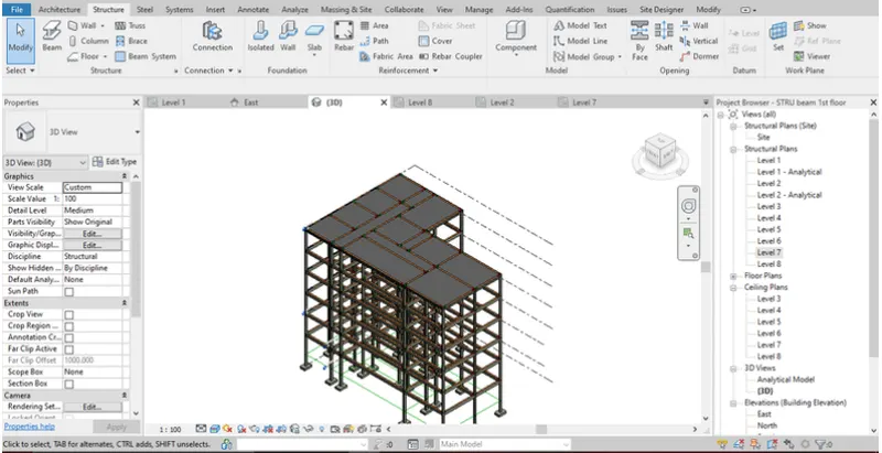
e) Strutural floors
Click on the structural floor option in the structural tab as shown
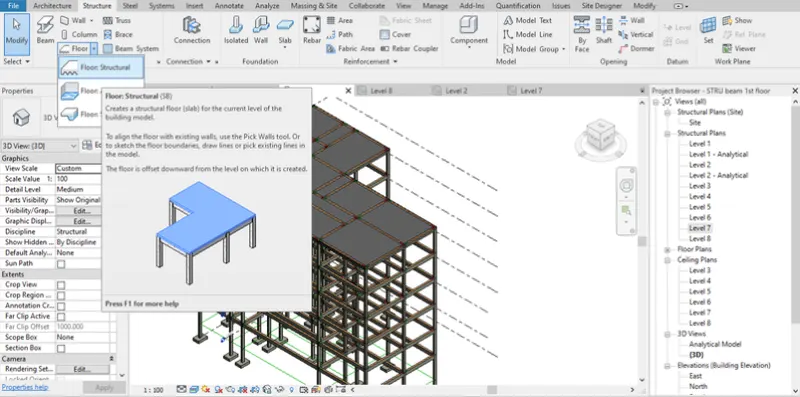
Initially draw the structural floor in the ground floor and then copy paste it to the remaining levels as shown
f) Shaft openings
Click on the shaft opening options in the structure tab. Using the line option drwn the opening portion for the shaft and select the required levels
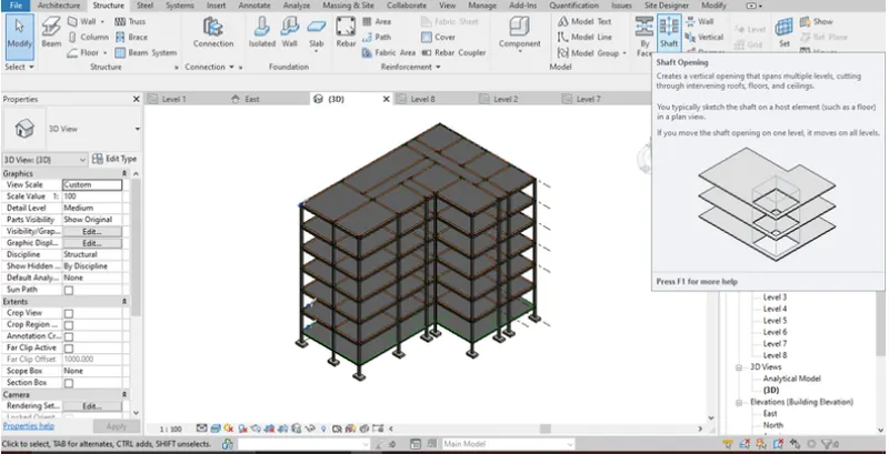
The shaft opening is provided till the level 2 and is as shown in the 3D view
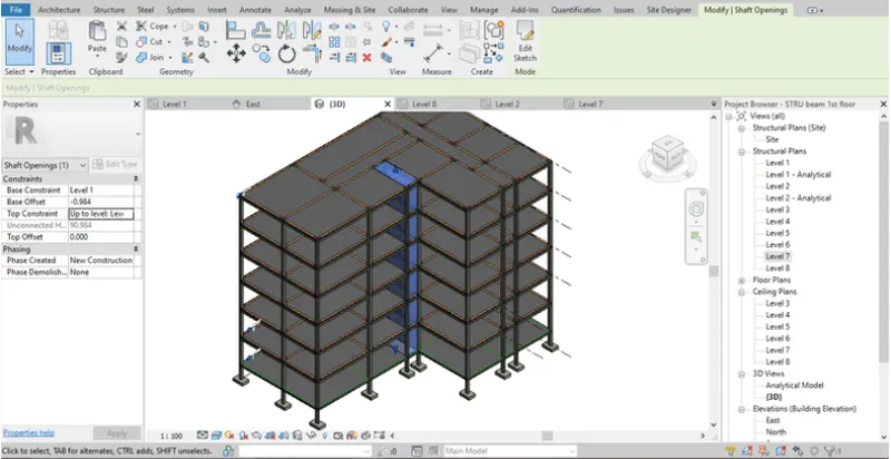
Results: Structural components like footings, columns, beams, roofs, structural floor, and shaft openings was provided
4) Procedure:
Initially, we have to link the architectural and strutural template
For this, first open architectural template and then insert the strutural template into it
For this, go to insert tab---->revit links---->choose the links
Using the copy monitor copy all the components to structural template
Now the architectural model and structural model is linked
a) Wall layout with appropriate material and finishing
Wall layout has been developed. Wall thicknes provided is 200mm. Now, we have to assign the material to the wall, Here, wall is available only in the three fourth portion rest is provided as curtain wall
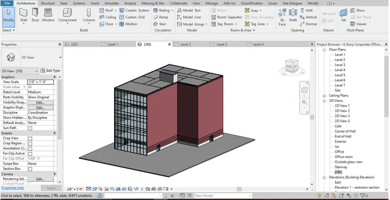
Material provided for the wall is brick and CMU
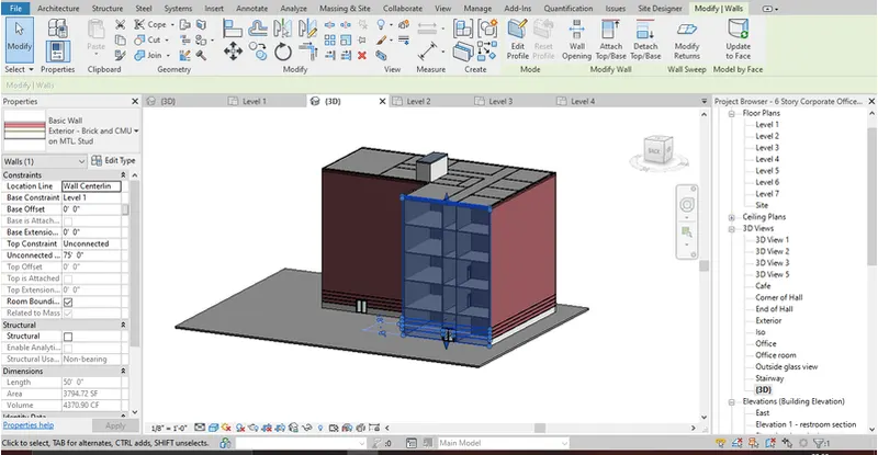
After the wall is designed all the necessary doors and windows was provided in the exterior wall as shown
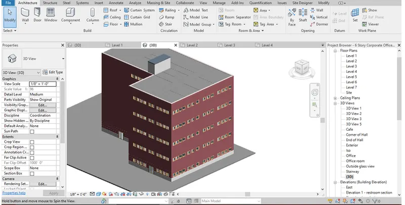
b) Exterior facade with fancy finish
Exterior facade with fancy finish was provided as shown
c) Interior partition walls to size rooms
The interior partition walls was provided next as shown
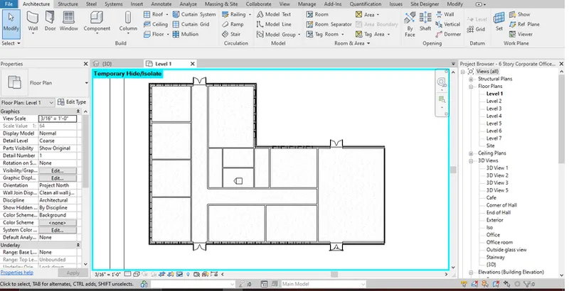
All the openings and doors required was also provided as shown
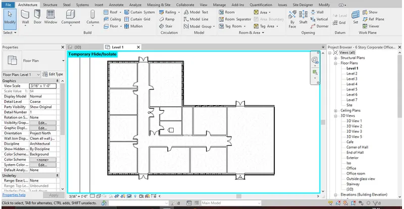
d) Components to add details to a room ( desk, chair, lighting, plumbing fixtures)
This can be provided by going to architectural tab---> Components---> load family---> and then place the required components at the required locations
The same layout is followed till the level 7
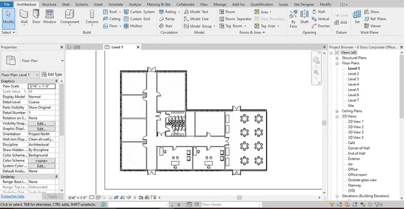
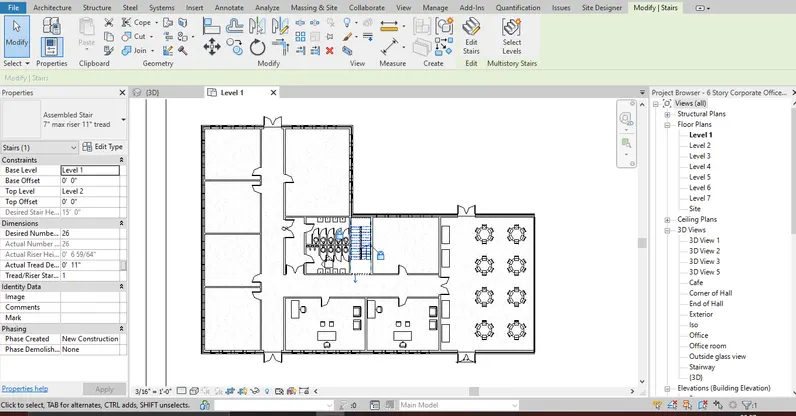
e) Add components such as stairs elevators
At the shaft opening provided earlier a straight stair was made as shown
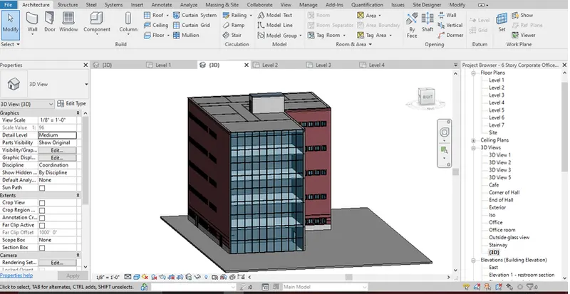
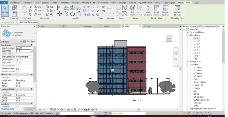
f) Have atleast one side of the building with curtain walls and glass panels
One side of the building have been assigned with the storefront curtain wall as shown
g) Include interior and exterior lighting fixtures
exterior:
Exterior lighting fixtures was provided as shown by going to architecture tab---> components---> load family---> and then place the exterior light components at the required locations
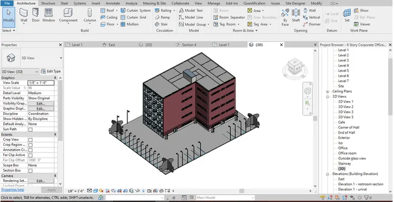
Interior:
In the similar manner internal lightings was also provided as shown
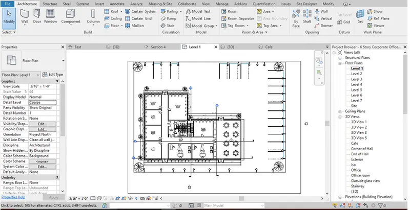
h) Place proper topographic components from outside (Trees, parking, plants) to add details to the model
For this, go to architectural tab---> components load family---> select plantings and place shrubs and other plants
Already while providing the lighting itself all the topographic components was placed at that time itself
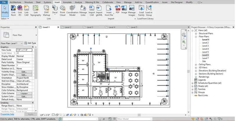
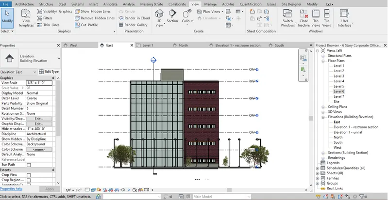
east elevation view showing most of the topographic view is as shown
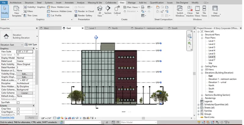
3D isometric view of the building is as shown, it shows the topographic details of the building
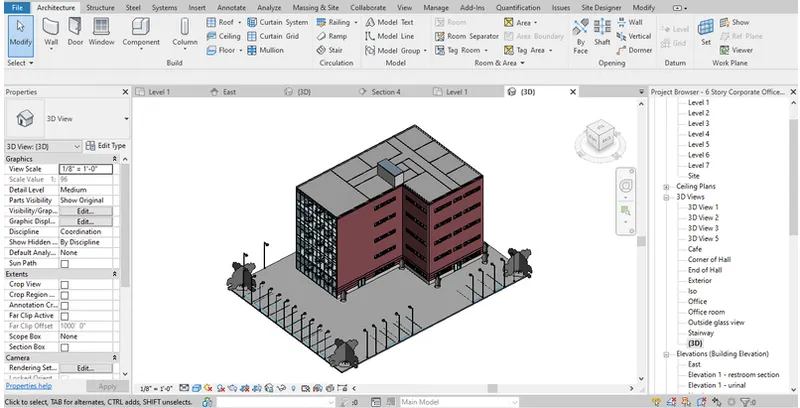
5) Procedure:
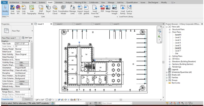
Floor Plan level 1
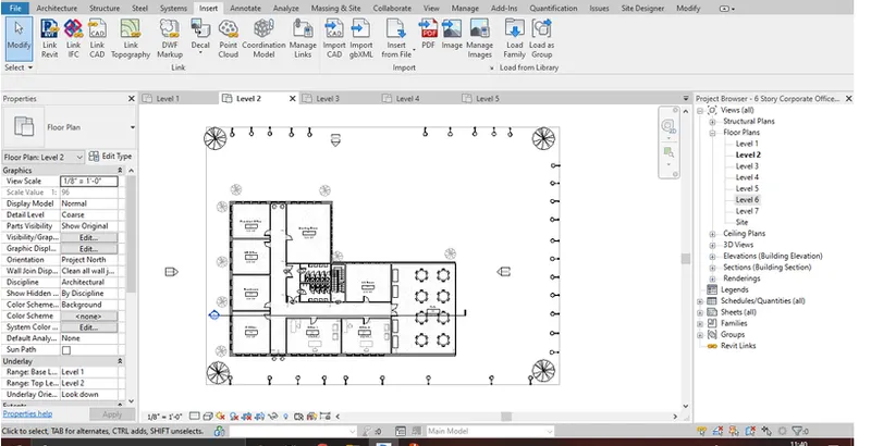
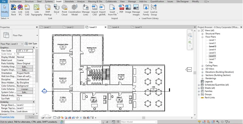
Initially all the floor plans was properly annotated as shown. It was an easy task as all the floors contains the same elements
Floor plan level2
Floor plan level 3
Templates:
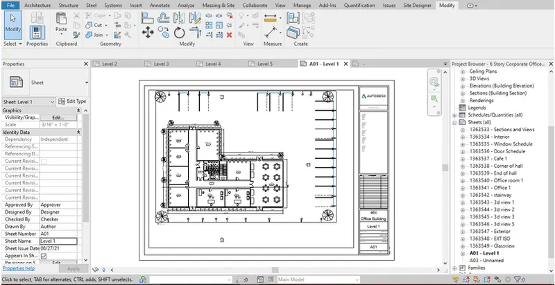
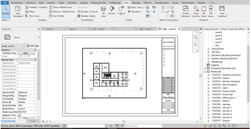
Now all the views was added to the template as shown
Floor plan level 1
Floor plan level 2
b) Elevation templates
East elevation
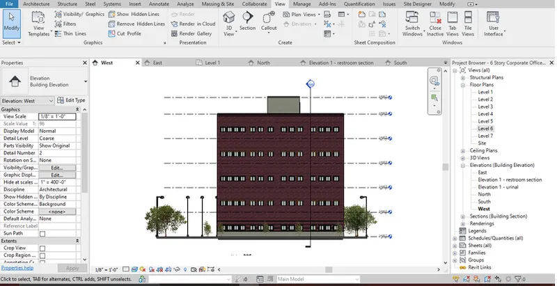
West elevation
North elevation
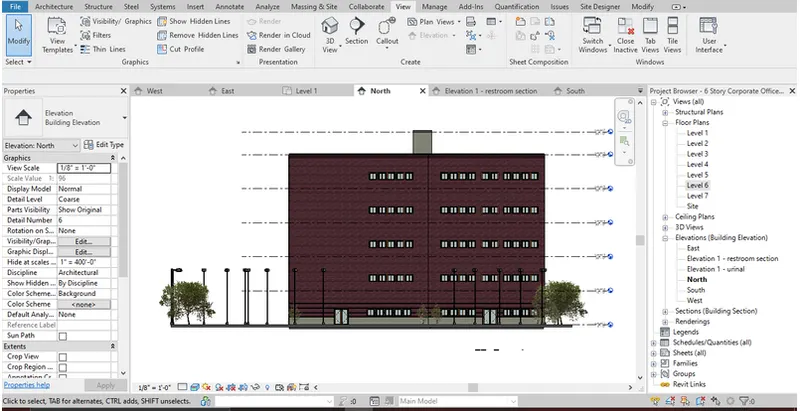
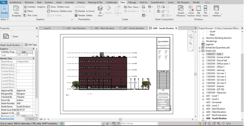
South elevation
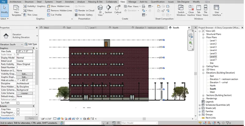
Templates:
East elevation templates
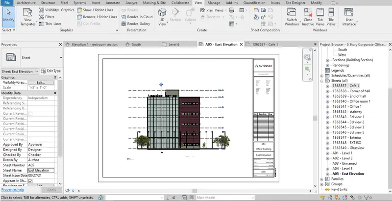
West elevation template

North elevation template
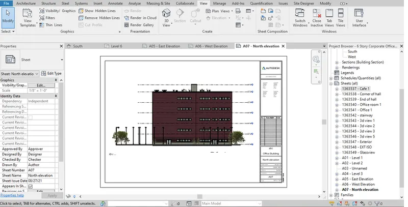
South elevation templates
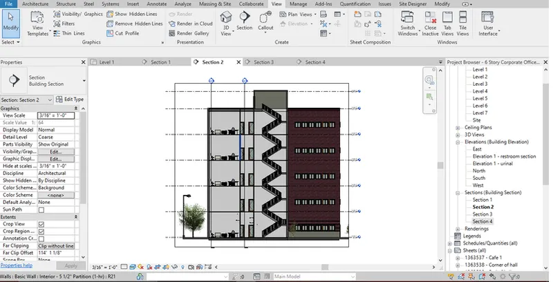
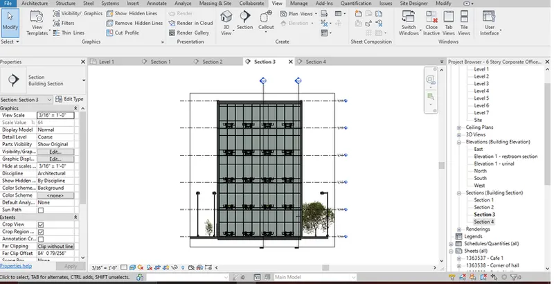
c) Sections
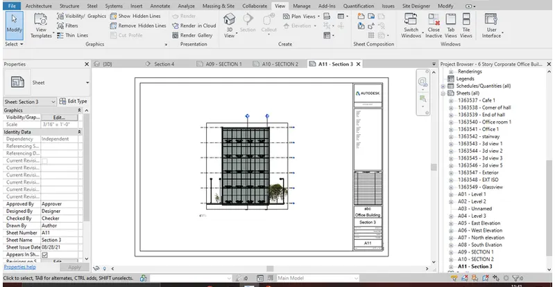
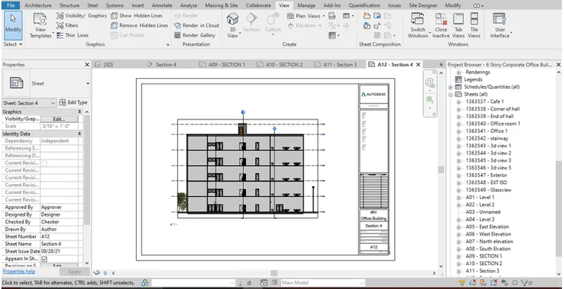
Click on the section line in view tab
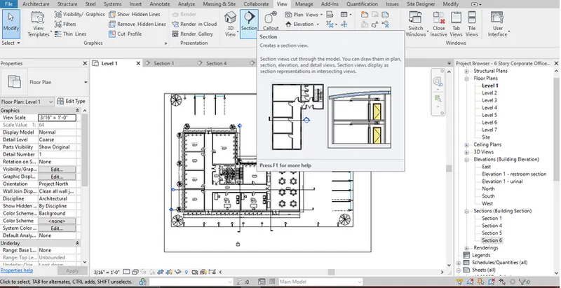
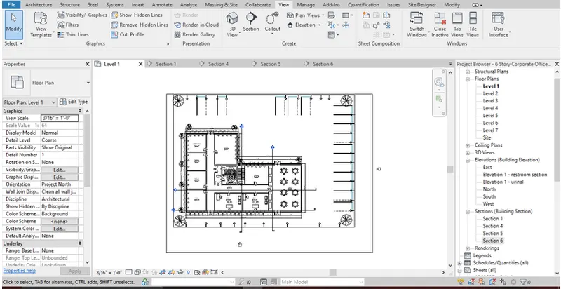
Click on the section line through the building as required
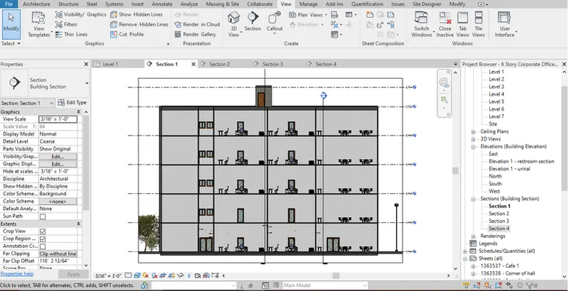
Section 1
Section 2
Section 3
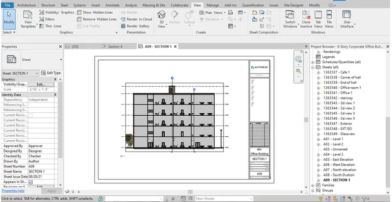
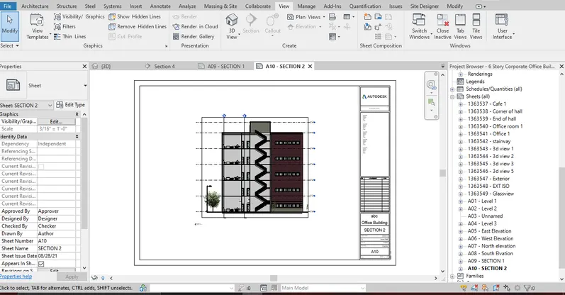
Section sheet template
Section 1 Template
Section 2 template
Section 3 template
Section 4 template
6) Procedure:
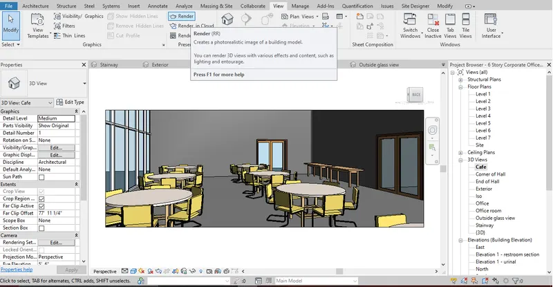
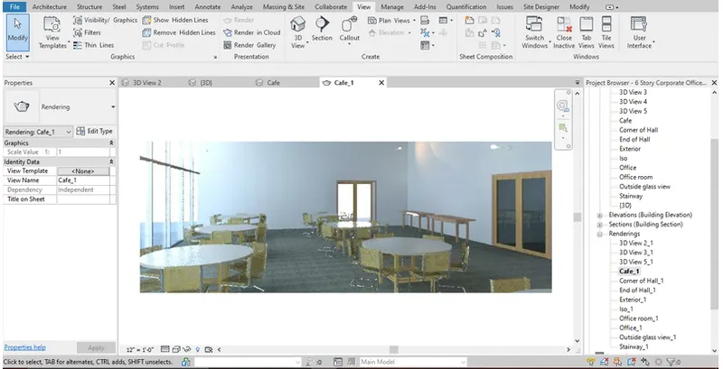
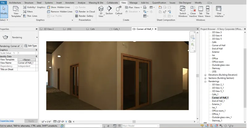
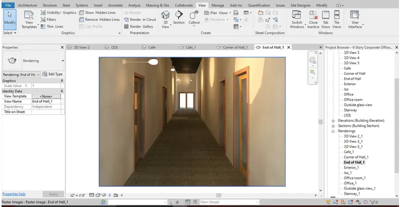
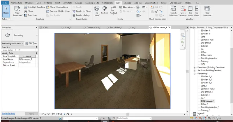
To create 3D rendered image first go to view---> 3D view----> camera
Then place the camera wherever required
Then in the view tab select render option to render the 3D image
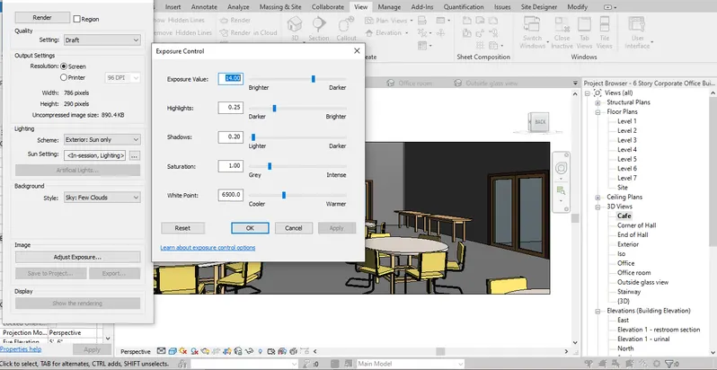
Rendering setting was modified as follows
Rendered cafe
Rendered hallway
Rendered end of hall way
Rendered office room
Rendered office room 2
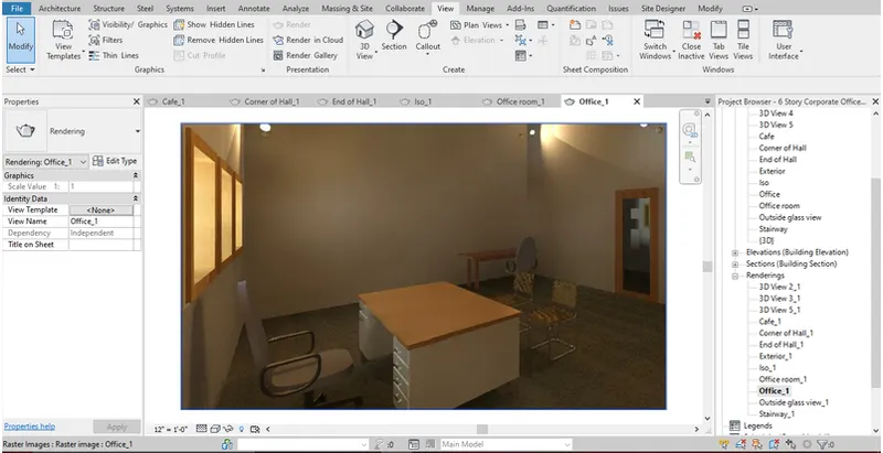
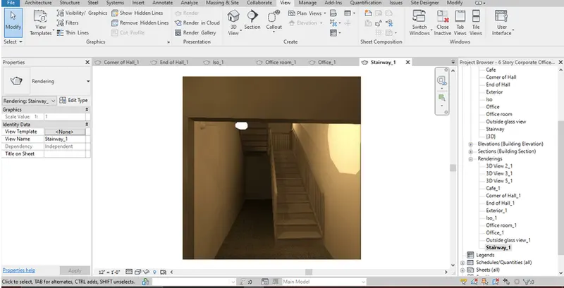
Rendered stairway
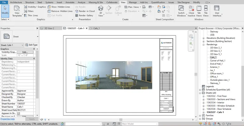
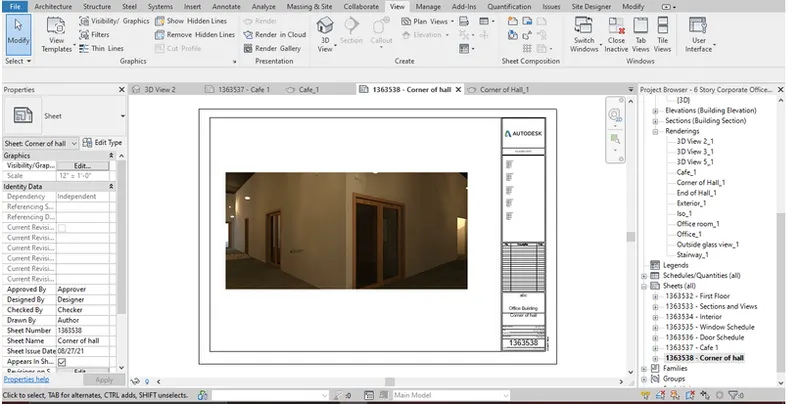
a) Rendered images was placed on the sheet template as follows.
Cafe
Hall way
End of hall way
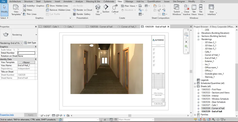
Office room
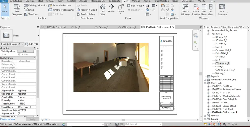
Office room 2
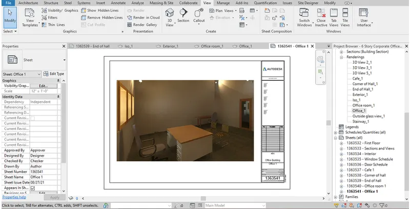
Stairway
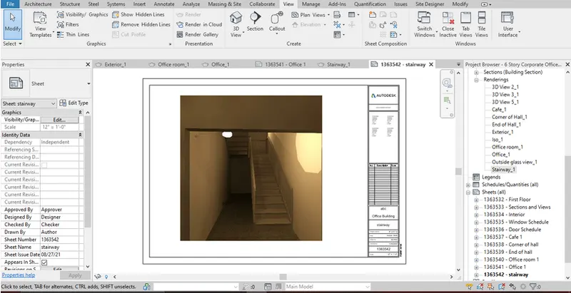
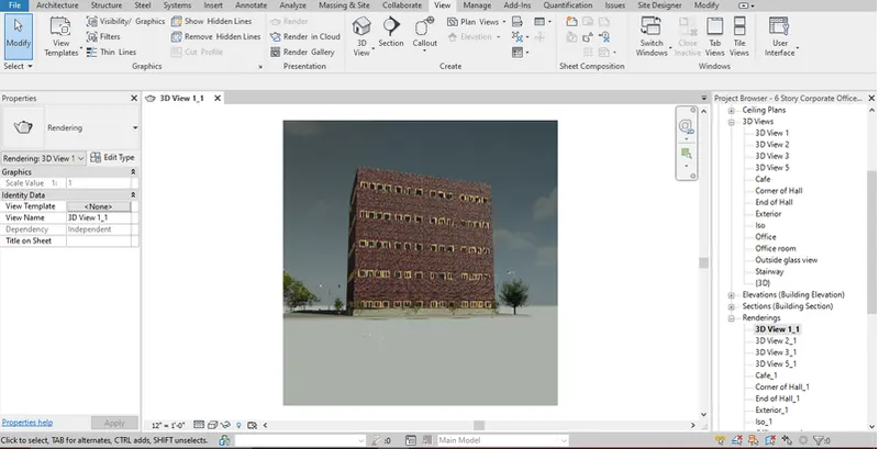
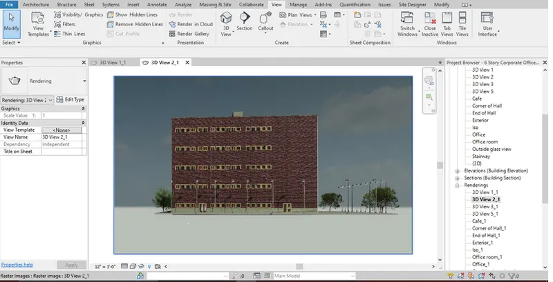
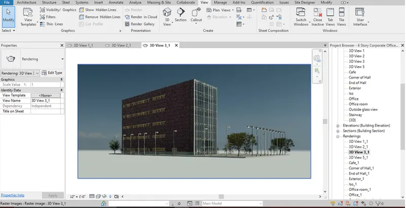
b) Outside rendering showing outside geography
3D view 1
3D view2
3D view 3
3D view 4
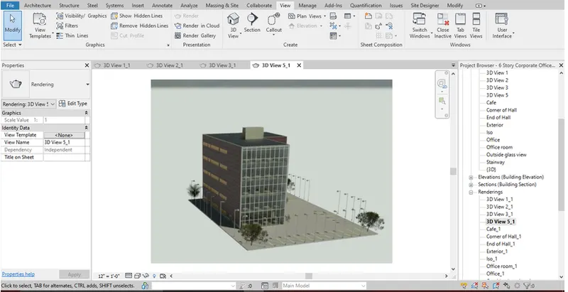
3D view 5
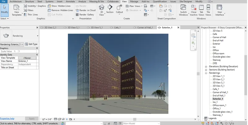
3D view 6
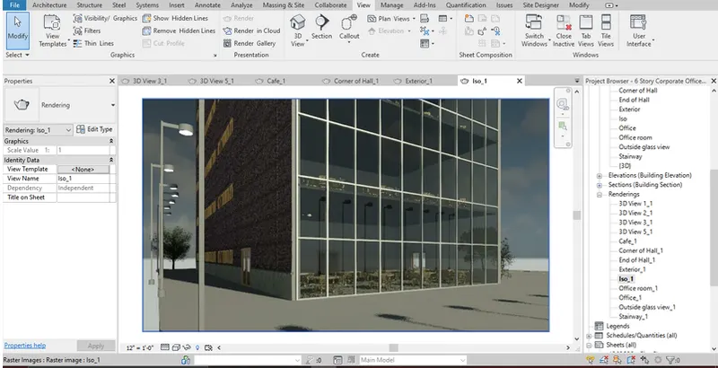
3D view 7
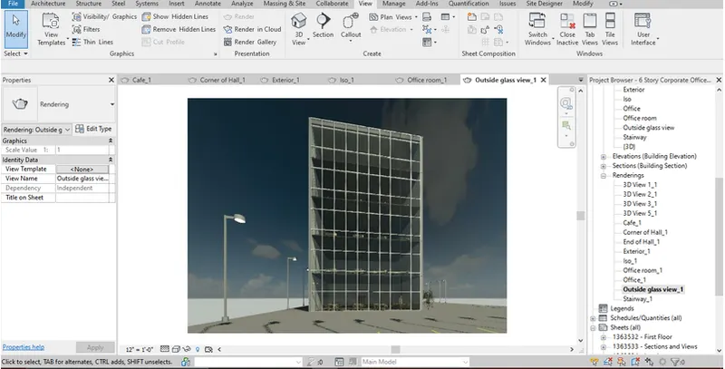
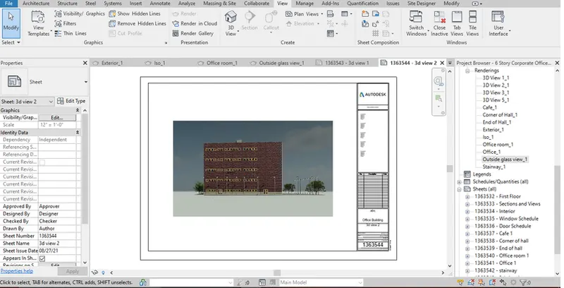
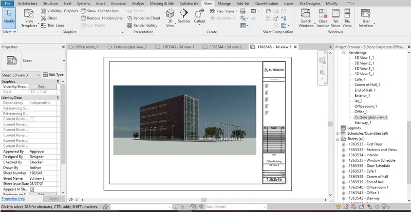
Outside view in templates
3D view 1
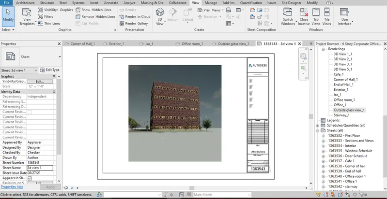
3D view 2
3D view 3
3d View 4
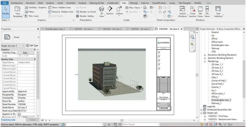
3D view 5
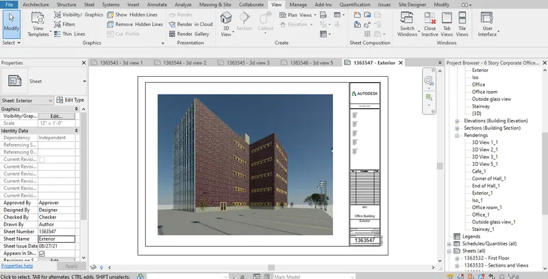
3D view 6
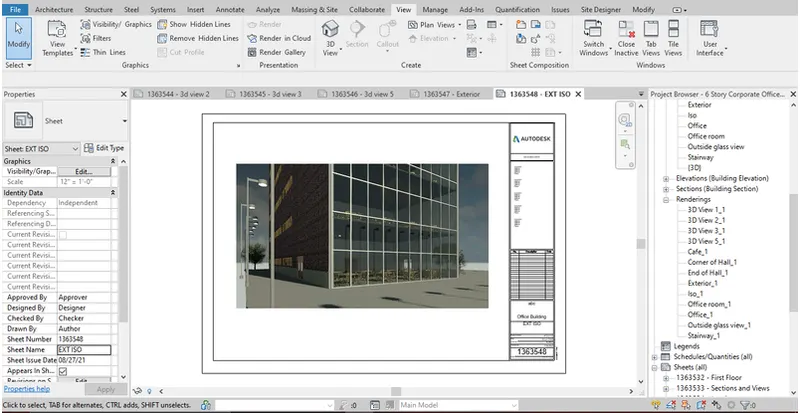
3D view 7
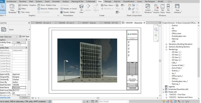
c) Rendering through structural framing
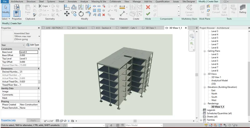
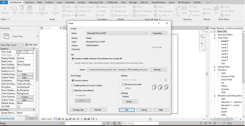
7) The different drawing templates can be printed. This can be done by going to the file menu in the top left corner of the revit window and in that choose print, then this window appears