Creating Architectural and Structural model with 3D rendering using REVIT
1)
The Structure that i want to build from the above is Multi unit Residential Apartment
2)
The assumption that i have made for geographic and loction details fpr my project modeling are:
- My assumed location details are Jublihills road no-1, Hyderabad
- My project is in plain terrain Road width in frron of apartment is 55'
The type of structure selected is Multi unit Residential unit
- My Building height is 12.8m and the roadwidth is 18.2m the height of building that can be constructed in thart place is 16.6m , the height of my building is as per NBC.
- mY structure can be construction in residential area .
- length and breadth of the room are consider as per NBC
- The fire and safty measues are followed as per NBC.
3)
AIM: To create a Structural model and including the following component like foundtion Isolated / wall, columns, beams connected to columns ,roof framing, floor floor openings for elevators and stairs.
TOOLS USED:
- New
- Architectural template
- manage
- collobrate
- structural
- columns
- floor
- stairs
- beams
PROCEDURE:
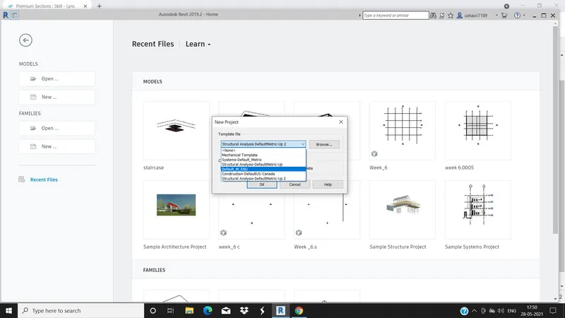
1.Open the Revit software and open the new and select Architectural template.
2.Select the grids in the Architectural tab and draw the reffenece grids .
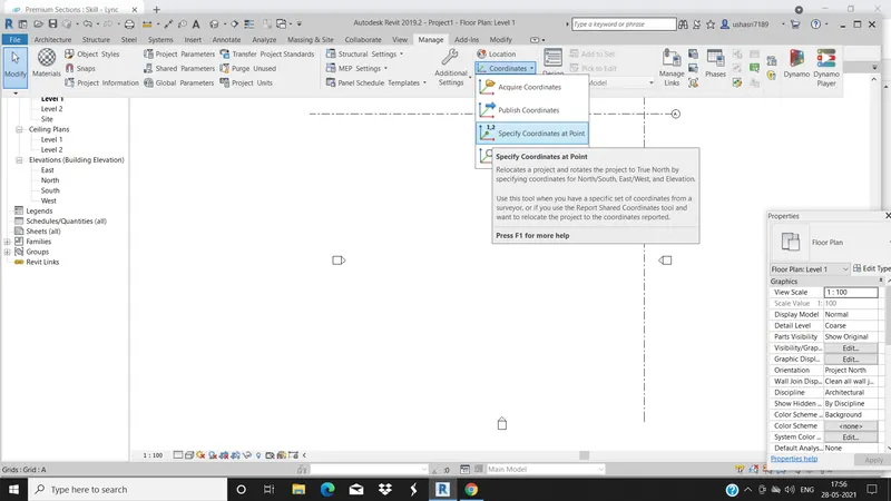
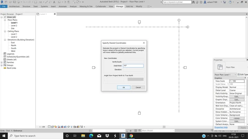
3. Select the manage tab and go the specify shared coordinates and make the new coordinates as 0'0" in both the direction.
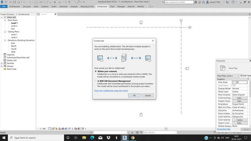
4.Select colobrate and select within your network and save the file as Architectural.
5. Open the Structural template and draw the grids with the help of grids icon under the Structural tab.
6. go to the manage tab and select the specfy shared coordinates and make them as 0'0" in the both north-south and east-west.
7.select the collobrate tab and click on collobrate and then click on within your network and click ok.
8. open the Architectural file and go to the manage tab and the click on manage links and add the structural file to it
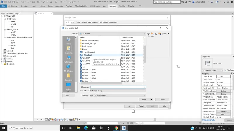
9.Now go to manage tab and click on acquire coordinates and then relocte the grids by selecting them,now both the grids get overlapped.
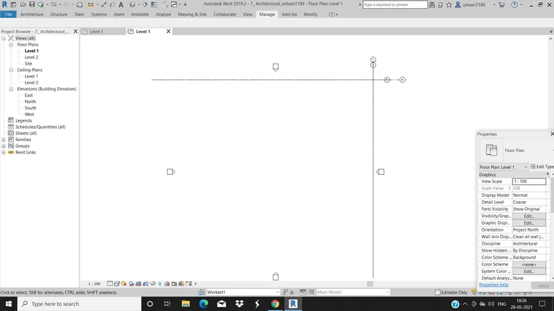
10. Now open the structural template and draw the grids at an internal in both horizantal and traverse directions.
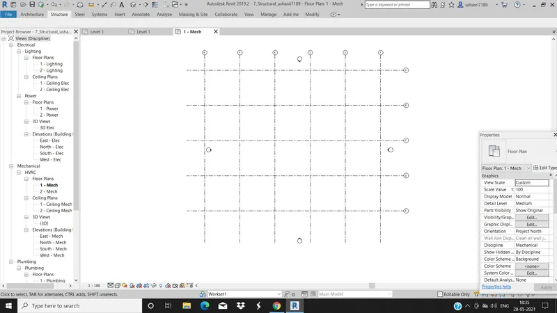
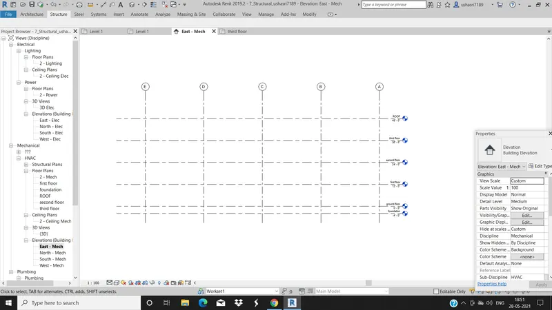
11.Now open the elevation view and mark the levels at an internal of 12' and rename them.
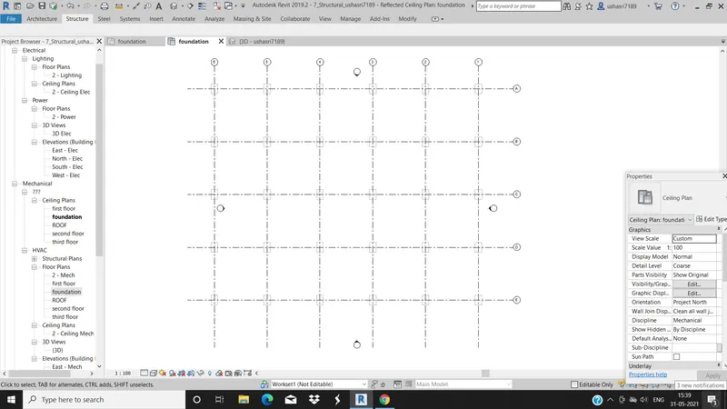
12.Go to Structural tab and select the column icon and select vertical column and size column you need to place from the properties browser and place the coulmn at the intersection of the grids.
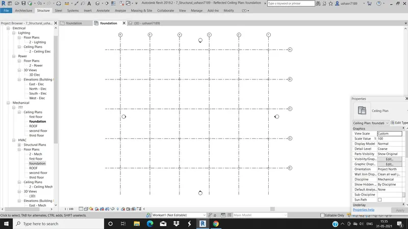
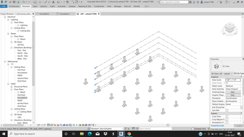
13.Select the foundation Isolated in the Structural tab and go the foundation plan and place the footing at intersection of the grids.
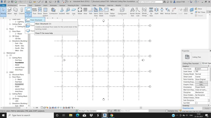
14.Go to the floor and then floor structural and pick the lines and click finish.
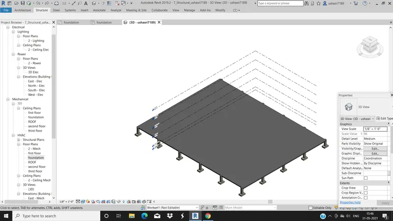
15. Select the beams in the structural tab and plaxe between the coloums.
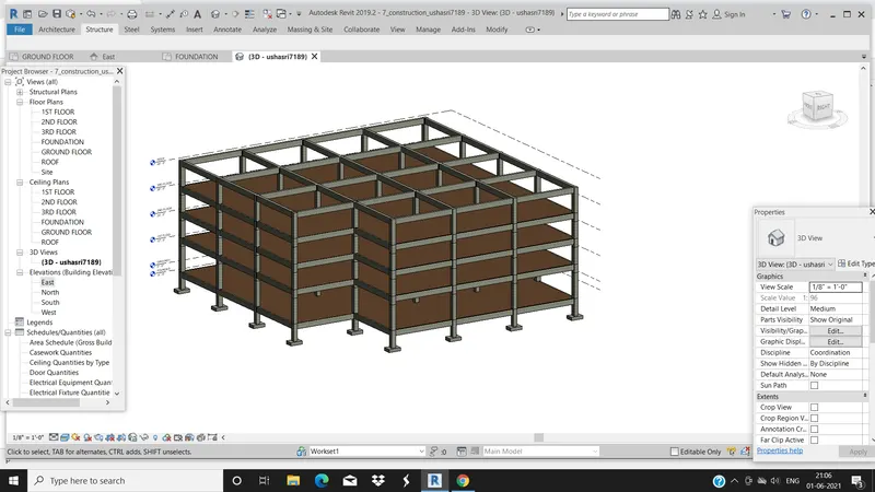
16.SELECT the beams in the structural tab and place them between the columns.
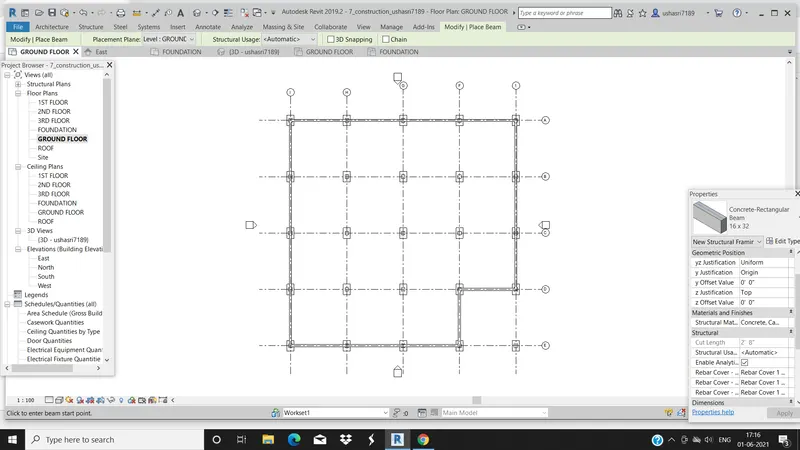
RESULT: The Structural template is created and the collobration is done and a;; the structural components like beams , floor, coloumns, footing are successfully placed.
4)
AIM:To include the components like walls, components, stairs, topographic components ect., to the Architectural model.
TOOLS USED:
- Architectural tab
- walls
- stairs
- curtain walls
- glasspanels
- lighting fixtures
- Railing
- windows
- Doors
- components like desk
PROCEDURE:
1. Open the Architectural template then draw the grids and levels and rename them.
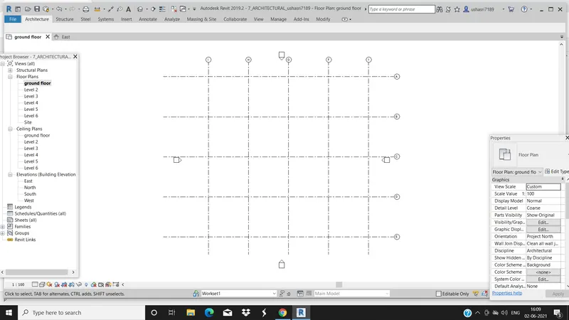
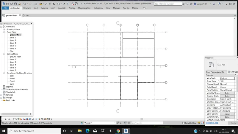
2. Draw the exterior and interior walls to the model and using the wall in the Architectural.
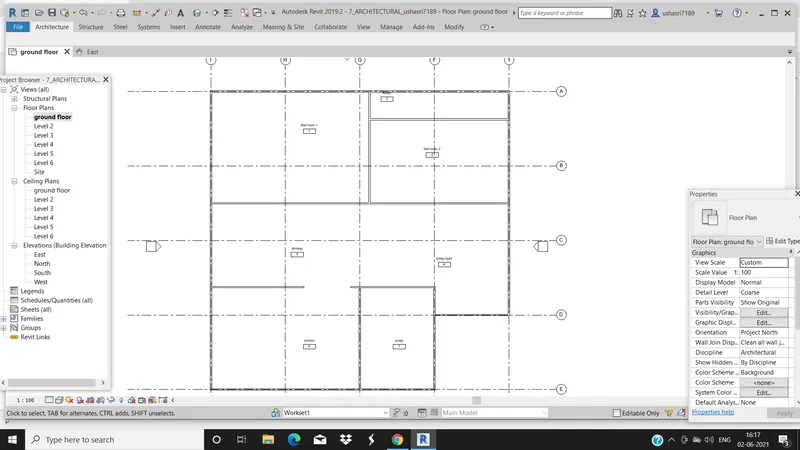
3. Now add the room tags and name the rooms.
4.Go to Architecture tab and add doors and windows.
5. go to architecture tab and select components ,then load family and add the beds, furnitures, sofa, tables, lights, ect,.
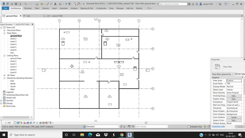
6. Add railings and staircase and also side walls around the stair care.
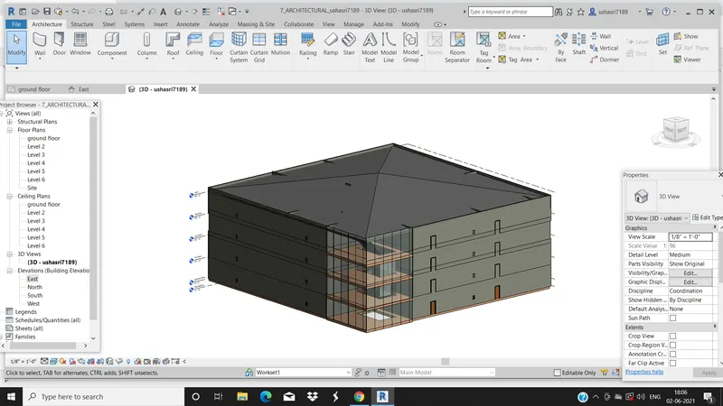
RESULT:All the components are placed in the Architectural model, the stirs and the lightings fixtures are loaded from families and placed successfully .The walls are placed and floors are drawn.
5)
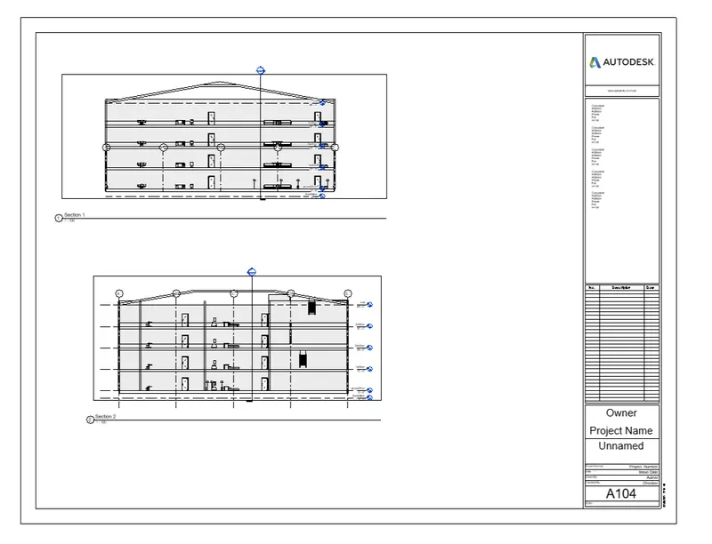
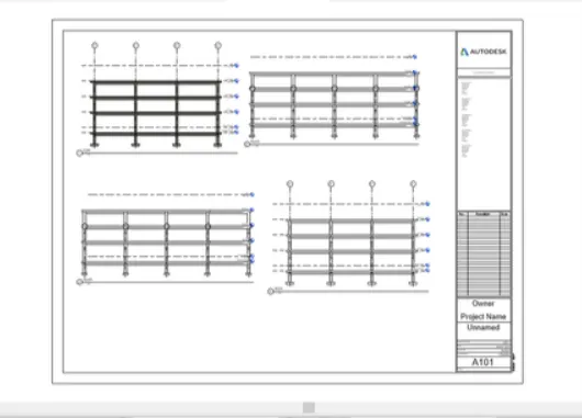
AIM: To provide the Drawing in the Architectural and Structural model with the floowing floor plan , elevation, section with categories and include appropriate sheet template.
TOOL USED:
- Insert
- sheets
- load families
- view
- section
PROCEDURE:
1. Open the Architectural template.
2.go to view on click on sheet and load the required size of sheet
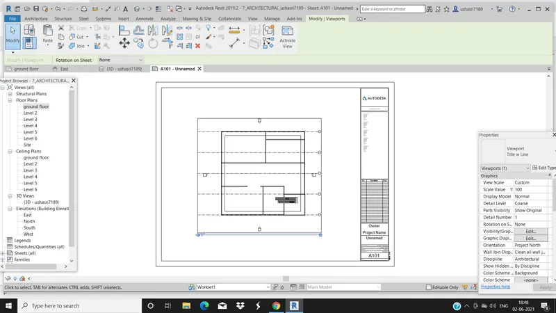
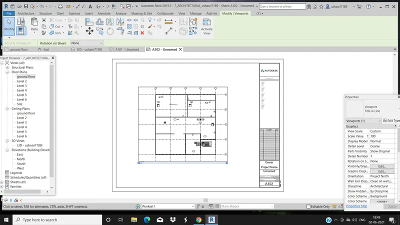
3. add the view like floor plans to the sheet in properties browser you can edit the sheet in properties browser you can edit the name of the sheet and the project name and other details.
STRUCTURAL VIEW OF SECOND FLOOR
ARCHITECTURAL VIEW
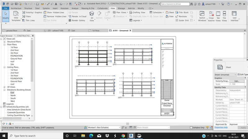
4. Go to view and select new sheet and add elevation views to the sheet and rename the sheet in the properties browsr . You can change the scale in the properties browser.
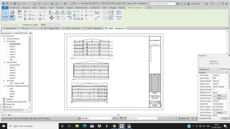
STRUCTURAL ELEVATION
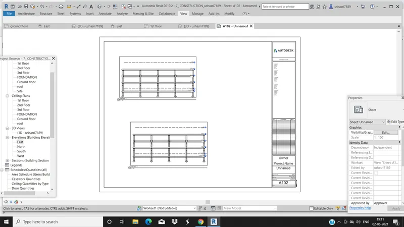
5. Go to view and click on sections and draw the sections in the direction of viw which we needed
STRUCTURAL SECTION VIEW
ARCHITECTURAL SECTION VIEW
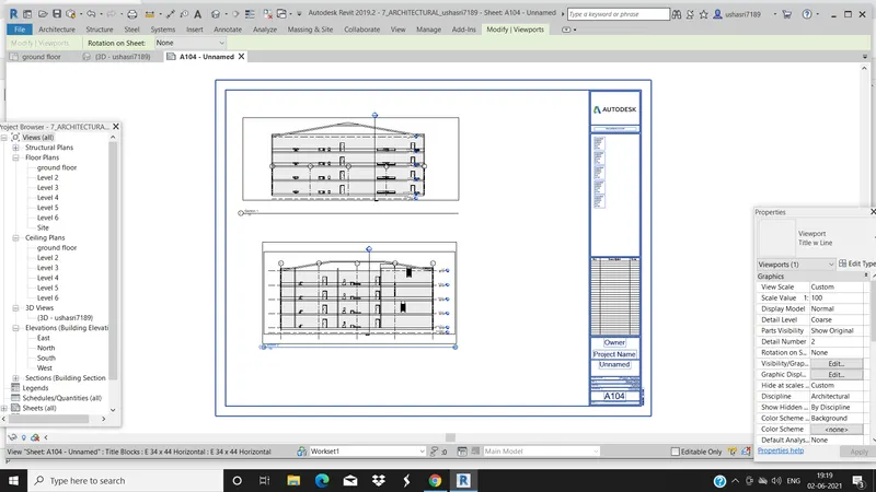
RESULT: The floor plan, section, elevation view, of the structural and Architectural model are placed in the sheet successfully by renaming the sheets.
6)
AIM: To render the images captured by camera in the interior rooms, from outside, structural framing in the 3D model and include ing the rendering images to the drawin sheets.
TOOLS USED:
- Render
- region
- style
- scheme
- view
PROCEDURE:
1. Open the Architectural model and go to view then click on remder you will find a dialouge box in that slect the region and select the region you need to render.
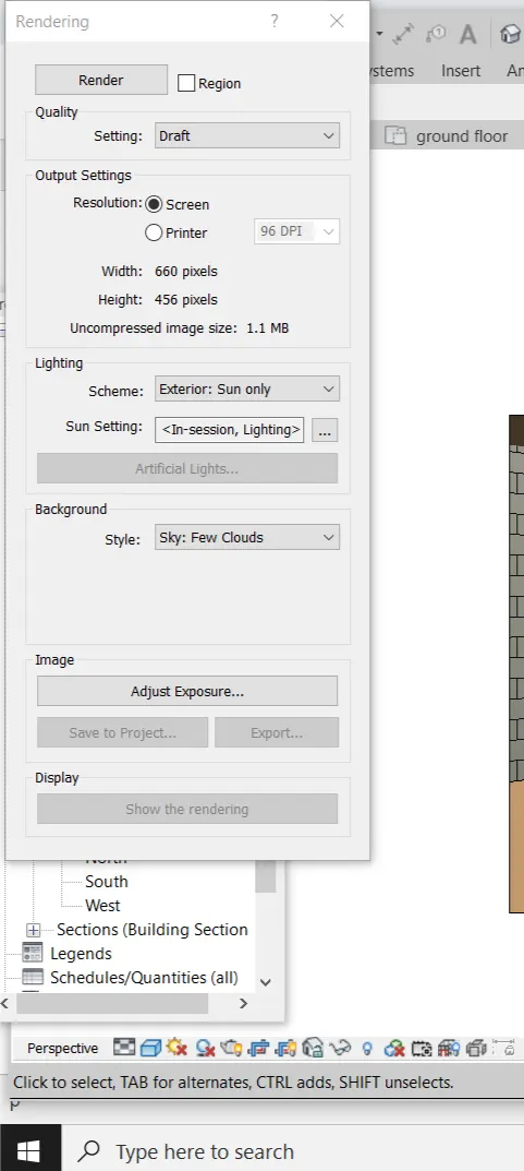
3. Under lightings in scheme youncam change the exterior and interior lightings, you can also change the background settings and click on render
4. Then click on saveed and we place the image in sheets.
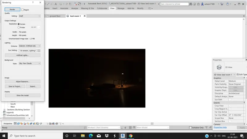
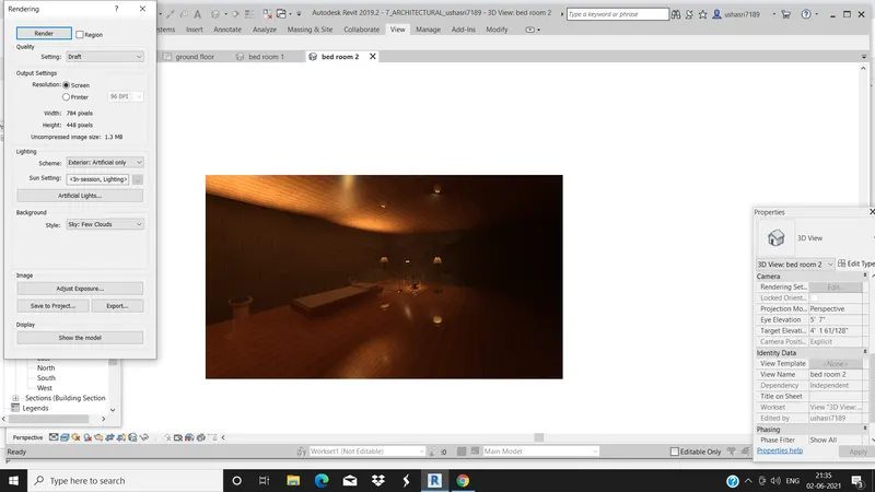
Below are the rendering images :
These rendering helps us to view the project in more realistic way
a) Rending from interior rooms
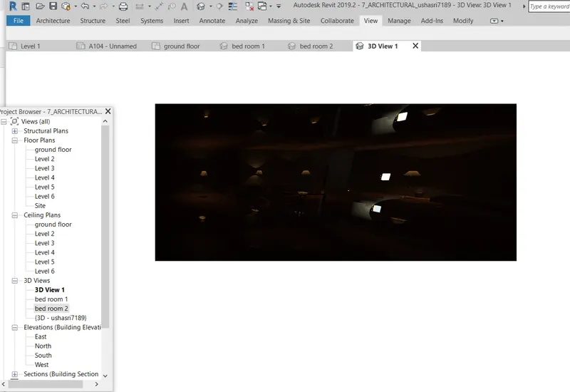
b. Rendering from out side topographic features
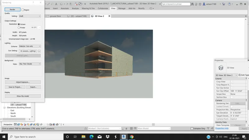
c. rendering through structural framing.
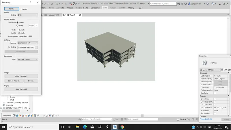
RESULT:By using the rendering setting the images of the interior of building and topographic features of the model and structural images are rendering successfully
7)
AIM: To print the set of drawing sheets crested and submitting the drawings from architecture and structural model.
TOOLS USED:
- file
- setup page
PROCEDURE:
1.SELECT the view and go to file menu and click on print .
2. A dialouge box appers.
3. we need to change the settings on how we need to be printed and click on print option .
RESULT:
I dont have printer right now so iam unable to to print the sheets so iam attaching the screenshorts of the sheets how they look like when we print them.