Creating an Architectural plan for the provided plot size and develop relevant basic structural drawings
CREATING AN ARCHITECTURAL PLAN FOR THE PROVIDED PLOT SIZE AND DEVELOP RELEVANT BASIC STRUCTURAL DRAWINGS
Aim:
To design and draft a layout of a residential building within a plot size of 60'x20', facing east. This must include:
1. Architectural Drawing (floor plan, elevations and section)
2. Structural drawing (column, beam, footing plan)
Introduction:
To develop an architectural plan and structural plan various commands used include:
- Xline or construction line: This is used to draw infinite lines which are very much essential in developing sections and elevation.
- Line: Used to draw different entities like walls windows etc.
- Offset: This is also used extensively to develop walls; for external walls an offset of 0.23m and internal walls 0.15m is taken.
- Trim: This tool is used to remove or erase the unwanted lines.
- Extend: It is used to extend a line.
- Copy: Command used is C. This tool is used to copy an entity especially while drawing a plan where you can copy the ground floor plan to develop the first floor plan.
- Mirror: Command: MI. This tool is used to mirror/ flip an object.
- Hatch: this tool is used to provide the appropriate hatching to different portions like brick walls, concrete lintels.
- Fillet: This tool is very much essential in developing corners where the radius can be provided as 0.
- Layers: This enables us to assign different properties to different entities in a very easy way.
Procedure:
- Initially set the units of the drawing as decimal (meters).
- Now, set the limits of the drawingg:
- Specify the lower left corner: (0,0)
- Specify the upper right corner: (1000,1000)

Architectural drawing: Plan, Section and Elevation
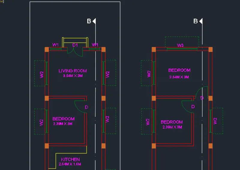
- Now, using the line option, the given plot area is drafted i.e, 18.3m x 6m.
- So, after deductions the plan area is taken as 14.3m x 4m.

- Now, using the rec command draw rectangle of size 14.3m x 4m.
- Offset this rectangle at an offset distance of 0.23m inwards to represent external walls; the internal wall thickness is taken as 0.15m.
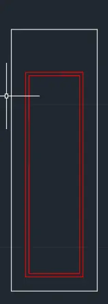
- Now, using the line and offset command complete the plan of the ground floor.
- Doors and windows are also created using line, circle and offset tools.
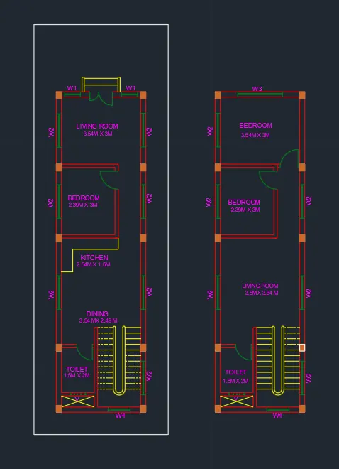
- Dimensions of doors, D=0.8mx2.1m; D1=1mx2.1m (Double door)
- Dimensions of windows, W1=0.7mx1.6m; W2= 1.5mx1.2m; W3= 2mx1.5m; W4= 1mx1.2m.
- Dimension of ventilation, V= 0.7mx0.6m.
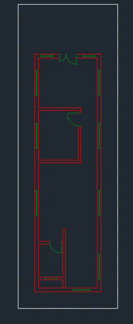
- Staircase is drawn with riser of 0.15m and tread of 0.25m.
- Kitchen slab is drawn (width= 0.5m)
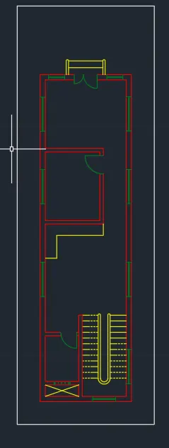
- Now, inorder to draw the 1 st floor, copy this drawing next to it and make necessary changes.
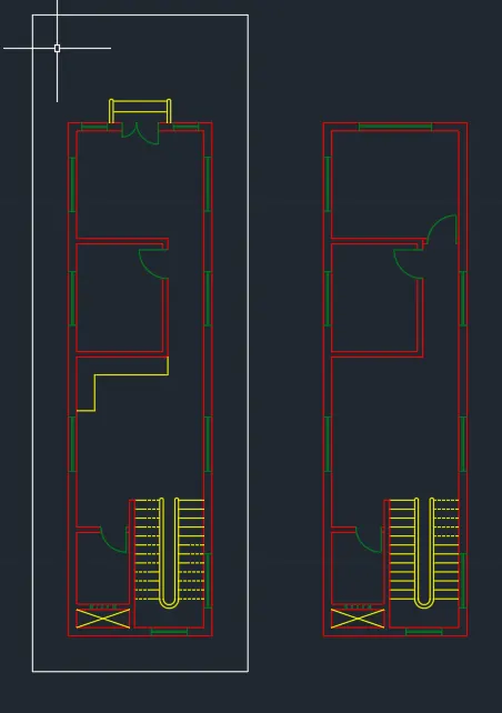
- Now, provide columns wherever necessary.
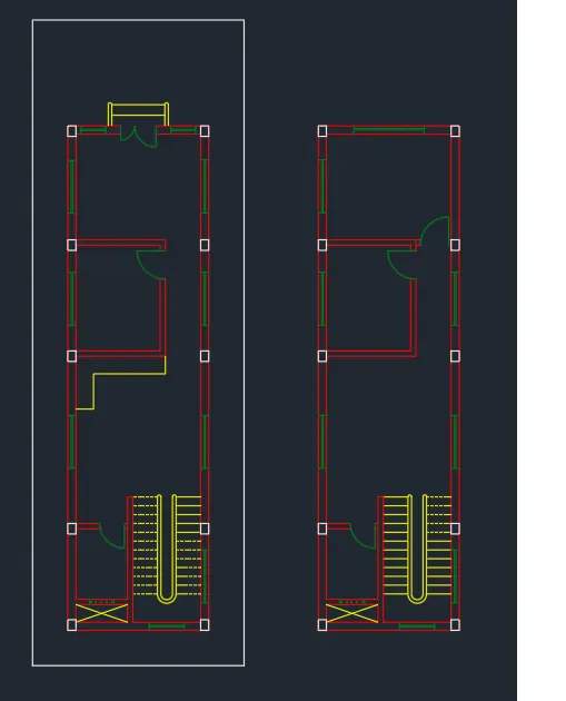
- Column hatching is provided.
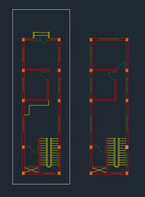
- Now, inorder to complete the plan texts and dimensions are included.
- Now, the section to be cut is also added to the plan.
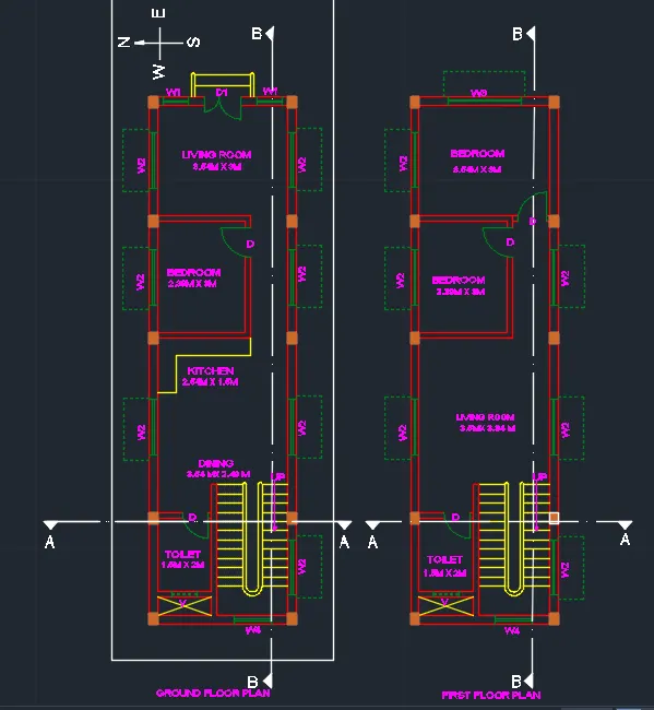

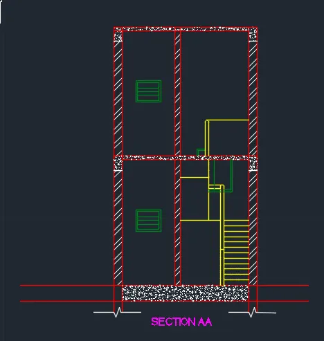
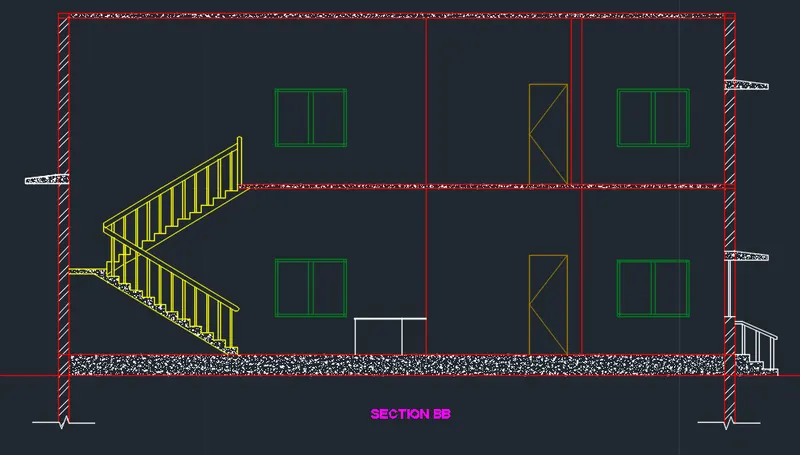
- Now, the two sections i.e section AA and section BB are drawn using the AutoCAD tools line, offset, copy, mirror, trim etc.
- Section AA
- Section BB
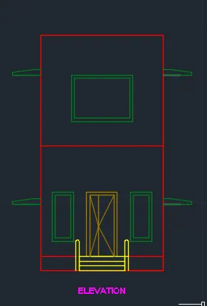
- Elevation : This is drawn by simply projecting the plan to obtain the front elevation(east).
Structural drawing: Column, Beam and Footing plan.
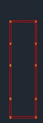
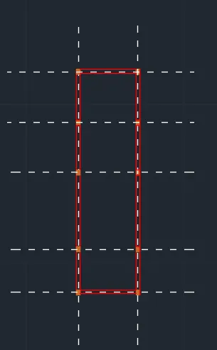
1. Column drawing
- Inorder to obtain the column drawing, initiallty copy the groung floor plan and then only retain the column portion of the plan.
- After this, draw the centreline for walls and columns.
- Hence, the obtained drawing is the column drawing.
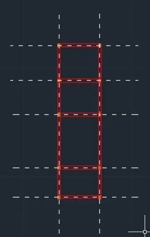
2. Beam drawing:
- To obtain this, draw beams wherever the walls are present using the line command.
3. Footing plan:
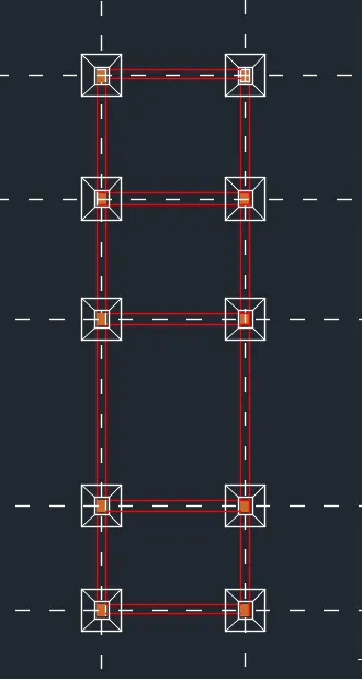
- For this draw draw two rectangles around the columns, one slightly bigger than the column dimensions and the other bigger one inroder to create a slopped footing for the column as shown below:
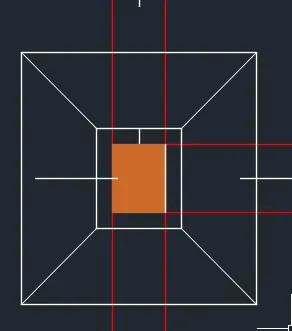
- Simlilarly complete it for all the columns. Hence, the final structural drawing obtained is given below:
Result:
Layout of a residential building is drafted as shown below:
1. Architectural drawing:
Plan:
Sections:
Section AA
Section BB
East facing Elevation:
2. Structural Drawing:
Column drawing:
Beam drawing:
Combined structural drawing: consisting of column, beam and footing plan.