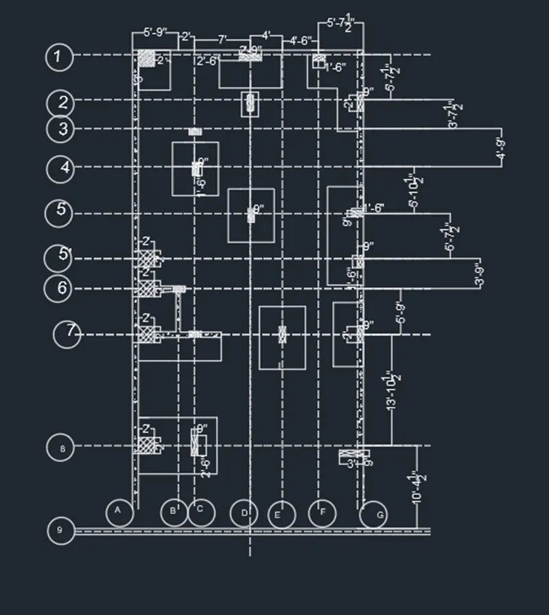
Creating a Wardrobe detailed drawing, Floor Plan, Kitchen Layout and Column Detail using AutoCad
1)
Aim - To draw the cabinet,floor plan,kitchen,column details and rafe layout of the giving drawings
Sketching Plan -
Procedure -
- Open AutoCad
- Take n new drawing by QNEW and select decimal
- Set the units
- Set the LIMITS,lower limit as 0.0 and upper limit as 1000,1000
- Type Z enter and A enter for zoom all
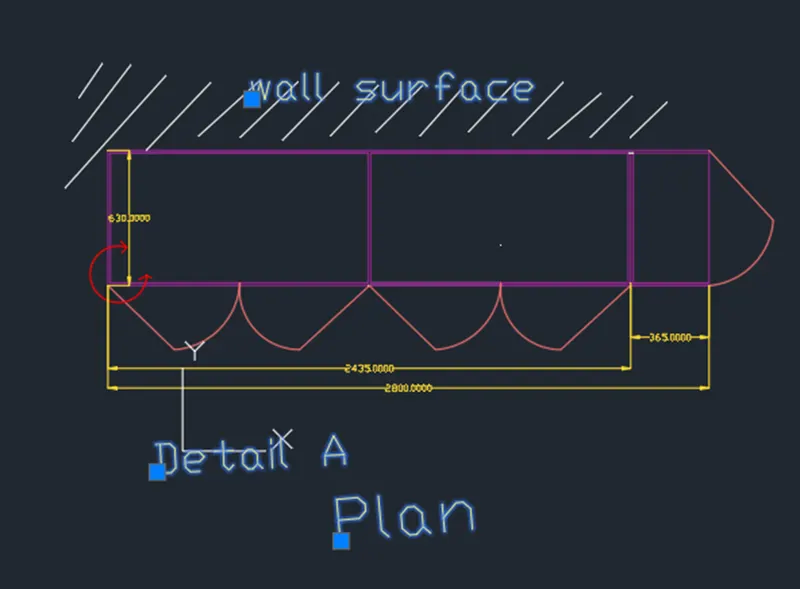
- Using RECTANGULAR command ,draw a rectangle of size 2800x630mm
- Using OFFSET command ,offset of 12mm inside is made to represent the thickness.
- Explode the rectangle using the EXPLODE command
- Using OFFSET command ,take offset from the right side of rectangle for a distance of 365mmand also to two sides of 365mm by 12mm
- Take offset of 365mm at a distance of 1217.5mm,i.e,at the mid of 2435mm, and now take the offset of 12mm to the left using OFFSET command.
- From 1217.5mm,draw a line to centre on both sides by OFFSET command,giving offset distance 608.75
- Trim the lines such that the line at bottom portion only exist,now using OFFSET command,offset of 4mm is made on both sides and delete the centre line on both the door portion
- Now using LINE command and ARC,draw the door.

Result -
Sketching Front Elevation -
Procedure -
- Project the lines from both the ends of the plan view and take 12mm line on left side with ORTHO ON
- Using XLINE draw horizontal line as bottom and take offset using OFFSET command of 2600mm from horizontal line
- From the bottom line ,draw an offset of 100mm using OFFSET command
- Now using OFFSET command ,from the bottom line take another offset of 2100mm to top and 12mm thickness from top
- Now project the line of 365mm and 1217.5mm from plan to elevation,by EXTEND or LINE tool
- Now project the doors from the plan using EXTEND command
- Now using TRIM command ,trim off the unwanted line
- Using LINE command,draw the crossing lines by line tool to indicate the doors
- Now using LINE command ,draw the handles with 80mm width and 995mm height
- Now draw the locking section using the CIRCLE tool
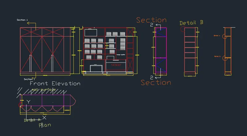
- Now make a 1-1 section line.
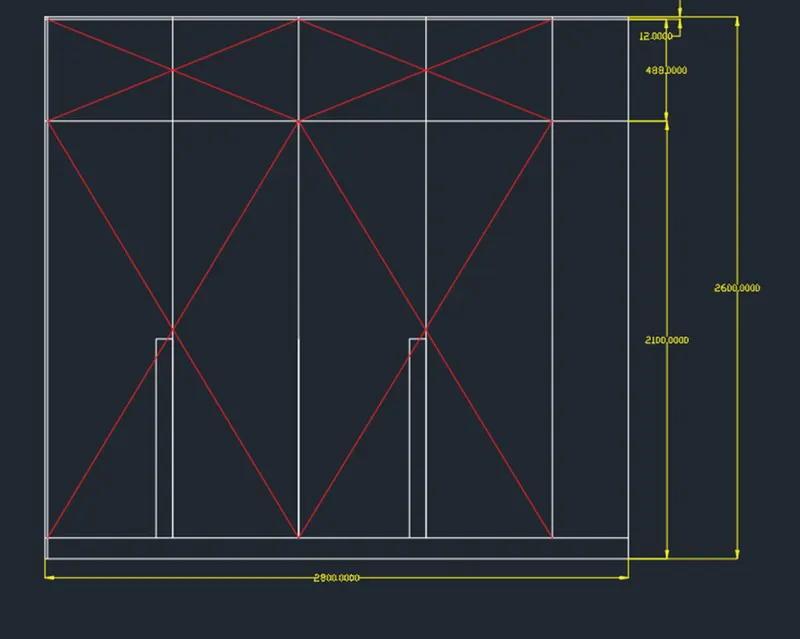
Result -
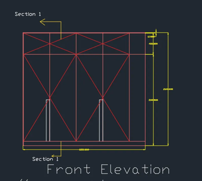
Sketching Carcase Elevation
Procedure -
- Project the lines to side from elevation to botom line
- Using OFFSET command,offset 100mm line,2100mm line from bottom and 12mm thickness with ORTHO ON
- Now project the ends of cabinet from the plan view
- Using OFFSET command,offset distance of 20mm (720-680=40 , 40/2 = 20)from the bottom horizontal line from 100mm offsetted line ,set vertical line and top line from 12mm offsetted line.
- Using OFFSET command, offset of 1223mm from left end and 12mm line using OFFSET command
- Using FILLET command ,fillet the corners of cabinet
- Using OFFSET command,offset line at a distance of 680mm from the bottom 20mm offsetted line ,then again offset 20mm from that line ,to create inside partition.
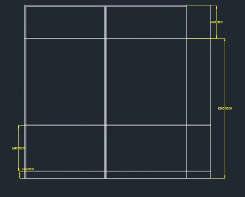
- Now create offset of 300mm and 20mm as thicknessbtill it meets the height of 2100mm using OFFSET command
- Now,using DIVIDE command ,dividing the second portion of cabinet into half to create hanger space
- Using OFFSET command,offset distance as 580mm and thickness as 20mm is made
- Now trim off unwanted line in the hanger space using TRIM command
- Using DIVIDE command,divide the 1st shelf of 300mm from bottom left side in middle of it
- Using OFFSET command,offset 100mm from the two sides and bottom,to create drawer in right side.
- using OFFSET command,offset distance of 500mm from bottom line is made
- using OFFSET command,draw a line from the bottom as offset of 900mm and 500mm from top ,right side
- Now draw the legs of cabinet by creating rectangle of 100x50mm using RECTANGLE command
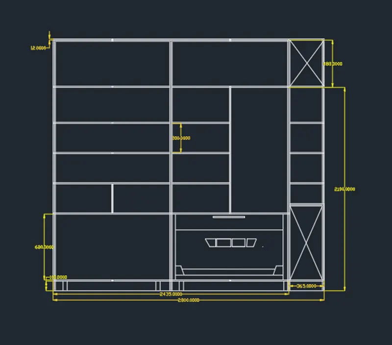
Result -
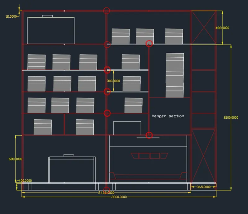
Sketching of Side Elevation
Procedure -
- Project the height from carcase elevation
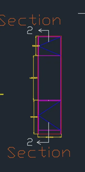
- Using LINE command,draw a line on left side and using OFFSET command ,offset 630mm from the right side
- Using OFFSET command,offset of 20mm is made to show the thickness on top and the sides
- Using OFFSET command,offset from bottom as 100mm,900mm,20mm thickness and 1180mm are made.
- Now made the section 2-2 line
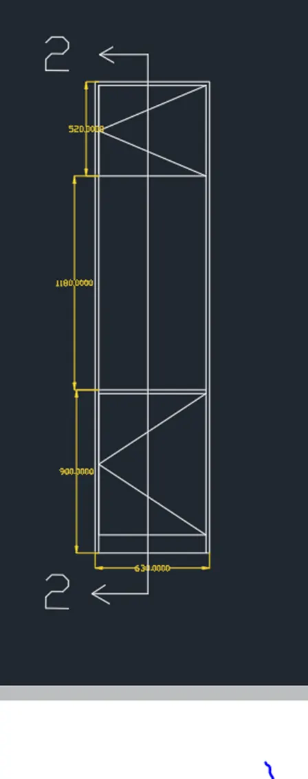
Result -
Sketching section 1-1
Procedure -
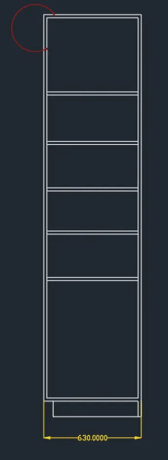
- section 1-1 in elevation ,so we need to project the height from the elevation
- Using OFFSET command,offset of 630mm,which is the width is made
- using OFFSET command,provide an offset of 20mm for thickness
- For the inside cabinet,project line from the carcase elevationof 100mm,900mm,300mm and 20mm as thickness
- Nowtrim off unwanted line using TRIM command
Result -
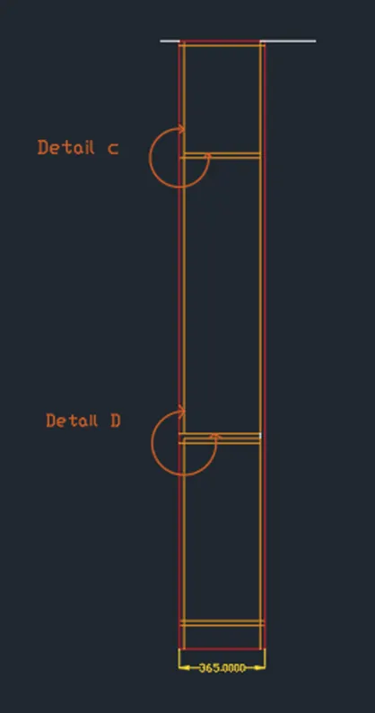
Sketching Section 2-2
Procedure -
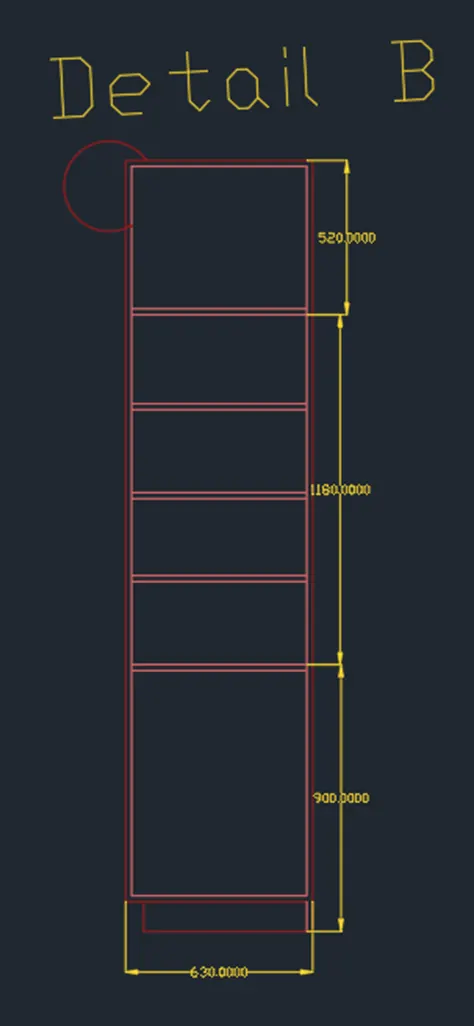
- Project the height from side elevation as the section is from the inside elevation
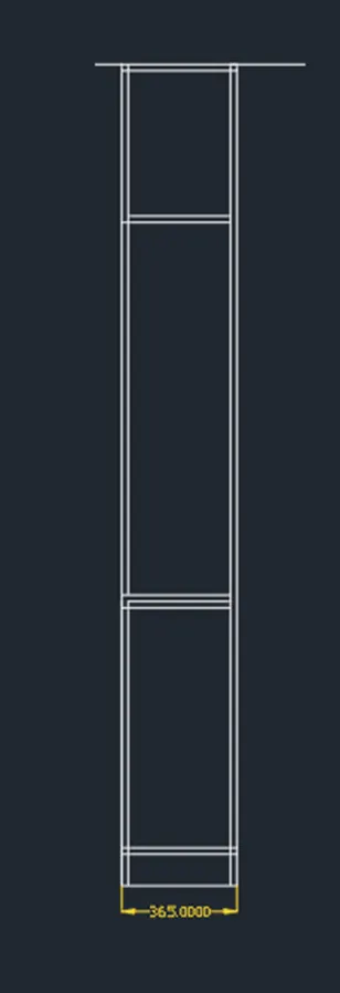
- Using OFFSET command,offset of 365mm is made as width
- Using OFFSET command,offset on the sides and top of 20mm
- Project the 900mm line from the bottom and 520mm line from top
Result -
Final Drawing -
2)
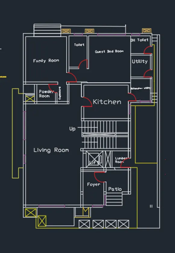
Aim - To draw the floor plan of the given building
Procedure -
- using XLINE command draw a horizontal line and vertical line
- using OFFSET command, give an offset of 230mm from the vertical line to draw the wall thickness
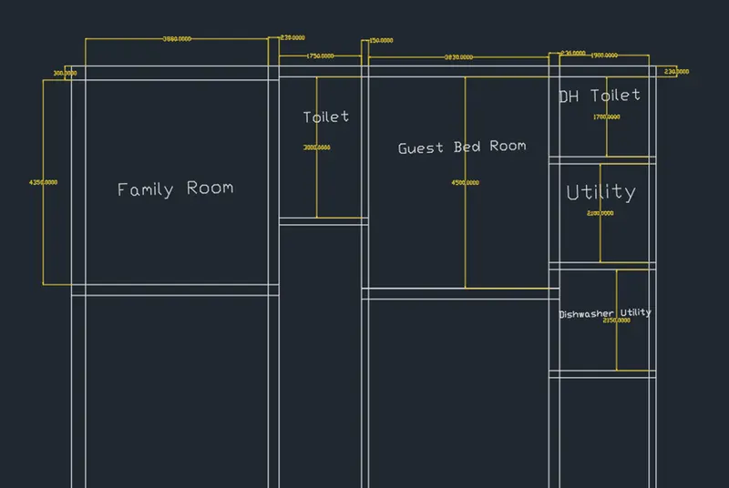
- Sketching Family Room - Using OFFSET command,give an offset of 3880mm from wall thickness and offset 230mm for other side.using the offset command ,draw an offset of 300mm as wall thickness from horizontal line.Draw another offset of 4350mm from the 300mm wall thickness for drawing the family room.
- Sketching Toilet - using OFFSET command,give an offset of 1750mm from the right wall of family room,also offset of 150mm is made to show the wall thickness.using OFFSET command,draw an offset of 250mm from the horizontal construction line for wall thickness of toilet on outside.Now draw an offset 300mm from the wall thickness ,so that the toilet is sketched.from the offsetted line,draw 150mm for wall thickness inside.
- Sketching Guest Bed Room - using OFFSET command,draw an offset from the wall of toilet asat a distance of 3830mm.Also offset the wall thickness of 230mm.now using OFFSET command,offset 4500mm from horizontal wall and also offset 230mm from that line
- Sketching DH toilet - Using OFFSET command,Take offset from guest bed room wall of distance 1900mm towards right side.Also offset the wall thickness 150mm from that line.Now offset a distence of 1700mm from horizontal line,wall thickness 230mm.also offset a wall thickness 150mm now using TRIM command ,trin off unwanted line of horizontal construction line
- Sketching of Utility Room - Using OFFSET command,take an offset of 2100mm downward the wall of DH toilet.also offset the wall thickness of 150mm
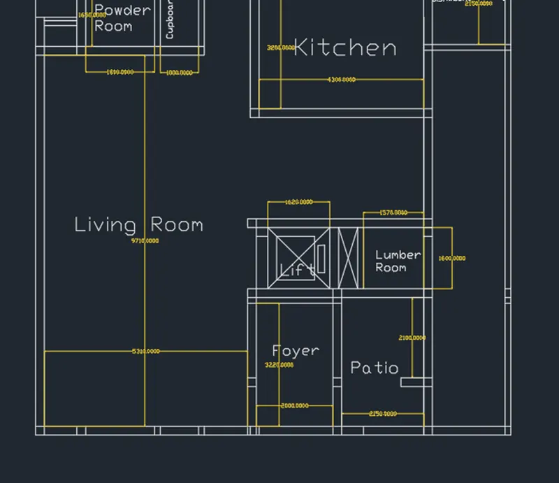
- Sketching of Dishwasher utility -From utility wall,take an offset of 2150mm downward and also wall thickness 150mm
- Sketching Kitchen - From left all of dishwasher utility room,take an offset of 4300mm to the left and wall thickness of 230mm.from the wall of guest bed room ,take an offset of 3200mm downward and also wall thickness of 230mm.Now extend the top wall of kitchen upto a distance of 1462mm excluding wall thickness
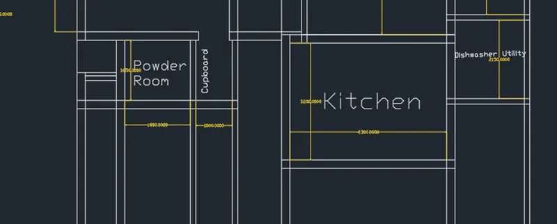
- Sketching Foyer - using OFFSET command,draw offset from wall of living room 2000mm to the right and wall thickness of 230mm.Draw the width of room 3220mm offsetting from line extended from living room.Now offset the wall thickness of 150mm.againg offset 230mm from lift room and extend it to right end
- Sketching Patio - From the wall thickness of 230mm draw an offset of 2100mm downward.from the wall of foyer draw an offset of 2150mm and wall thickness of 150mm to right side
- Sketching lumber Room - From the wall of patio,draw an offset of 1600mm towards backside.offset a wall thickness of 230mm.to the left side,give an offset of 150mm as wall thickness.
- Sketching Duct and Lift - Using OFFSET command,draw an offset of 500mm from 150mm wall of lumber room and wall thickness 230mm.Now take an offset of 1620mm from wall for lift.Draw side wall and front wall of 230mm.
- Sketching Stairs - Thread 300mm and rise 150mm.divide the stair room and offset 200mm to two sides by the offset from centre line.Now draw the first stpe,then offset 300mm upto 11 divisions,and the rest of portion forms the landing,draw 10 threads from landing on other side of division.
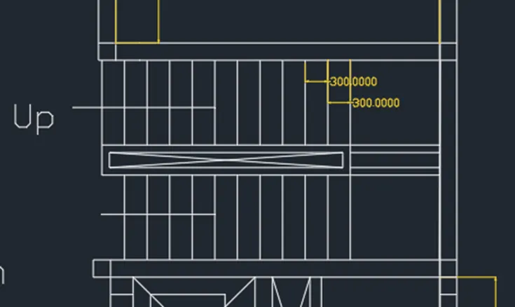
- Sketching Outside Ducts and Steps - Create duct at front and backside.steps on back with thread 350mm and side 250mm
- Opening for doors,Draw doors and windows - Opening are given by TRIM command,where ever door is required.for D1=1000mm , D2=900mm , D3=800mm , D4=750mm , D5=700mmmm is trimmed accordingly
- By creating hinge and with CIRCLE command,circle with points with midpoint of hinge are drawn.Vertical line showing the shutter is shown and rest of circle is trimmed off
- Craete window of size W1=2700mm, W2=2500mm, W3=900mm, w5=1000mm, W9=800mm, V1=800mm, V2=750mm
- Now fillet the corners using FILLET command and trim off the unwanted line using TRIM command
Final Drawing -
3)
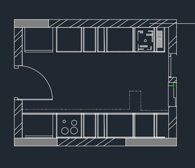
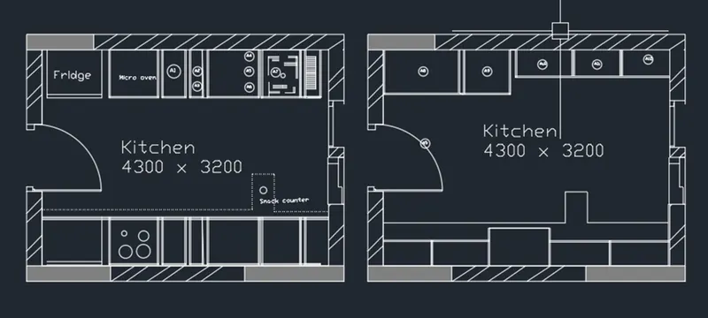
Aim - to create the kitchen layout
Procedure -
Step 1 - Units are set to mm
- limits and limmax are also set
- zoom command is also used
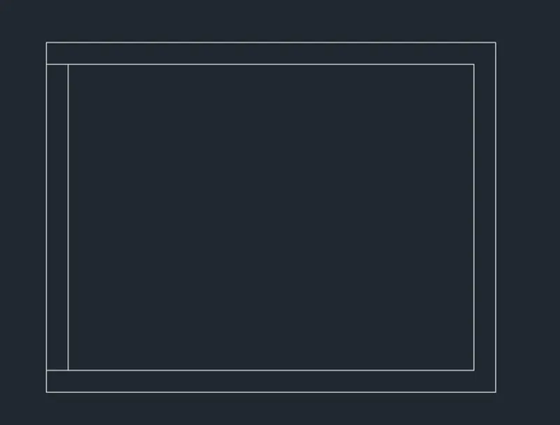
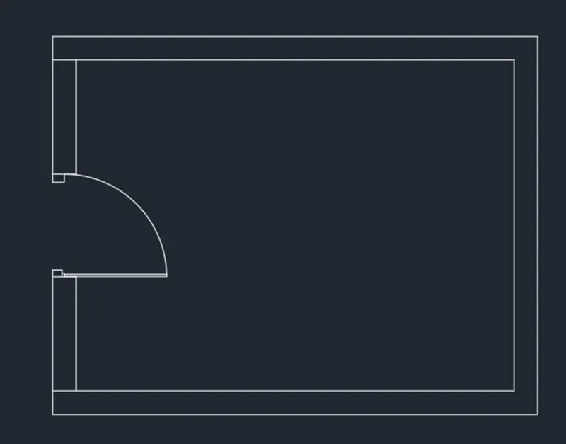
Step 2 - In the command prompt tyoe REC and the dimensions are 4734 x 3688mm
- In the command prompt type offset and offset it to the distance of 230mm
- Using arc and lines the door is drawn
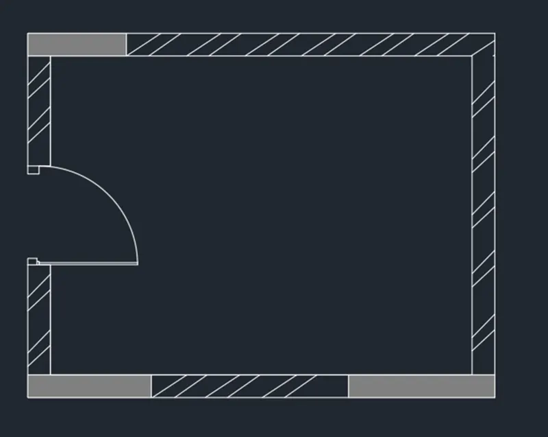
- In the command prompt type hatch to hatch the model
- In the command prompt type rec> dimensions,to do the fridge
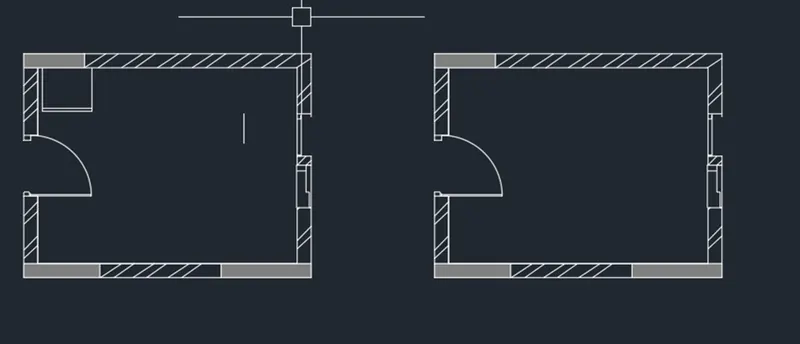
- In the command prompt type offset and offset to desired distance to get Micro Oven
- In the command type trim to trim the extra line
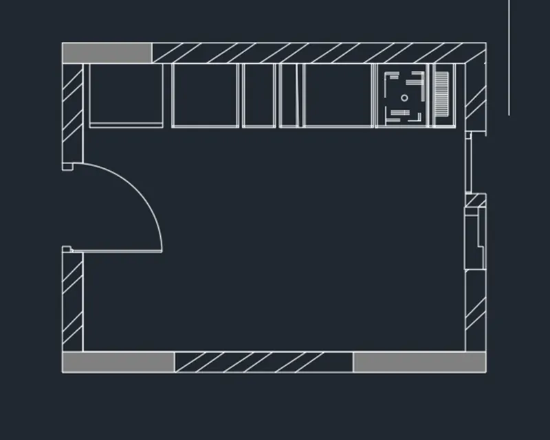
- In the command type offset and offset to the horizontal distance of 350,450,900,450,and 560
- In the command type offset and offset it to vertical distance of 600
- in the command type trim to trim the extra line
- In the command type line type and load the dotted lines
- In the command type text to text the given annotataion
- In the command type dimensions are given to plan
- In the command even the leader command is used to name the dimensions
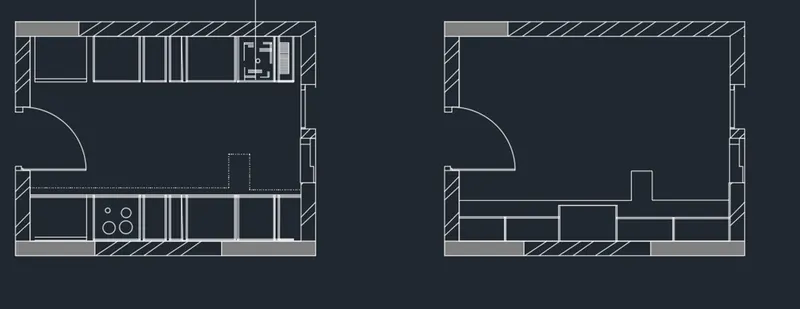
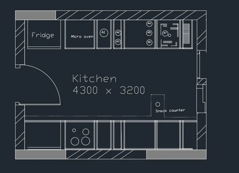
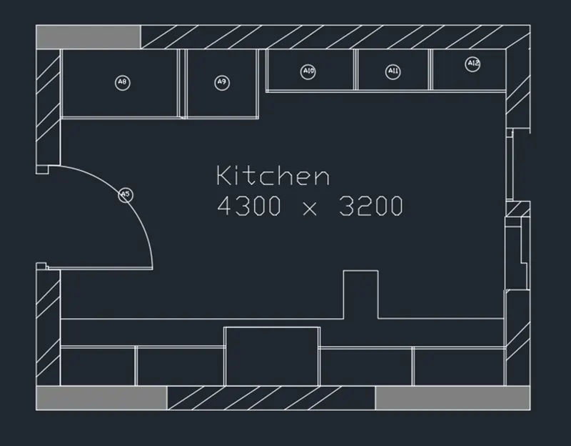
Final Drawing -
4)
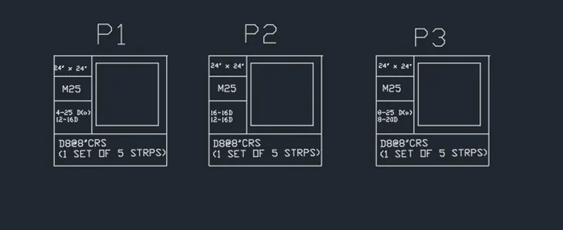
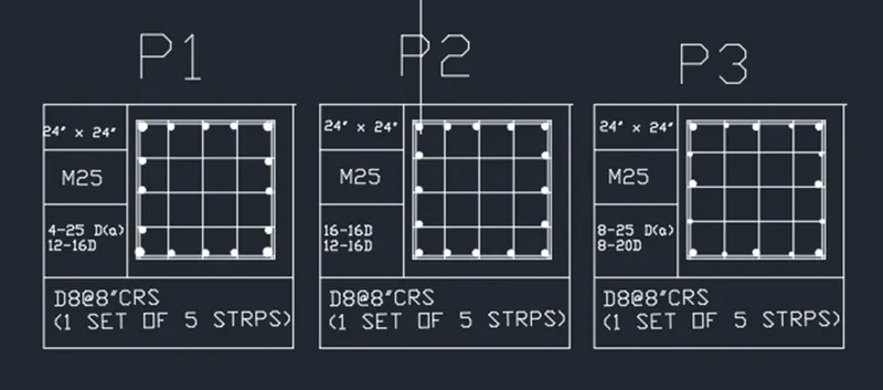
Aim - To sketch the column details
Insert dimensions and text in the figure and refer bar size from schedule
8mm --0.31
25mm --1 inches
16mm - 0.62 inches
Procedure -
Step 1 - Units are set to mm
- limits and limax are aslo set
- zoom command is also used
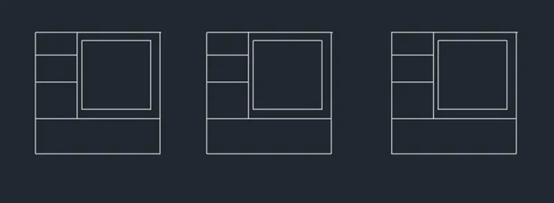
Step 2 - Using rectangle and line command the table are drawn
Step 3 - using text command the text are given
Step 4 - In the command type line to draw the reinforcement
- in the command type circle to draw the reinforcement
Final Drawing -
5)
Aim - To draw Raft Layout
Procedure -
Step 1 - Units are set to Engineering and inches
- limits and limax are also set
- zoom command is also used
Step 2 - In the command type rectangle and the dimensions are 29'7" and 60'
- To get dotted line click on line type and load the dotted line current
- With the help of dotted line and offset command the grid are drawn
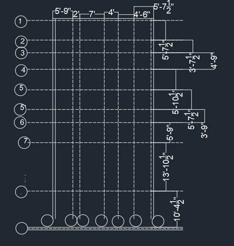
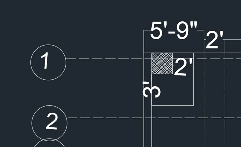
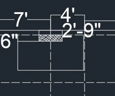
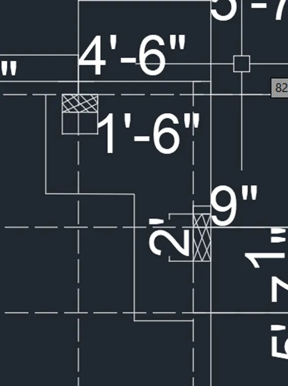
Step 3 - In the command,type rec 2'x2'
- In the ribbon bar select hatch ANS137
- In the command type rec tp draft the column
- In the ribbon tab >Annotation>text>Mtext to text the given annotation
- In the ribbon tab>Dimension>To give the dimensions
Final Drawing -