Creating a Wardrobe detailed drawing, Floor Plan, Kitchen Layout and Column Detail using AutoCad
- Draw the elevation and details of a wardrobe as shown in the Figure below. After sketching, you need to provide the dimensions and text with the use of layers. Use proper text styles and dimension methods to document it. Also, assume dimensions, wherever needed.
Note: All dimensions are in mm.
Ans.
AIM: To Draw the elevation and details of a wardrobe as shown in the Figure below. After sketching and to provide the dimensions and text with the use of layers
PROCEDURE
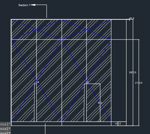
Step 1 Commands used are line, trim, zoom ,offset and erase
Line 2800 mm drawn and offset of 2100 mm taken

Step 2 Again Offset from the top of dimensions 12 mm and 488 mm

Step 3 the offset from the side at the distance of 608.75 and 365
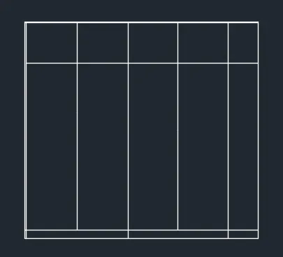
Step 4 the command line L and by increasing the transparency to create wall surface and door is shown with blue layer
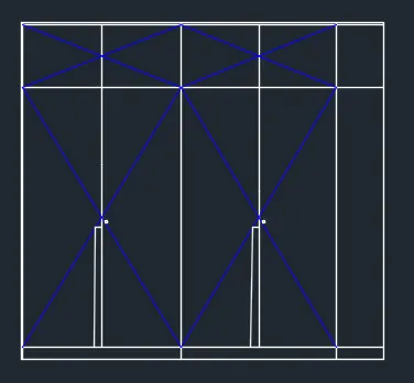
Step 5 by using hatch give the hatch and give scale 25
And dimension command is used for final drawing
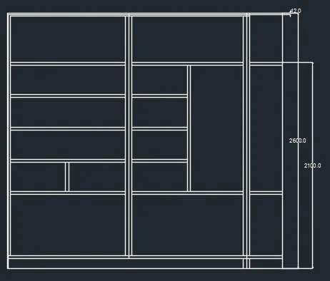
Step 6 For carcase elevation
Line command and offset is used
the command line type q leader to mention the annotation
the command prompt type rectangle 630 x2800
the command prompt type q leader to give the annotation
With the help of line command drawers and cabinets are created
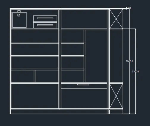
Step 7 command prompt type rectangle and dimensions of 520 x 630, 1180 x 630
using line commands, the next of the lines are drawn
Step 8
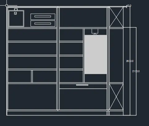
Step 9 For the drawers and cabinets give the grey colour
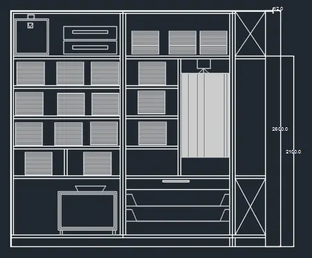
Step 10 Command dimensional is used to show the dimension of drawing
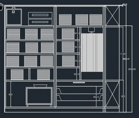
Step 11
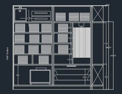
Step 12 For Plan view rectangle @ 2800 and 630 mm is drawn
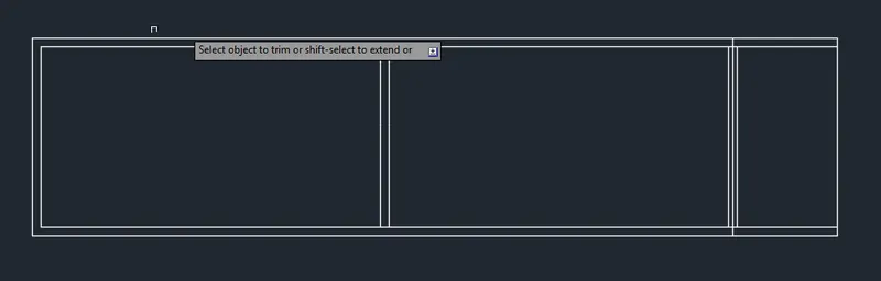
Step 13
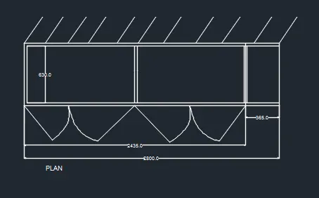
Step 14 For section line , offset
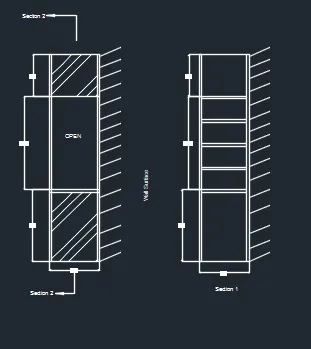
Step 15
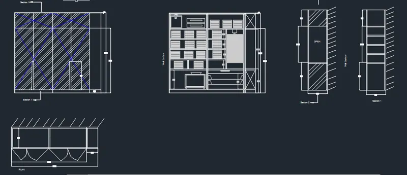
Q.2
Answer
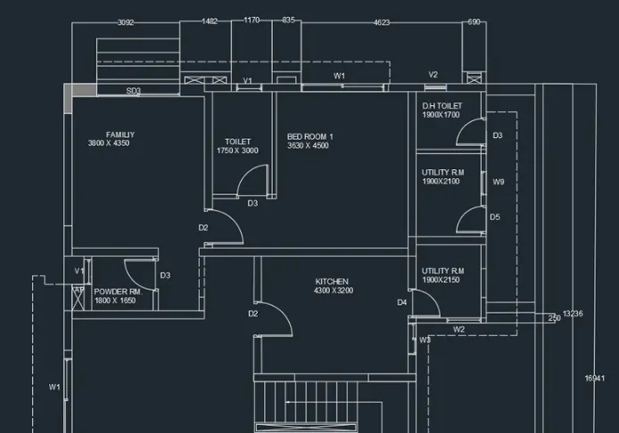
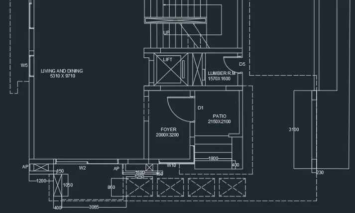
AIM : To draw the floor plan
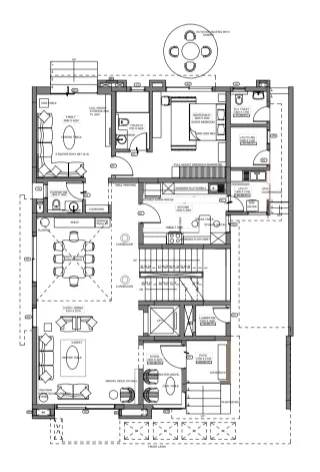
Procedure
Step 1
Units are set to mm
Limits and lim-max are also set
Zoom command is also used
Step 2
In the command prompt type XL to draw the infinite lines
In the command prompt type offset to offset the line for a particular distance
Using arc command doors are also created
Door Size used are
D1 - 1000 x 2000 mm, D2 - 900 x 2100 mm, D3 - 800 x 2100 mm, D4 - 750 x 2100 mm,D5 - 700 x 2100 mm,SD - 2256 X2100 mm
Window size are
2700 x 1500 mm , W2 - 2500 x 1500 mm, W3 - 900x 1500 mm,W5 - 1000 x 1500 mm,W9 - 800 x 1500 mm
Ventilator size are as V1- 800 x 500 mm , V2 - 750 x 500 mm
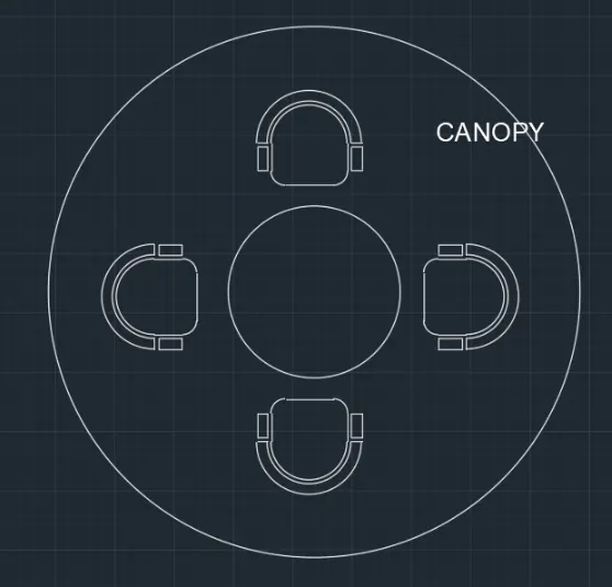
Now to draw canopy
In the menu bar click on circle
specify the centre point as 10,10 and radius 452
In the meu bar click on circle > centre, radius
specify the centre point same as the previous circle (10,10) and radius 1398
In the menu bar click on rectangular or In the command prompt type rectangle
specify the length of the rectangle as 662.3
specify the width of the rectangle as 298
In the command prompt type FILLET
Give the dimensions and anotation the drawing with the text where ever required
RESULT
Q.3
Ans
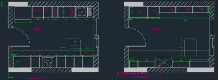
AIM To Create the Kitchen Layout and to Also, use proper dimension techniques to dimension the kitchen layout. Also, insert text wherever required
Procedure:
Step 1
Units are set to mm
Limits and lim-max are also set
Zoom command is also used
Step 2
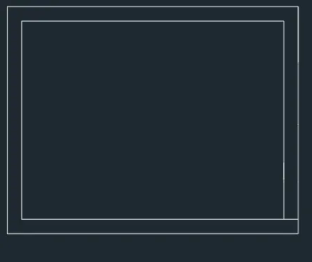
In the command prompt type rec and the dimensions are 4734 x 3688 mm
In the command prompt type offset and offset it to the distance of 250mm
Using arc and lines the door is drawn
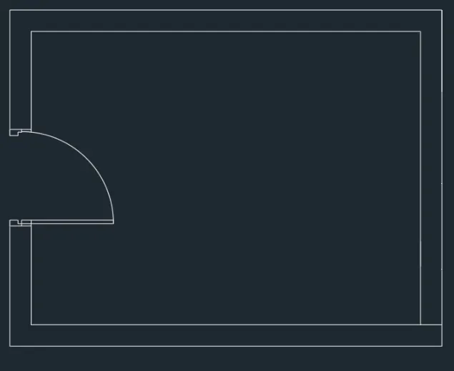
Now in the command prompt type hatch to hatch the model
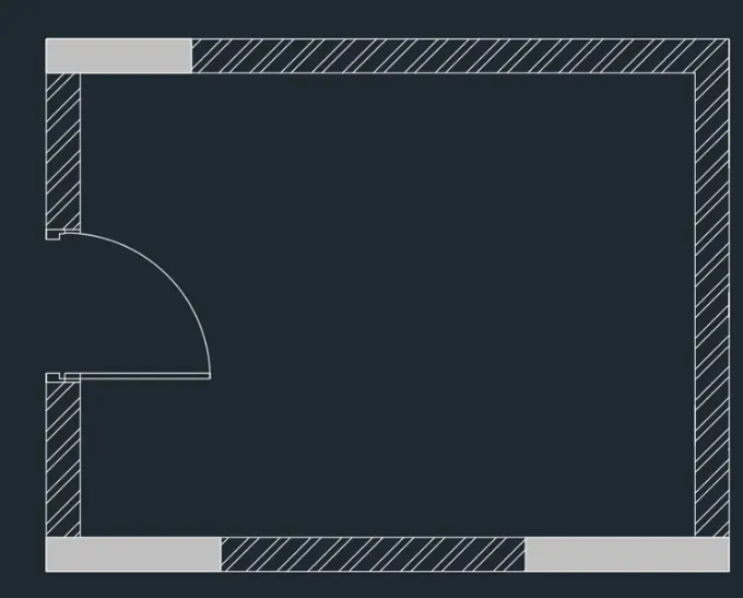
Step 3
In the command prompt type rec and dimensions
In the command prompt type offset and offset it to the desired distance to get the Oven
In the command prompt type trim to trim the extras
In the command prompt type offset and offset it to the horizontal distance of 350,450,900,450,450 and 560
In the command prompt type offset and offset it to the vertical distance of 600
In the command prompt type line type and load the dotted lines
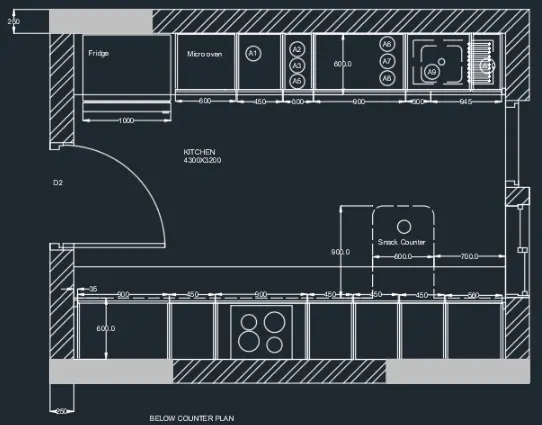
step 4
In the command prompt type text to text the given annotations
Now in the command prompt type dimensions to given the dimensions to your plan
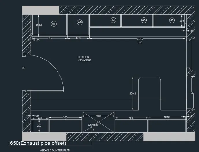
RESULT
Q.4
Ans
AIM To sketch the column details
PROCEDURE
Step 1
Units are set to mm.
Limits and lim-max are also set
Step 2
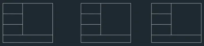
Using rectangle and line command the tables are drawn
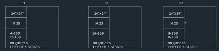
Using text command, the text is given
Step 4
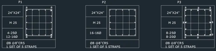
In the command prompt type lines to draw the reinforcement
In the command prompt type circles to draw the reinforcement
RESULT
Q.5
Ans
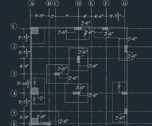
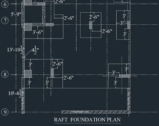
AIM To draw the raft layout
Procedure
Step 1
Units are set to Engineering in inches
Limits and lim-max are also set
Step 2
In the command prompt type rectangle > dimensions are 29'-7" and 60'
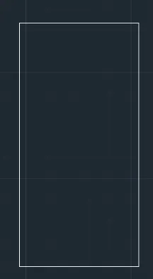
To get dotted lines click on line type and load the dotted lines
With the help of dotted lines and offset command the grids are drawn
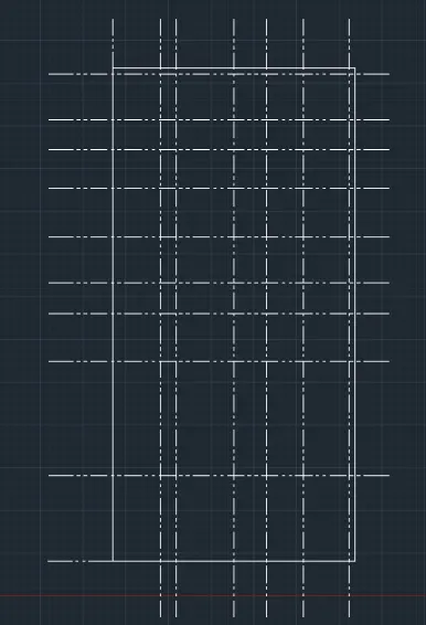
In the command prompt offset the distance to 4"
Use Hatch command and material AR-Conc
In the command prompt type rec 2' x 2'
In the command prompt type rec to draft the columns
In the ribbon bar select hatch and select ANSI37 hatch the columns
In the ribbon bar select hatch and select ANSI33 to hatch the walls
Now put the annotation and dimension in given order
RESULT