Creating a Wardrobe detailed drawing, Floor Plan, Kitchen Layout and Column Detail using AutoCad
1)
Aim :
To draw the elevation and details of a wardrobe by using autocad.
Procedure:
step1:
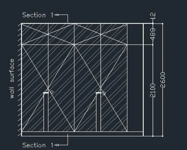
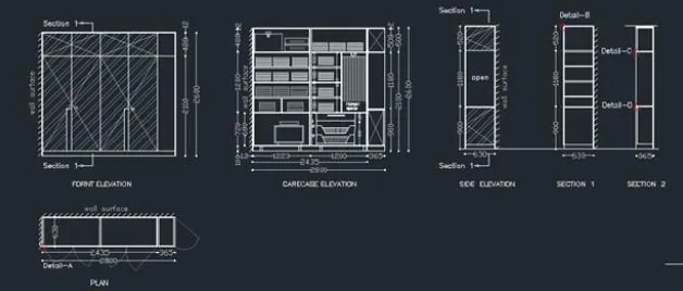
- FRONT ELEVATION
- First set the limits as per required of drawing then set the units as mm Zoom > a
- Make a rectangle of 2800x2600mm
- Take the offset command and take 12mm offset at three sides of rectangle
- Take the offset of 488mm from the top and 100mm from the bottom
- Next take the hatch command take the hatch size as 20mm place the hatch required area with in the close boundary then set the transparency
- Now take the text command and write and edit the text as per required
- Take the dim command and mark the dimensions.
Step2 :
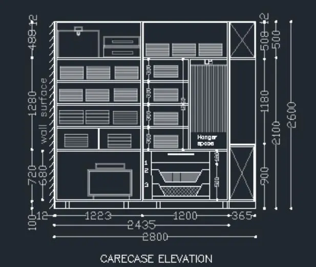
- CARCASE ELEVATION
- First make a rectangle by taking command REC and draw a rectangle of 2800x2600
- Take the offset 12mm for outer sides and 20 offset for innerwalls
- Start the work from bottom to top and left to right as per the provided dimensions
- First take offset of 100mm from bottom to top 680mm, 300mm,300mm,300mm,488 as shown in the drawing
- Draw the interior blocks by using line command then place at the positionsas per the given drawing
- Next apply the transparency unit for all the blocks were placed
- Give the proper dimensions using the "DIMCONTINUE command
- Take the text command write and edit the text were required
Step3 :
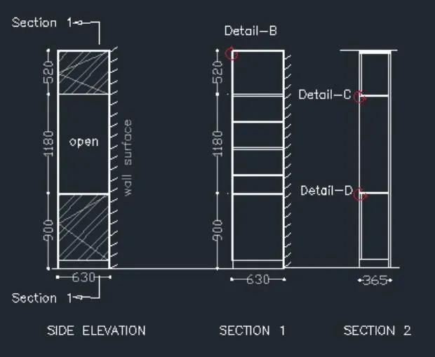
- SIDE ELEVATION
- Draw a rectangle of 630x2600 than start a work from bottom to top
- Take a offset of 10mm from bottom next take a offset of 900mm 1180mm and then 520mm
- Take the offset of 20mm for all the lines take the line command and draw the wall surface area
- Take the hatch command a make a hatch with size of 20mm and apply the transparency
- Give the proper dimensions using the "DIMCONTINUE command
- Take the text command write and edit the text were required
- SECTION 1
- Draw a rectangle of 630x2600 than starta work from bottom to top
- Take a offset of 10mm from bottom next take a offset of 900mm and take offset of 300mm four times inside
- Take the offset of 20mm for all the lines take the line command and draw the wall surface area
- Give the proper dimensions using the DIMCONTINUE command Take the text command write and edit the text were required
- SECTION 2
- Draw a rectangle of 365x2600 than start a work from botom to top
- Take the offset of 100mm from the bottom and 900mm.1180mmand 520mm
- Take the offset of 20mm for all the lines take the line cammang and draw the wall surface area
- Give the proper dimensions using the "DIMCONTINUE command
- Take the text command write and edit the text were requied
Step4:
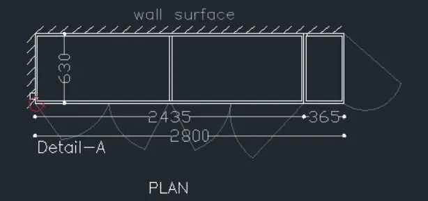
- PLAN
- Draw a rectangle of 2800x630
- Take the offset of 20mm for all the lines take the line command and draw the wall surface area
- Give the proper dimensions using the "DIMCONTINUE" Command
- Take the text command write and edit the text were required
2)
Aim:
To draw the floor plan as given
Introduction:
To draw the floor plan as given by using AutoCAD
Procedure:
Step:1
- First set units by typing the command "UN" select the mm
- Set up the limits as per the required of the drawing
- Import the pdf into your current drawing and start working on the project
- Scale the imported pdf file using reference option
- All dimensions are in mm
Step2:
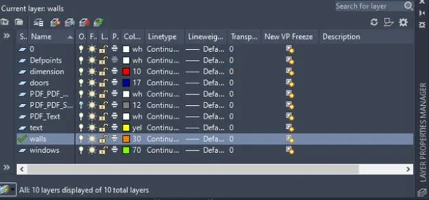
- Create the layers from the layers properties
- Tap on the new layer and create the layers such as walls, text, dimensions, windows, as required
- Select the color for the created layers
Step3:
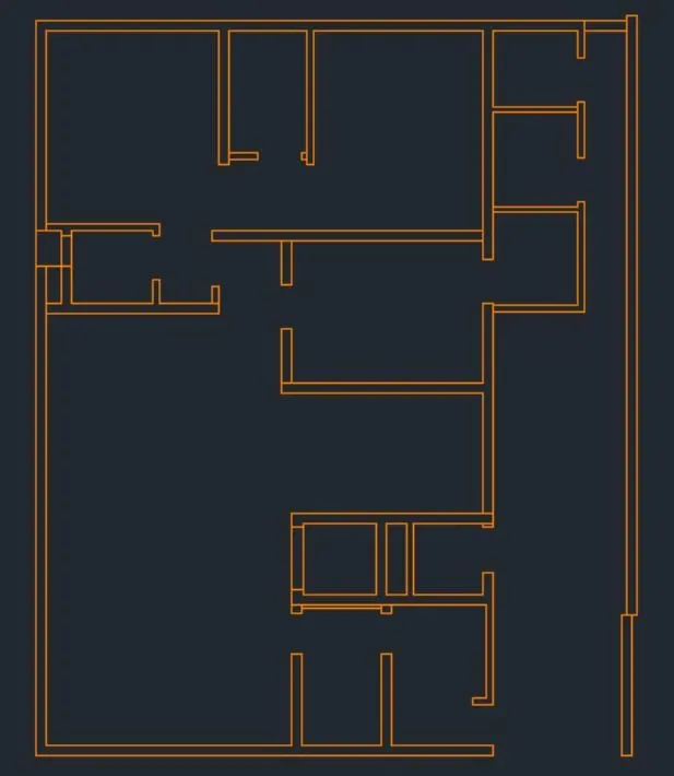
- Creation of external and internal walls
- Set the wall layer as the current layer
- Take the construction line by using the command XL and H for horizontal for vertical
- Start the working on the project from bottom to top and left to right .
- Take all the dimension reference from the given pdf and create all the external and internal walls
Step4:
- Creation of doors, windows, staircase, text, and dimensions
- Take the door by from the shortcut key ctrl3 > architectural>door adjust the wall thickness height length of the door as required and place it in the drawing
- For the creating of windows take the length of the windows mark the first line at first end and second ling at least end mark another line from the mid of the two lines next take the offset.
- Text for the text go to the text command type the text copy reference select the place it at the point edit the text as required
- For Staircase draw a line with the required length of staircase take a offset command for trade take 300mm and for riser the 150mm offset
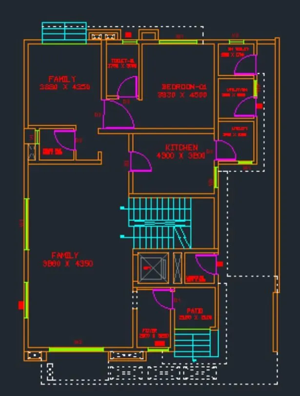
Result :
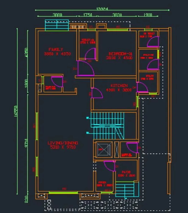
3)
Aim:
To Create the Kitchen Layout
Introduction:
To Create the Kitchen Layout by using AutoCad
Procedure:
Step1:
- Draw a rectangle by typing the command "REC" in command box
- Select the first point give the dimension 4300x3200 230mm in the outer section
- Next take the offset command make an offset
- For the window take the size of windows and make the offset from the external line the wall and trim the extra lines
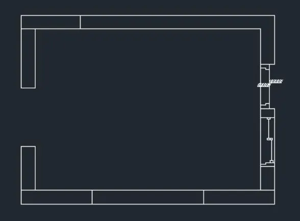
Step2:
- Creation of door and hatches
- For the door take the shortcut key ctrl+3 adjust size of the door as per required take command move and place it at the position
- For the hatches take command hatch select the patten place it in the close boundary adjust the hatch size, angle, and transparency as need.
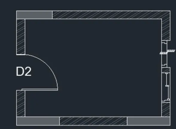
Step3:
- Now take the line command check the dimensions from the refrance drawing draw the given materials or kitchen utility
- Take the offset command for offsetting the lines use "tr command for trim of lines
- For the creation of doted line go the properties option change the line type select the line is discontinues lines
- Next go the property of lines change the size of the transparency.
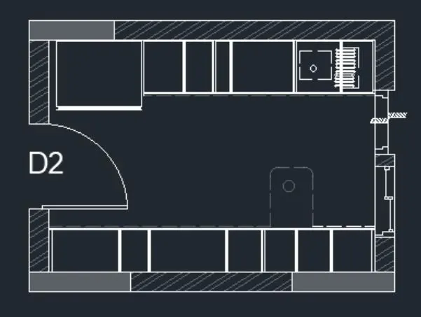
Step4:
- Creation of text and dimensions
- For the creation of text go the mtext command type the text place all the text at the positions edit as per the required
- For the dimensions go to the dim command select the first point and end place the dimension take the continues for all the dimension
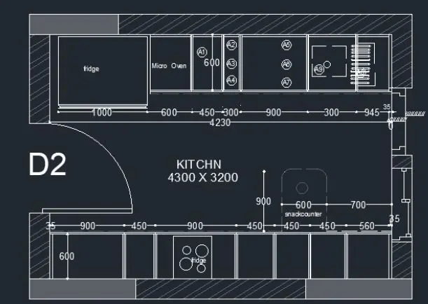
Result:
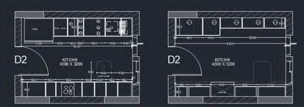
4): Aim:
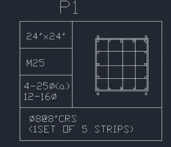
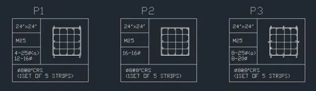
To sketch the column details
Introduction:
To sketch the column details by sing AutoCad
Procedure:
Step1:
- First set the units to un > engineering inches
- Next set the limits as per the requirement f the drawing
- Take the rectangle of 24"x24" by typing "REC" in the command box
- Take the offset command take the offset of the 2" to the outer side

Step2
- Creating and should bars
- Take the circle with tangent, tangent, radius take the two tangent point give the radius for the required of the bar
- 8mm ---- 0.31 Inches
- 25mm---1 inches
- 16mm-0.62 inches
- For the creation of strips take the line command mark a line from the start point and end of the circle of bar
- Write the alphabet for the indicating of size of the bar
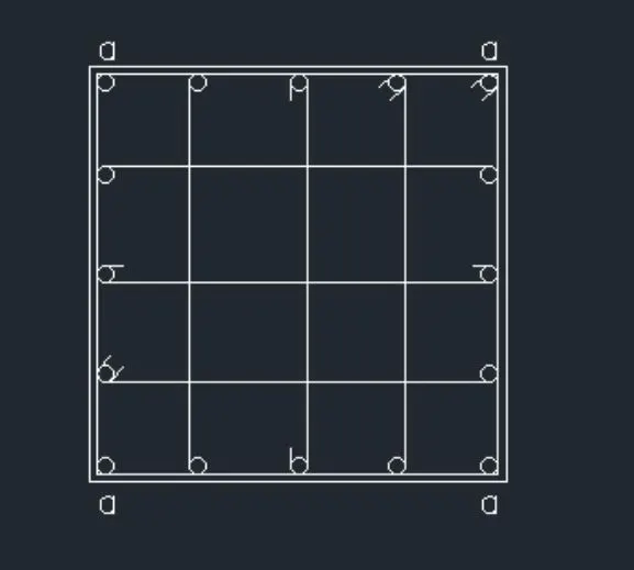
Step3:
- Now take the command m.text give the base point for the text
- Give the size of the text, height of the text, type of the text
- Write the text copy the text place it on its positions edit and write the text as per requirement
Result:
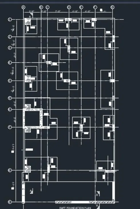
5)
Aim:
To Draw the Raft Layout
Introduction:
To Draw the Raft Layout by using AutoCad
Procedure:
Step1:
- First set the units to imperial and then set the limits as per the requirement of the drawing
- Next import the given pdf into autocad drawing to ensure the missing dimensions
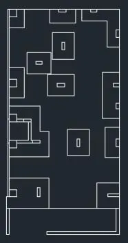
- Select all columns go to the copy command select the base point draw to side for place it

Step2:
- Drawing of footing and walls
- For the footing take the reference from the imported pdf
- By using the line command mark all the footing
- At the bottom draw a wall of 9" thickness as given the pdf
Step3:
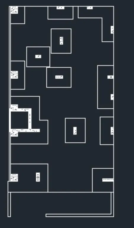
- Now take the hatch command and mark the hatch in all the columns
- Take the hatch mark in all the close boundary of columns and walls
Step4:
- To mark the gride lines select the center line 2
- Next take the line command and select the centerline 2x
- Mark the gride from every center of the columns
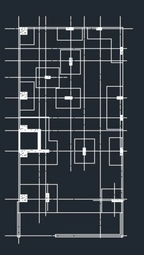
Step5:
- Creation of text and dimension
- First take the circle command draw the circle with the unit 2
- Next take the text command give height of the text as 2
- Now take the copy command select the base point place it on required places
- Next edit the text as per the required of it
Result: