Creating a Wardrobe detailed drawing, Floor Plan, Kitchen Layout and Column Detail using AutoCad
AIM : To Create a Wardrobe detailed drawing, Floor Plan, Kitchen Layout and Column Detail using AutoCad
Introduction and Prerequisite :
- Open autocad application
- Type Qnew and open new drawing
- Set units according to drawing
- Switch on object snap and object snap modes : Endpoint, Midpoint, Center, Nearest, Intersection, Perpendicular and Node
- Ortho mode is ON
Problem 1 :
Aim : To draw the elevation and details of a wardrobe
Procedure :
- Set units to decimal
- Set units in dim style to decimal
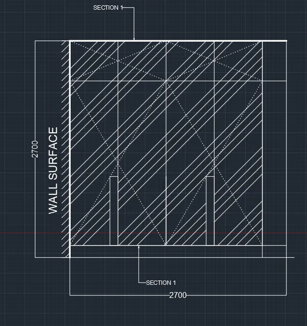
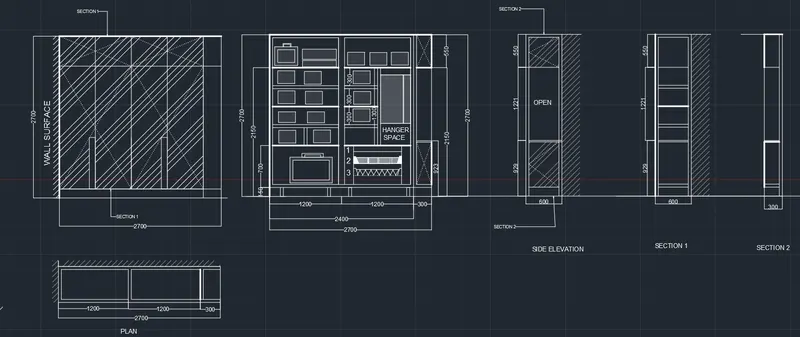
- Draw a square of size 2700 x 2700 mm using line tool
- Draw a line with offset of distance 150 using bottom line of square and another line with offset distance of 500 using top line of square
- Draw four lines with offset distance of 600 using left side of square and trim off lines at bottom
- Draw cross lines as shown in diagram and assign it to new layer i.e. layer 1 (change line type to "ACAD_ISO03W100")
- Draw two rectangles of size 860 x 150 mm as shown in figure
- Now hatch the diagram using pattern "ANS134" and hatch pattern scale 12
- Create anothe layer i.e layer 2 and assign left and top lines (2700 mm lines) to this layer in which line weight of lines are 40mm
- Enter command line weight and click on display line weight
- Extend bottom line (2700mm) to extra 100mm on both sides
- At left side draw a line 90 degree of length 2700mm from extended 100mm line and join to the diagram with another 100mm line (towards right)
- Hatch this newly formed rectangle using pattern "ANS131" and hatch pattern scale 20
- After hatching remove these lines and draw a text "WALL SURFACE" using font style ariel, height 100mm and rotation 90 degree
- Enter "MLEADERSTYLE" and click on modify
- Enter maximum leader points to 3, set landing distance to 35, arrow head symbol as closed blank and arrow head size to 30, press okay and close
- Using "Leader" draw and write a text "SECTION 1" at top and bottom of diagram as shown below
- Using dimlinear mark the dimensions
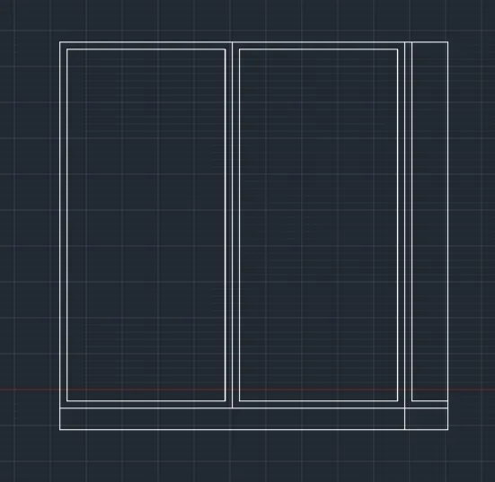
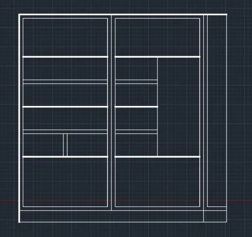
- Draw another square 2700 x 2700 mm
- Draw a line with offset of distance 150 mm using bottom line of square
- Then draw two rectangles of size 1100 x 2450 mm from a distance of 50mm of bottom line and maintaining a gap of 100 mm
- Now make a gap of 100 and draw the third rectangle of size 300 x 2500 mm as shown below
- Now draw shelves in first rectangle
1st shelve of size = 1100 x 500 mm
2nd, 3rd, 4th, 5th shelve of size = 1100 x 300 mm - Create a gap of 50mm and assign some line to layer 2 as shown in fig
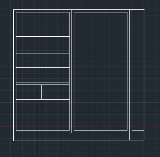
- Now create similar shelve in rectangle 2 as shown in fig
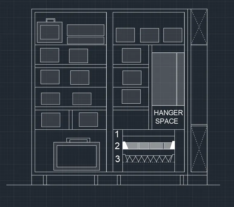
- Draw various boxes in each shelve and a write text "HANGER SPACE" in the 2nd rectangle (HEIGHT 75mm)
- Divide the last shelve of rectangle into 3 shelves as shown in the figure
- Hatch these boxes with solid pattern and hatch transparency 80
- Draw 3 stands at the bottom of cupboard of size 50 x 150 mm
- In the last rectangle draw two rectangles of size 300 x 780 mm (bottom) and 300 x 550 mm (above) as shown below
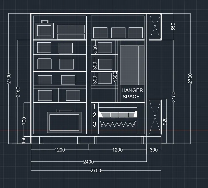
- Now mark the dimensions using dimlinear
- Now draw three rectangles of size 600 x 2700, 600 x 2700 and 300 x 2700 (mm)
- Project the lines from previous drawing to mark the shelves of cupboard
- Name it as side elevation , section1, section 2
- Use hatch tool (pattern ANS131, pattern scale 20) wherever necessary as shown below
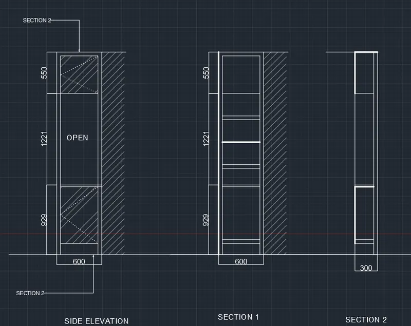
- Draw a rectangle of size 2700 x 600 and draw three small rectangle inside bigger rectangle with gap of 50mm maintained between the rectangles as shown below
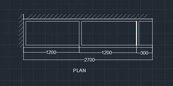
- Hatch (pattern ANS131, pattern scale 20) indicates wall surface and using dimlinear dimensions are marked.
Result :
Problem 2 :
Aim : To draw the floor plan using proper drafting tools
Procedure :
- Set units to decimal
- Set units in dim style to decimal
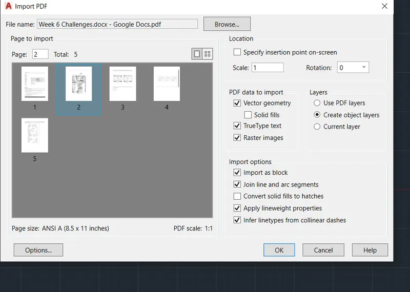
- Enter command "PDFIMPORT" and click on file
- Now select the page of floor plan as shown below
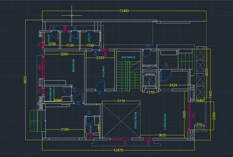
- Now taking the reference of diagram draw the floor plan and adjust the scale of diagram accordingly
- After finishing the drawing remove the imported pdf
- Mark the dimensions of diagram using dimlinear
- Create layers for
1. Windows
2. Doors
3. Dimensions
4. Text (Style arial and height 280mm)
5. Line Type 1 for exterior and interior walls (Solid line)
6. Line Type 2 for dotted line (ACAD_ISO03W100)
7. Staircase
and assign it accordingly to the floor plan
Result :
Problem 3 :
Aim : To create the Kitchen Layout using Autocad
Procedure :
- Set units to decimal
- Set units in dim style to decimal
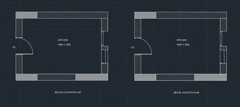
- Draw a rectangle of size 4500 X 3400 and draw a rectangle with offset distance 200mm
- Draw a door of size 760 x 2100 mm as shown in the figure
- Draw a text "KITCHEN 4300 X 3200" at centre of diagram and D2 at the door (style : arial and height 75mm)
- Hatch the wall area with two different patterns as shown below
1. ANS131, SCALE=20
2. SOLID with transparency 50 - Now make two copies of this diagram one is "Below counter plan" and another is "Above counter plan"
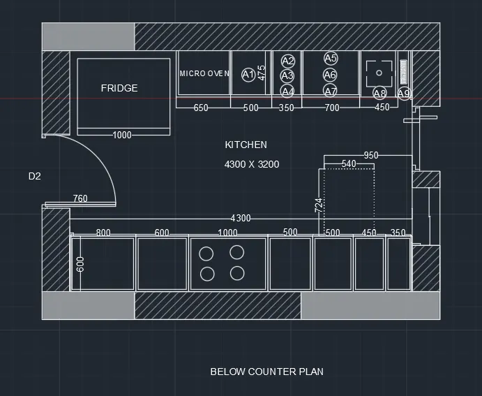
- Now in the below counter plan draw fridge, various sizes of shelves, sink, gas stove using rectangle tool as shown below and also mark the dimensions using dimlinear
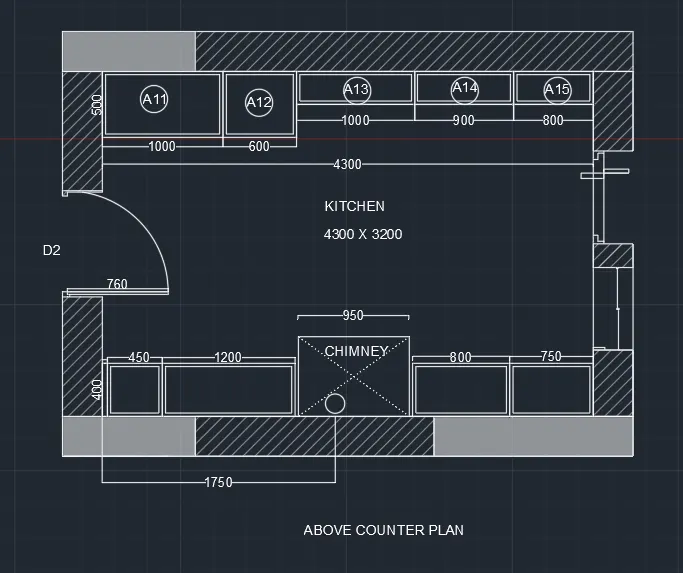
- Similarly in Above counter plan draw various shelves, chimney area using rectangle tool as shown below and also mark the dimensions using dimlinear
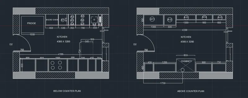
- Text style arial and font height of 75mm is maintained throughout the diagrams
Result :
Problem 4 :
Aim : To sketch the column details using AutoCad
Procedure :
- Set units to engineering
- Set units in dim style to engineering
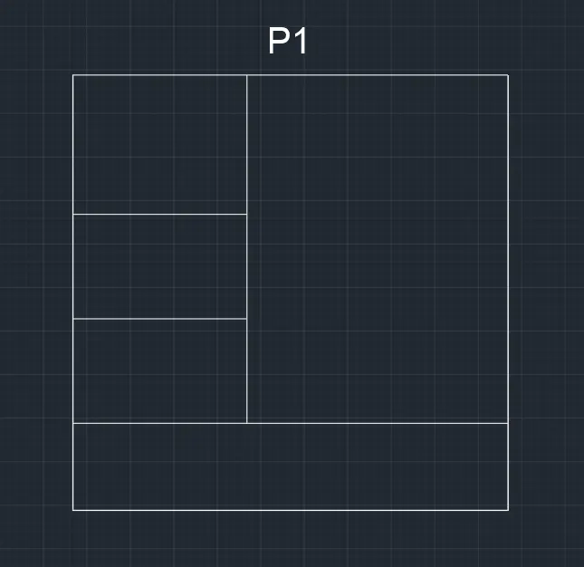
- Draw a square of size 60" x 60"
- Divide the square in rows and column as shown below and name it as P1
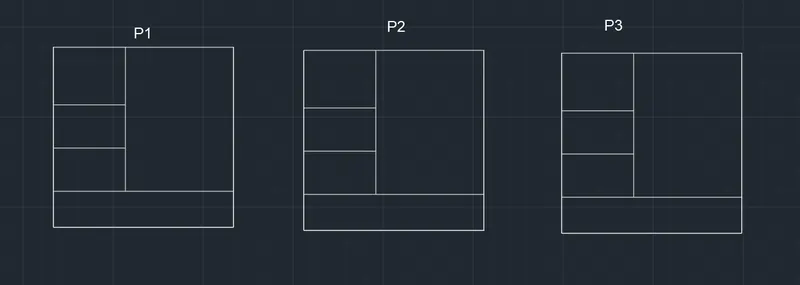
- Make two copies of this diagram P2 and P3 as shown below
- Draw a square of 24" x 24" and draw another rectangle with offset distance 1"
- Inside this square draw three horizontal lines and three vertical lines with offset distance of 5.5"
- Now draw circles along with tangents and hatch them with pattern solid as shown below
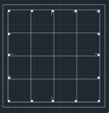
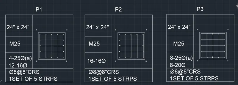
- Place this diagram in P1, P2, P3 squares
- Draw the text with text style arial and font height 4" as shown in the figure
Results :
Problem 5 :
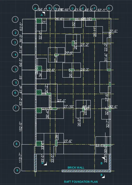
Aim : To draw the Raft Layout as shown in AutoCad
Procedure :
- Set units to engineering and inches
- Set units in dim style to engineering
- Enter command "PDFIMPORT" and click on file
- Now select the page of raft foundation plan as shown below
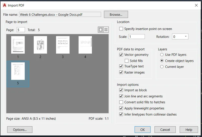
- Now taking the reference of diagram draw the raft foundation plan and adjust the scale of the diagram accordingly as shown below
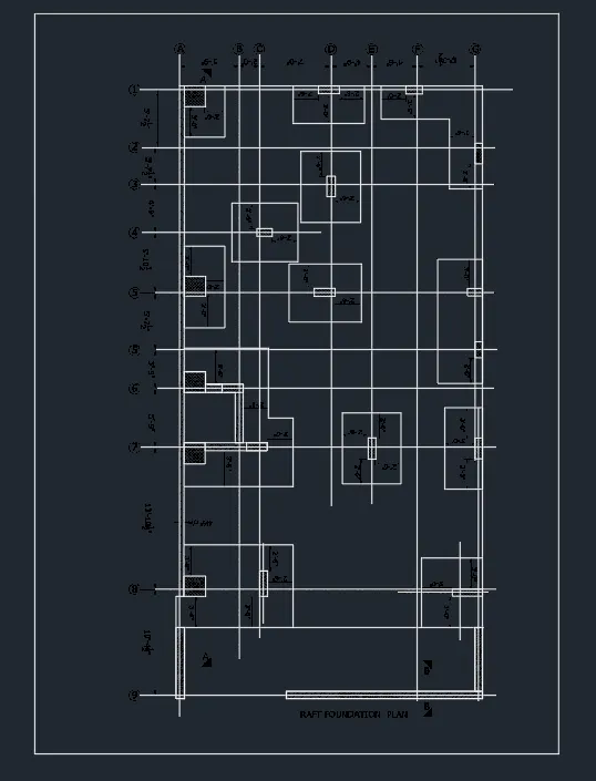
- After finishing the drawing remove the imported pdf
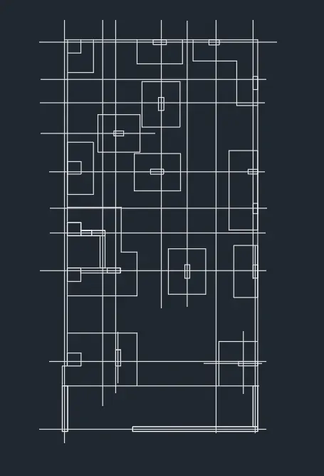
- Mark the dimensions of diagram using dimlinear
- Create layers for
1.Line Type 1 for dotted lines(CENTERX2)
2.Line Type 2 (Continous)
3.Text (style arial and height 8'-4")
4.Dimensions
and assign it accordingly to the raft foundation plan - Hatch the different areas of the plan according to given figure
- Three different hatch patterns are used
1. ANS137 with hatch pattern scale 20
2. AR-CONC with hatch pattern scale 0.6
3. ANS132 with hatch pattern scale 10
Results :