Creating a Wardrobe detailed drawing, Floor Plan, Kitchen Layout and Column Detail using AutoCad
AIM
To draw the following elevation details of the wardrove using autocad.
INTRODUCTION
This Elevation of warddrove is created using autocad and the procedure is explained in detail in each steps and the commands are used in this drawing are.
COMMANDS USED IN THIS DRAWING
- L- LINE
- F8- ORTHO MODE
- GRIDMODE
- F10 - POLAR TRACKING
- ST - STYLE TEXT
- DT-SINGLE TEXT
- T- MULTITEXT
- CO-COPY
- M-MOVE
- T- TEXT
- TR- TRIM
- O-OFFSET
- F- FILLET
- D-DIMENSION STYLE
- Dimcont -DIMCONTINUE
- DIMLIN - DIMLINEAR
- DIMBASE- DIMBASELINE
- LAYON- LAYERS ON
- LAYOFF- LAYERS OFF
- REC-RECTANGLE
PROCEDURE
- open autocad file in windows desktop.
- a dialog box will open it shows startup from scratch.
- click the radio button imperial to start the project.
- in command box type gridmode to show the gridmode by typing 1 in the command box
- type F8 to get ortho on.
- type limmax to set the maximum layout.
- type llmits to set the layout.
- TYPE UN FOR UNITS and set to DECIMAL.
STEP 1
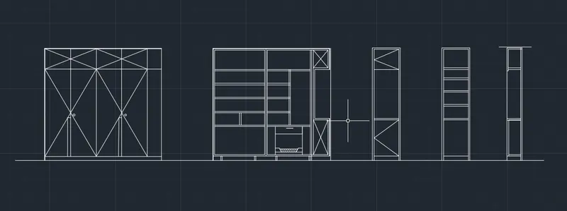
type L-line
using line command the following diagrams are created.
the elevation, section of the ward drove is created.
STEP 2
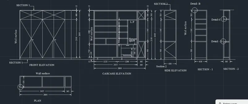
TYPE D- dimension style
set the dimesion style to increase the scale of the dimension.
using Dimlinear to fix the dimension of the particular point.
using Dimcont to easily done the dimension.
using T - Text command to text in the following position.
STEP 3
Type la -layers
to set the layers for the exterior wall, interior wall, text, dimension.
after setting up layers the elevation of layers of the following diagram is done below.
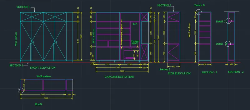
RESULT ; THE following elevation , section of a wardrobe is done as per dimension.
2)
AIM
To draw the following plan using autocad.
INTRODUCTION
This plan is created using autocad and the procedure is explained in detail in each steps and the commands are used in this drawing are.
COMMANDS USED IN THIS DRAWING
- L- LINE
- F8- ORTHO MODE
- GRIDMODE
- F10 - POLAR TRACKING
- ST - STYLE TEXT
- DT-SINGLE TEXT
- T- MULTITEXT
- CO-COPY
- M-MOVE
- T- TEXT
- TR- TRIM
- O-OFFSET
- F- FILLET
- D-DIMENSION STYLE
- Dimcont -DIMCONTINUE
- DIMLIN - DIMLINEAR
- DIMBASE- DIMBASELINE
- LAYON- LAYERS ON
- LAYOFF- LAYERS OFF
- REC-RECTANGLE
PROCEDURE
- open autocad file in windows desktop.
- a dialog box will open it shows startup from scratch.
- click the radio button imperial to start the project.
- in command box type gridmode to show the gridmode by typing 1 in the command box
- type F8 to get ortho on.
- type limmax to set the maximum layout.
- type llmits to set the layout.
- TYPE UN FOR UNITS and set to DECIMAL.
STEP 1
type L-line
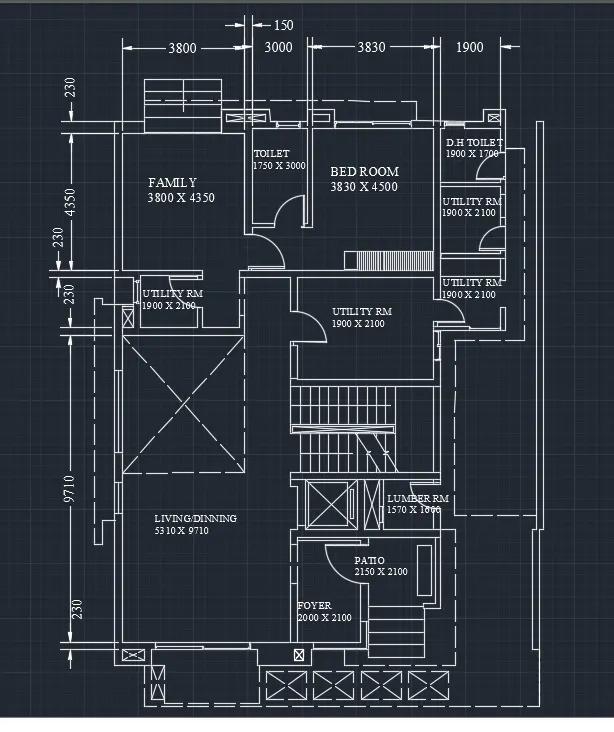
using line command the following diagrams are created.
the plan is drawn in line command.
using text command the text are aligned as per the rooms.
using dimlinear command the dimension are aligned as per plan.
using dimcont the dimcontiue are assigned to the plan.
using linetype the linetype are used in this drawing.
the dimension ,text, lineplan, linetype are used in this drawing.
STEP 2
after adding up layers to the plan.
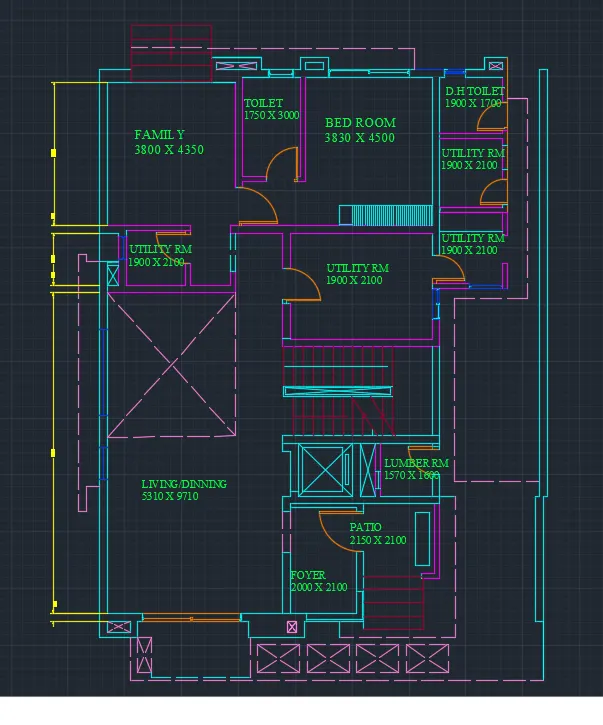
RESULT : THE following plan is done as per dimension is completed.
3)
AIM
To draw the following kitchen plan using autocad.
INTRODUCTION
This kitchen plan is created using autocad and the procedure is explained in detail in each steps and the commands are used in this drawing are.
COMMANDS USED IN THIS DRAWING
- L- LINE
- F8- ORTHO MODE
- GRIDMODE
- F10 - POLAR TRACKING
- ST - STYLE TEXT
- DT-SINGLE TEXT
- T- MULTITEXT
- CO-COPY
- M-MOVE
- T- TEXT
- TR- TRIM
- O-OFFSET
- F- FILLET
- D-DIMENSION STYLE
- Dimcont -DIMCONTINUE
- DIMLIN - DIMLINEAR
- DIMBASE- DIMBASELINE
- LAYON- LAYERS ON
- LAYOFF- LAYERS OFF
- REC-RECTANGLE
PROCEDURE
- open autocad file in windows desktop.
- a dialog box will open it shows startup from scratch.
- click the radio button imperial to start the project.
- in command box type gridmode to show the gridmode by typing 1 in the command box
- type F8 to get ortho on.
- type limmax to set the maximum layout.
- type llmits to set the layout.
- TYPE UN FOR UNITS and set to DECIMAL.
Step 1
Type l- line
using line command the following line of the kitchen plan is drawn.
as per dimension.
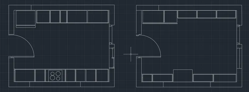
STEP 2
After adding text and dimension as per plan
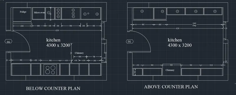
RESULT : THE folowing kitchen plan is done as per dimension is complted.
4)
AIM
To draw the following column rebar using autocad.
INTRODUCTION
This column rebar is created using autocad and the procedure is explained in detail in each steps and the commands are used in this drawing are.
COMMANDS USED IN THIS DRAWING
- L- LINE
- F8- ORTHO MODE
- GRIDMODE
- F10 - POLAR TRACKING
- ST - STYLE TEXT
- DT-SINGLE TEXT
- T- MULTITEXT
- CO-COPY
- M-MOVE
- T- TEXT
- TR- TRIM
- O-OFFSET
- F- FILLET
- D-DIMENSION STYLE
- Dimcont -DIMCONTINUE
- DIMLIN - DIMLINEAR
- DIMBASE- DIMBASELINE
- LAYON- LAYERS ON
- LAYOFF- LAYERS OFF
- REC-RECTANGLE
PROCEDURE
- open autocad file in windows desktop.
- a dialog box will open it shows startup from scratch.
- click the radio button imperial to start the project.
- in command box type gridmode to show the gridmode by typing 1 in the command box
- type F8 to get ortho on.
- type limmax to set the maximum layout.
- type llmits to set the layout.
- TYPE UN FOR UNITS and set to DECIMAL.
STEP 1
type l- line
using the line command the following column rebar is done
using the text command to insert into the text command.
using the fillet command to corner the radius of the command.
using the circle command the circle are drawn into the line as per following.
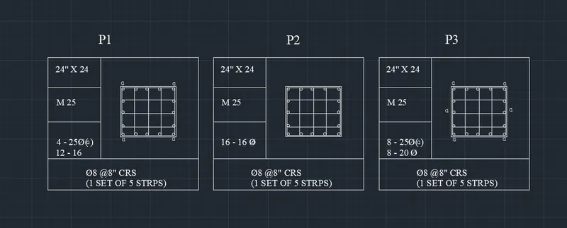
RESULT : THE following column rebar is done as per the following.
5)
AIM
To draw the following Raft layout using autocad.
INTRODUCTION
This Raft layout is created using autocad and the procedure is explained in detail in each steps and the commands are used in this drawing are.
COMMANDS USED IN THIS DRAWING
- L- LINE
- F8- ORTHO MODE
- GRIDMODE
- F10 - POLAR TRACKING
- ST - STYLE TEXT
- DT-SINGLE TEXT
- T- MULTITEXT
- CO-COPY
- M-MOVE
- T- TEXT
- TR- TRIM
- O-OFFSET
- F- FILLET
- D-DIMENSION STYLE
- Dimcont -DIMCONTINUE
- DIMLIN - DIMLINEAR
- DIMBASE- DIMBASELINE
- LAYON- LAYERS ON
- LAYOFF- LAYERS OFF
- REC-RECTANGLE
PROCEDURE
- open autocad file in windows desktop.
- a dialog box will open it shows startup from scratch.
- click the radio button imperial to start the project.
- in command box type gridmode to show the gridmode by typing 1 in the command box
- type F8 to get ortho on.
- type limmax to set the maximum layout.
- type llmits to set the layout.
- TYPE UN FOR UNITS and set to ARCHITECTURAL.
STEP 1.
TYPE L - LINE
the line command is used to draw the raft layout in the foundation.
using the linetype the following diagram is done as per dimension.
using the text command the following text is aligned.
using dimension the center to centere is column is aligned as per dimension.
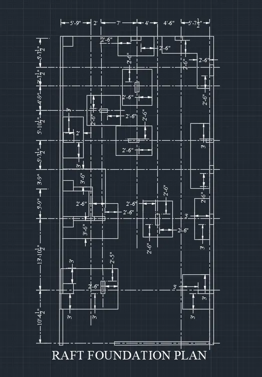
RESULT ; THE following raft foundation plan is done as per dimension is completed.