Creating a Wardrobe detailed drawing, Floor Plan, Kitchen Layout and Column Detail using AutoCad
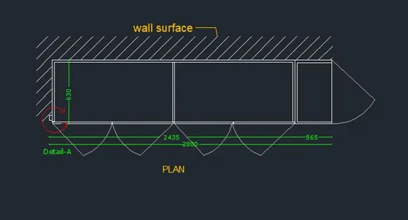
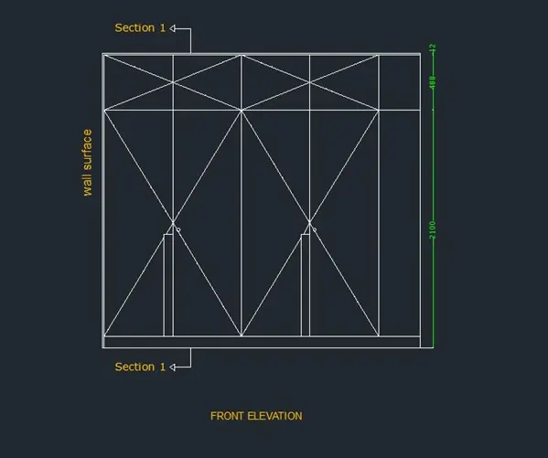
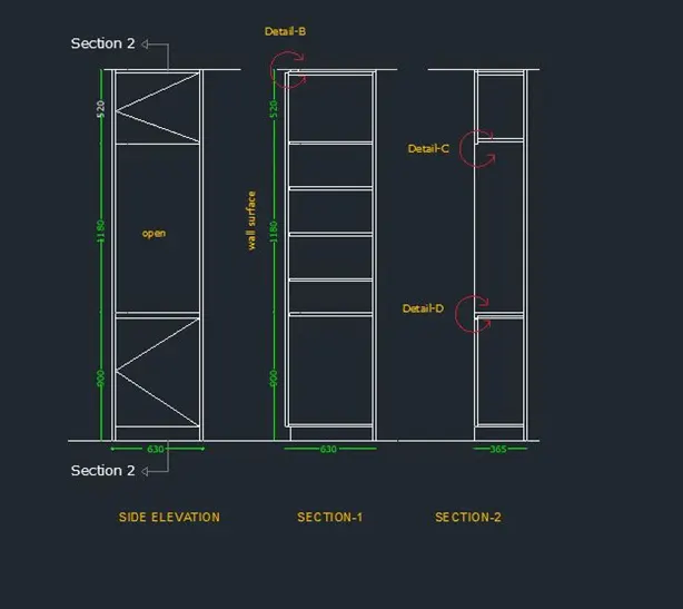
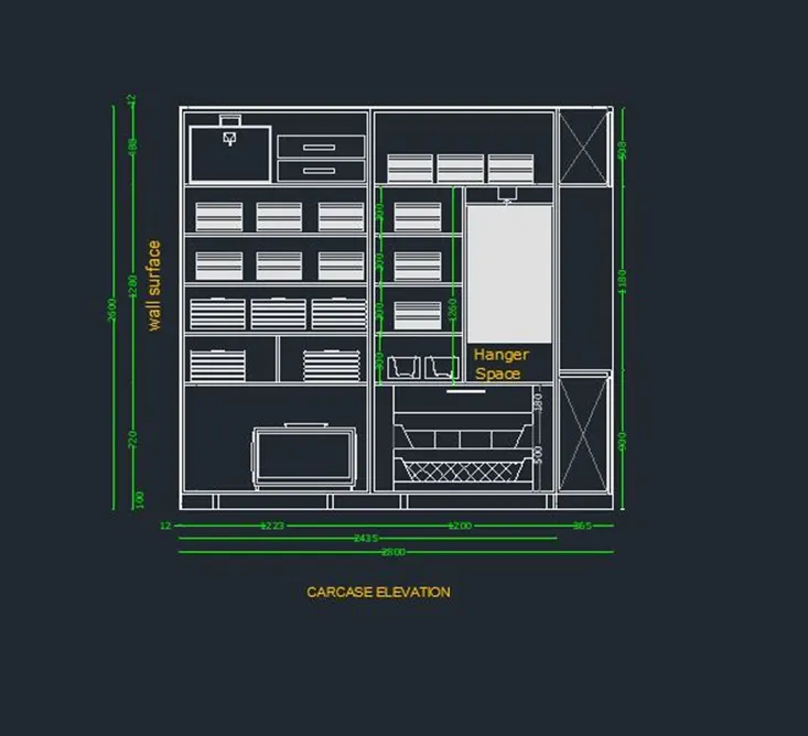
1.) AIM: To draw the elevation and details of a wardrobe as shown in the figure above.
PROCEDURE:
- Both horizontal and vertical lines are used to draw the wardrobe's layout. As shown in figure, the doors of these cabinets are drawn with the use of the arc and line commands.
- With the use of line commands, the front elevation of the same is drawn to the same scale.
- Using a variety of instruments, such as a line to draw the outer casing, the elevation of the carcase is drawn.
- Sections and side elevations are similarly created with the use of lines and offset tolls.
- For simple identification, the dimension and the text are provided on separate layers.
- Later, the unnecessary lines are trimmed and deleted
RESULT:
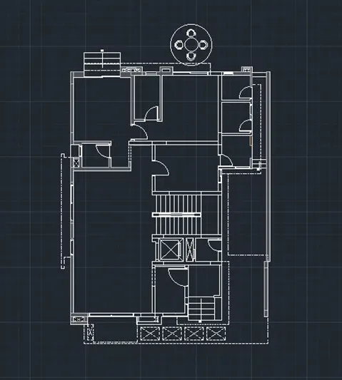
2.) AIM: To draw the floor plan as shown in the Figure.
PROCEDURE:
- Horizontal and vertical construction lines are used to outline the plan's outer boundary.
- Internal walls have an offset of 150mm while external walls have a 230mm offset.
- Using the measurements , a wall offset of either 150 or 230 mm is drawn to create the required-sized room.
Using an arc tool, the doors are drawn.
- After choosing the line type and scaling the line, the dotted lines are drawn.
- Using the circle, line, and arc tools, draw the outside sitting table.
- Unwanted lines are later trimmed and deleted
RESULT:
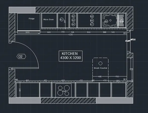
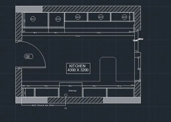
3.) AIM: To create the Kitchen Layout as shown in the Figure below.
PROCEDURE:
- Using horizontal and vertical construction lines, mark the outer edges of the kitchen plan.
- To mark the kitchen walls, a 230mm offset is sketched.
- The kitchen countertops are once more sketched with an offset, and the necessary parts are made in accordance with the specifications.
- Later, the excess and unnecessary lines are trimmed and deleted.
RESULT:
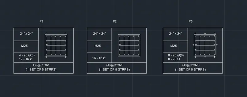
4.) AIM: To sketch the column details as shown in Figure.
PROCEDURE:
- The Columns are drawn of the mentioned size 24"x24" and an offset is provided for the tie to be provided.
- To supply the necessary number of bars, the provided rebars are drawn with the aid of a circle tool, then copied and mirrored evenly around the tie.
- A table is made as illustrated to list the size, concrete grade, and also the rebar provided.
RESULT:
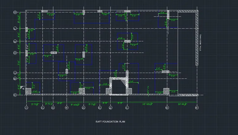
5.) AIM: To draw the raft layout as shown in the figure.
PROCEDURE:
- To precisely locate the columns, grid lines are produced in accordance with the measurements.
- The columns are created in accordance with the measurements taken from the grid lines.
- Draw rectangles and position them over the columns at the necessary spots to create the footing for the columns.
- Where necessary, the cantilever distances from the column edges are modified.
- The extra grid lines and footing lines are trimmed and deleted.
- Hatching is provided to mention the wall and retaining wall for the raft.
RESULT: