Creating a Wardrobe detailed drawing, Floor Plan, Kitchen Layout and Column Detail using AutoCad
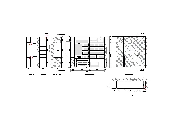
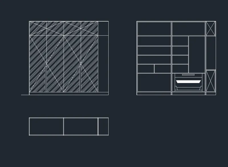
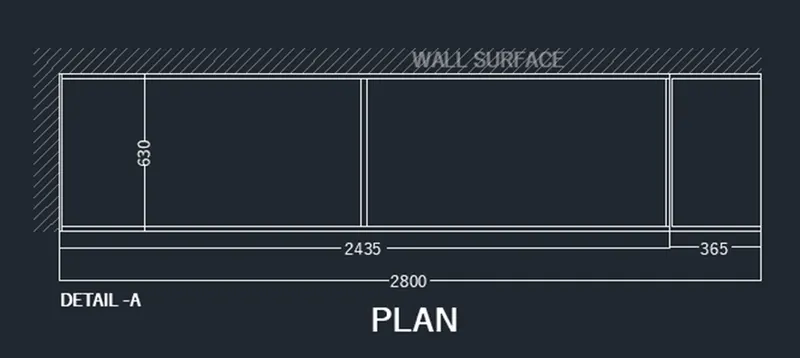
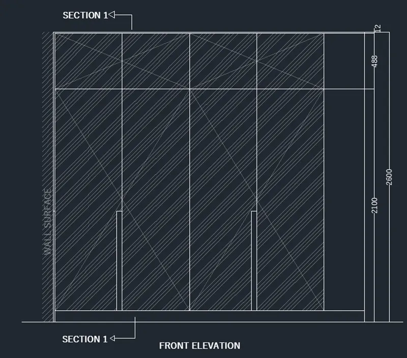
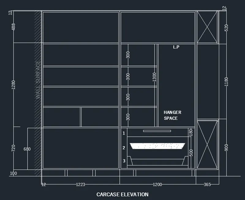
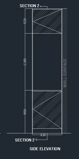
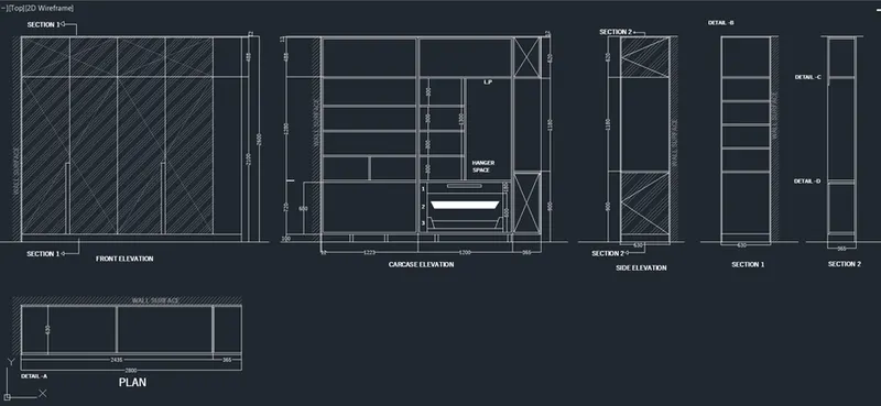
1. Draw the elevation and details of a wardrobe as shown in the Figure below. After sketching, you need to provide the dimensions and text with the use of layers. Use proper text styles and dimension methods to document it. Also, assume dimensions, wherever needed.
Note: All dimensions are in mm.
Aim:
To Draw the elevation and details of a wardrobe as shown in the Figure below.
Introduction :
Various command used while Sketching :
- Line command
- Unit command
- Lim max command
- XL command
- Zoom command
- Arc command
- Trim command
- Text command
- Extent command
- Fillet command
- Rectangle command
- Circle command
- Copy command
- LT command
- Dimension command
- Layer command
- Offset command
- Limits command
PRODUCTRE :
STEP 1 :
- GO to START MENU ,select AutoCAD 2018.
- Enter “UNITS” command in the command tab.
- Open “ Drawing units “ dialogue box , Type as “Decimal ” and precision as 00
- Then click units scale to “ millimetres ”
- Click “OK”.
- Enter “ LIM MAX” command in the command tab.
- Enter new value for Lim max as 20000’.
- Enter “zoom” command in the command box.
- Enter “All” command in the command box.
- Enter “LIMITS” command in the command box.
- Specify lower left corner as 0,0
- Specify right corner as 18000, 18000.
- Enter “zoom “ command in the command box.
- Enter “ALL” command in the command box.
Step 2:
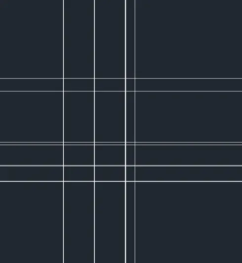
CREATING PLAN :
- Enter “XL “ (OR) “ X line” command in the command box.
- Specific a point as “Vertical” command in the command box.
- Move the line to somewhere , where you want
- Than click “ESC” command in the command box.
- Enter “XL “ (OR) “ X line” command in the command box.
- Specific a point as “Horizontal” command in the command box.
- Move the horizontal line to close to the vertical line.
- Than click “ESC” command in the command box.
- First create plan as per the drawing
- Total length of the wardrobe is per the plan is “2800 mm” in x axis .
- Total thickness of the wardrobe is “630 mm” in y axis .
- Enter “Offset” command in the command box.
- In the side thinness “12mm” as per the given
- In wall surface as per given “100 mm” approximately .

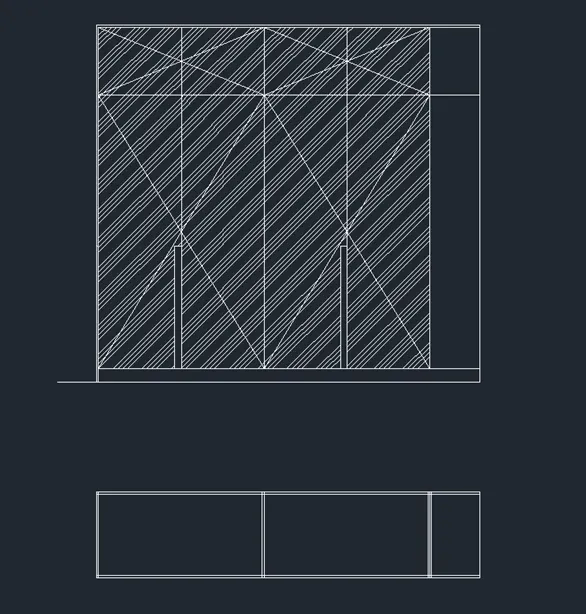
CREATING FRONT EVELVATION :
- Enter we already created vertical lines using “Offset “ command
- Now first will create horizontal lines as per the drawing .
- Enter “Offset “ command from the plan line to front elevation , between the given “1000mm” approximately .
- Enter “offset “ command in the command box .
- Create horizontal lines to previse line value of “ 100mm”
- Total hight of the “FRONT ELEVATION “ is “2600mm”
- Enter “Offset “ command in the command box .
- Give value of “12mm” from the top line.
- Click “ENTER”.
- Enter “OFFSET” command in the command box.
- Give value of “488mm” from the previse line.
- Enter “LINE “ command in the command create like wall inside of the “Front Elevation”
- Enter “LINE” command in the command box .
- Create diamond shape line inside of the wardrobe .
- Then enter “ HATCH” command in the command .
- Give the hatches inside of the front elevation wardrobe .
- Then select the hatches and “RIGHT CLICK” . u will get “option”
- In the option shows “HATCH EDITS “
- After the Right click , u will get the dialoge box “HATCH EDITS”.
- Click “SWATCH” select “ANSI34” .
- Then click “OK”
- After go the scale give value of “200” approximately I given.
CREATING CARSE ELEVATION:
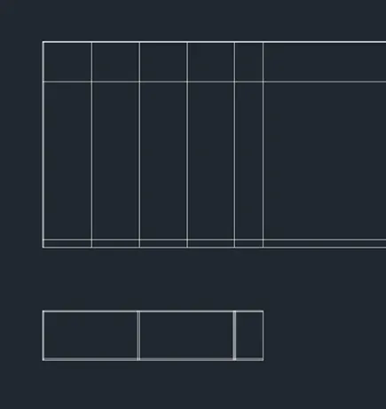
- We already top line and 2nd top line , .
- Enter “Offset “ command in the command box .
- Give a value of “300mm” from the 2nd top line
- Same like that want to crate 4 boxes .
- Enter “Offset” command in the command box.
- From the privies vertical line give value of “1223mm” and “1200mm”
- Enter “TRIM” command in the command box.
- Trimmed unwanted line and give space of “HANGER SPACES “.
- In down side create draw the value of “500mm” and “365mm”.
SIDE ELEVATION :
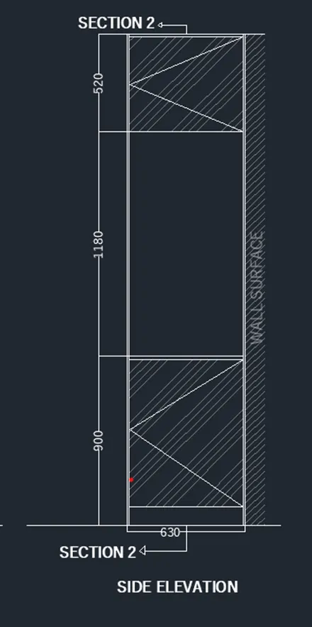
- Create a “ side elevation “.
- Total length of the side elevation is “630mm”
- Total hight of the side elevation is “ 2600mm”
- Enter “Offset” command in the command box.
- Give the value of “900mm” From the first horizontal line.
- After that enter “Offset” command in the command box.
- Give value of “1180mm “ from the privies line.
- Enter “offset” command in the command box.
- Give value of “12mm “ for thinness of cardboard.
- Then enter “ HATCH” command in the command .
- Give the hatches inside of the “Side elevation” wardrobe .
- Then select the hatches and “RIGHT CLICK” . u will get “option”
- In the option shows “HATCH EDITS “
- After the Right click , u will get the dialoge box “HATCH EDITS”.
- Click “SWATCH” select “ANSI34” .
- Then click “OK”
- After go the scale give value of “200” approximately I given
- Use hatch particular places as per the drawing .
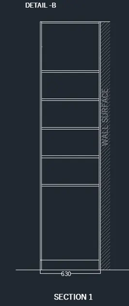
SECTION 1:
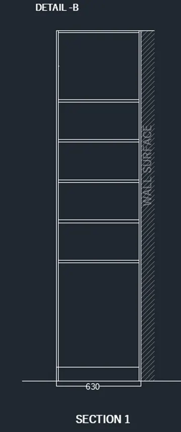
- Enter “OFFSET” command in the command box.
- Create hight of the section value is “ 2600mm”
- Total length of the section 1 is “630mm”
- From the base line give value of “900mm”
- And from privies line to next 4 line give value of “300mm” each lines.
- 2ND last line value as “520 mm” given as per the drawing .
- Wall surface value as “100mm “ approximately.
- Enter “Trim” command in the command box.
- Trimmed unwanted lines and give “12mm” thickness inside of cardboard.
SECTION 2:
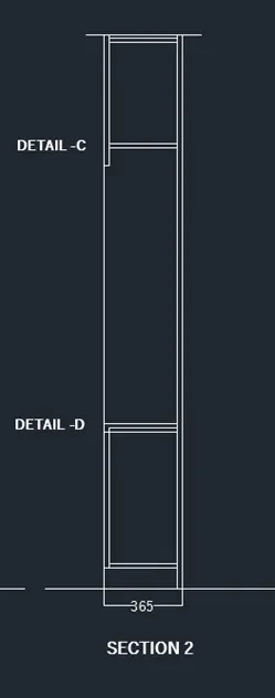
- Creating “SECTION -2” as per the drawing
- Total length of the section -2 is “365mm”
- Total hight of the section -2 is “2600mm” as per the drawing.
- Enter “Offset” command in the command box.
- Give the value of “900mm” from the base line .
- And give the value of”1180mm” in privies line .
- Enter “offset” command in the command box.
- Give a value of “12mm” inside of thickness.
- Enter “TRIM” command in the command box.
- Trimmed unwanted lines.
- Draw the wardrobe as the drawing .
- Enter “DIMLINER” command in the command box.
- Check all value of wardrobe and show dimension as per the drawing
- Finally give show the results as per the drawing .
RESULT:
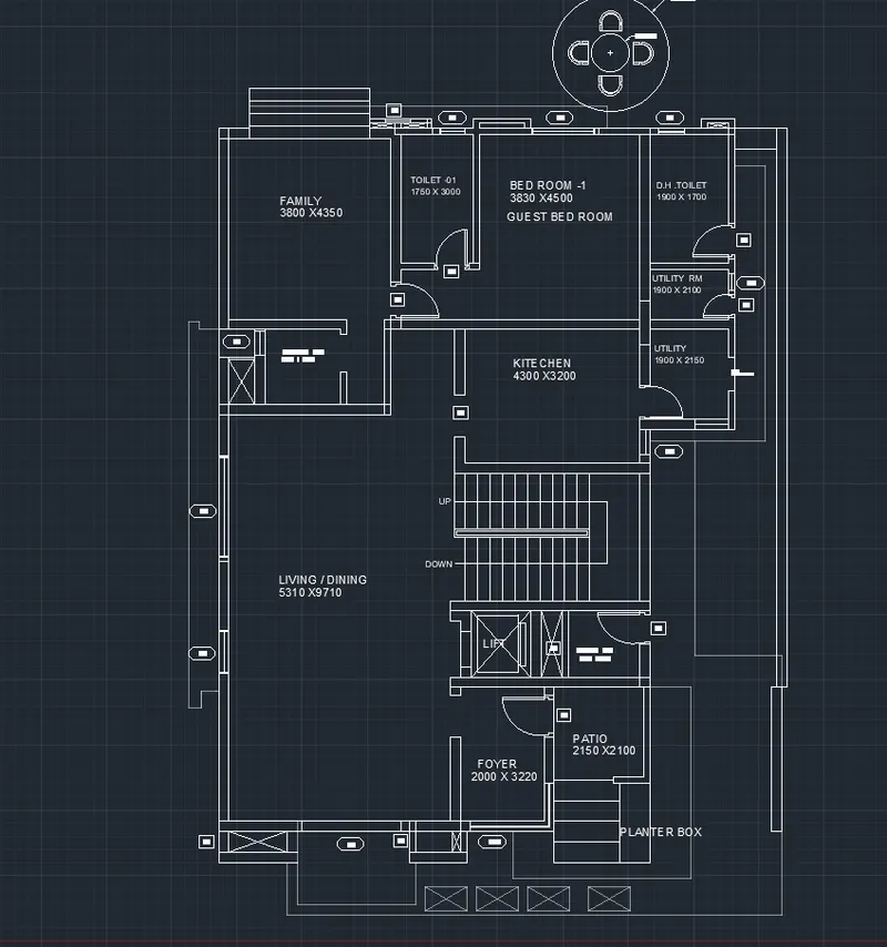
Q2. Draw the floor plan as shown in the Figure. Use the proper drafting tools to sketch the plan. Do not hatch or draw the furniture. You need to draw the floor plan with the following:
Note: You can also import the Floor_Plan.pdf into your current drawing and start working on the project. You need to scale the imported pdf file using reference option. All dimensions are in mm.
- Walls (Exterior and Interior)
Wall Thickness: Exterior Wall- 230mm, Interior Wall: 150 mm (Wherever Required)
- Doors and Windows: Assume the size of the doors and window.
2.1 Stairs: Tread-300mm, Riser-150mm
- Insert Text wherever required
- Insert the dimensions using proper dimension techniques
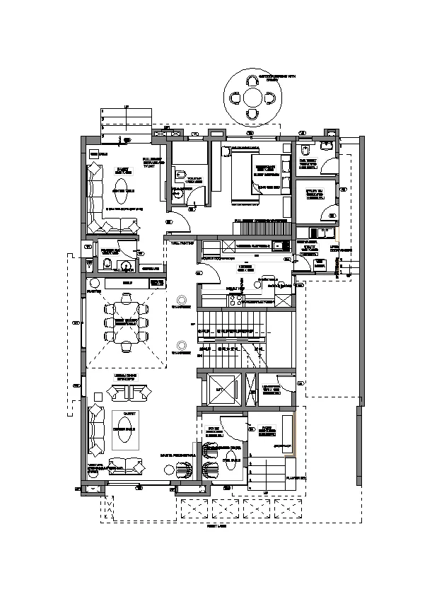
Aim:
To Draw the floor plan as shown in the Figure
Introduction :
Various command used while Sketching :
- Line command
- Unit command
- Lim max command
- XL command
- Zoom command
- Arc command
- Trim command
- Text command
- Extent command
- Fillet command
- Rectangle command
- Circle command
- Copy command
- LT command
- Dimension command
- Layer command
- Offset command
- Limits command
PRODUCTRE :
STEP 1 :
- GO to START MENU ,select AutoCAD 2018.
- Enter “UNITS” command in the command tab.
- Open “ Drawing units “ dialogue box , Type as “Decimal ” and precision as 00
- Then click units scale to “ millimetres ”
- Click “OK”.
- Enter “ LIM MAX” command in the command tab.
- Enter new value for Lim max as 20000’.
- Enter “zoom” command in the command box.
- Enter “All” command in the command box.
- Enter “LIMITS” command in the command box.
- Specify lower left corner as
- Enter “zoom “ command in the command box.
- Enter “ALL” command in the command box.
Step 2:
CREATING PLAN :
- Enter “XL “ (OR) “ X line” command in the command box.
- Specific a point as “Vertical” command in the command box.
- Move the line to somewhere , where you want
- Than click “ESC” command in the command box.
- Enter “XL “ (OR) “ X line” command in the command box.
- Specific a point as “Horizontal” command in the command box.
- Move the horizontal line to close to the vertical line.
- Than click “ESC” command in the command box.
- Enter “offset” command in command box.
- Give a value of “230mm” from the vertical line the thickness.
- First will create family room.
- Enter “offset” command in command box.
- Give a value of “3880” from the wall thickness .
- Enter “OFFSET” command in command box.
- Give a value of “230mm” foe the other side .
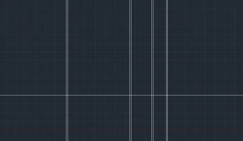
- Enter “OFFSET” command in command box.
- Give a value of “230mm” wall thickness from the horizontal line.
- Enter “OFFSET” command in command box.
- from the horizontal wall thickness , give a value of “4350mm” from the wall thickness of “230mm”.
- now we create the toilet -1
- Enter “OFFSET” command in command box.
- give a value of “1750mm” from the right wall of family room.
- Enter “OFFSET” command in command box.
- Give a value of “150mm” to show the wall thickness.
- Enter “OFFSET” command in command box.
- Give a value of “250mm” from the horizontal line for the wall thickness of toilet on the out side.
- Enter “OFFSET” command in command box.
- Give a value of “3000mm” from the wall thickness .
- Enter “OFFSET” command in command box.
- Give a value of “150mm” to show the wall thickness inside.
- Create a guest bed room .
- Enter “OFFSET” command in command box.
- Draw an offset of toilet wall at distance of “3830mm”
- Enter “OFFSET” command in command box.
- Give a value of “250mm” as wall thickness.
- Enter “OFFSET” command in command box.
- Give a value of “4500mm” from the horizontal line.
- Enter “OFFSET” command in command box.
- Give a value of “250mm” as wall thickness
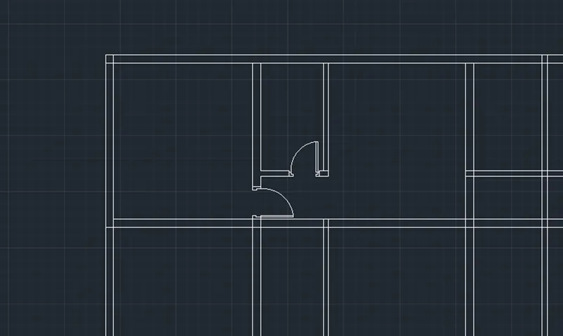
- Draw the D.H. TOILET
- Enter “OFFSET” command in command box.
- give a value of “1900mm” from the gust bed room wall distance right side.
- Enter “OFFSET” command in command box.
- Give a value of “150mm” wall thickness from the privies line.
- Enter “OFFSET” command in command box.
- Give a value of “1700mm” from the horizontal line.
- Enter “OFFSET” command in command box.
- Give a value of “230mm” wall thickness from the privies line.
- Enter “TRIM” command in command box.
- Trimmed unwanted lines in the floor plan.
- Draw the Utility Room
- Enter “OFFSET” command in command box.
- Give a value of “2100mm” downwards the wall of D.H.Toiliet
- Give a value of “150mm” for wall thickness.
- Draw the dishwasher utility.
- Enter “OFFSET” command in command box.
- Give a value of “2150mm”
- Give a value of “150mm” wall thickness.
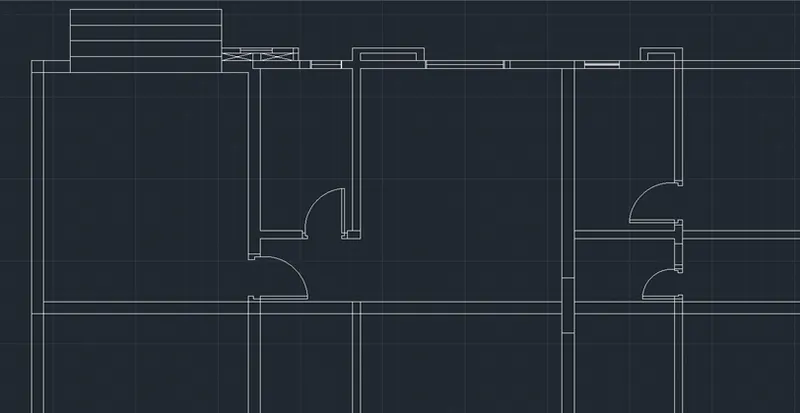
- Draw the kitchen
- Enter “Offset “ command in command box.
- From the left wall of dishwasher utility room , take an offset of “4300mm “ to the left and wall thickness of “250mm”.
- Enter “Offset “ command in command box.
- From the wall of guest bedroom draw an “3200mm” downwards
- Enter “Offset “ command in command box.
- Create wall thickness of “250mm”
- Enter “EXTEND” command in command box.
- Extend the top wall of kitchen up to a distance of “1462mm” excluding the wall thickness.
- Draw cupboard and power room.
- Enter “Offset “ command in command box.
- From the extend line , give a distance of “1000mm” for the cupboard and wall thickness of “150mm”
- Enter “Offset “ command in command box.
- Give a offset of “1800mm” from the wall and also thickness of “250mm”
- Make the above wall of power room as”150mm”
- Enter “Offset “ command in command box.
- Give a offset value of “1650mm” from the wall of bottom
- Draw the living /dining :
- Enter “Offset “ command in command box.
- Give a value of “9710mm” from the wall of power room and also give a value of “250mm”.
- Draw the foyer :
- Enter “Offset “ command in command box.
- Give a offset value of “2000mm” from the wall of living room to the thickness of the wall is “250mm”
- Draw the width of room “3220mm” and offsetting from line extended from the living room
- Enter “Offset “ command in command box.
- give a value of “150mm” wall thickness.
- Enter “Offset “ command in command box.
- Give a offset value of “250mm” for the lift wall and extend it right .
- Draw patio
- Enter “Offset “ command in command box.
- from the wall thickness of “250mm” draw an offset of “2100mm “ downwards .
- Enter “Offset “ command in command box.
- from the wall of foyer draw an offset of “2150mm” and give a wall thickness of “150mm” Right side.
- Draw a lumber room:
- Enter “Offset “ command in command box.
- From the wall of patio draw offset of “1600mm” towards backside.
- Enter “Offset “ command in command box.
- Offset of wall thickness of “250mm” and to the left side give an offset value of “150mm” as wall thickness.
- Draw a duct and lift:
- Enter “Offset “ command in command box.
- Draw an offset of “500mm” from the “150mm” wall of lumber room and wall thickness of “250mm”.
- Enter “Offset “ command in command box.
- Give a offset of “1620mm” from the wall for life .
- Enter “Offset “ command in command box.
- Draw a side walls and front wall of “250mm”
- Draw stairs :
- Enter “Offset “ command in command box.
- Divided the stairs room and offset of “200mm” to two sides by offset from the centre line .
- Enter “Offset “ command in command box.
- draw the first step then offset of “300mm” up to 11 divisions and rest portion forms landing and draw 10 threads on other side division.
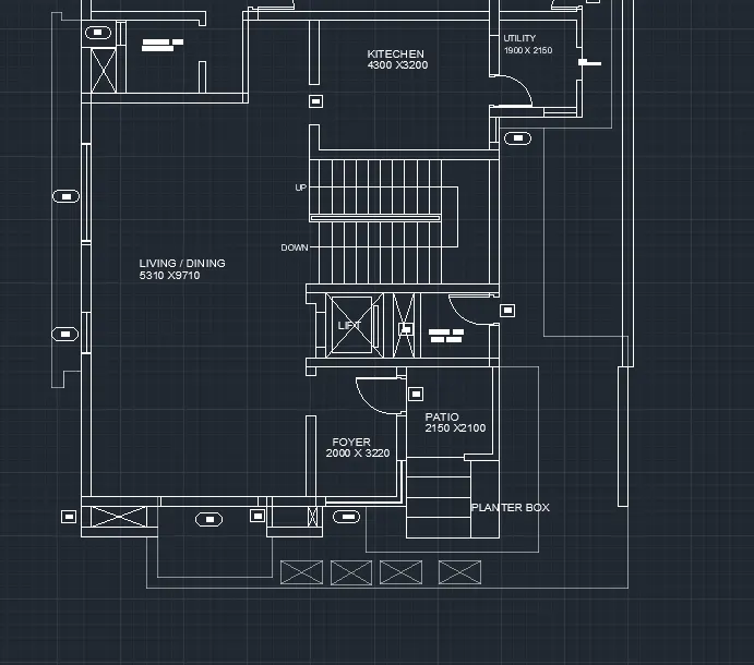
- Create ducts at front and backside
- DOORS , Windows and ventilation are assumed as per the Indian standard .
- Door sizes given : D1- 1000mm, D2-900mm, D3- 900mm, D4-750mm, D5-700mm
- Window sizes given : W1-2700mm, W2-2500mm, W3-900mm, W5-1000mm, W9-800mm.
- Ventilators sizes : V1- 800mm, V2-750mm.
- Enter “DIMLINER” command in command box.
- Dimension all the rooms and wall thickness.
- Enter “MTEXT” command in command box .
- Give a text hight as “200mm” and style as "STANDARD
- Finally shown the results in down .
RESULT:
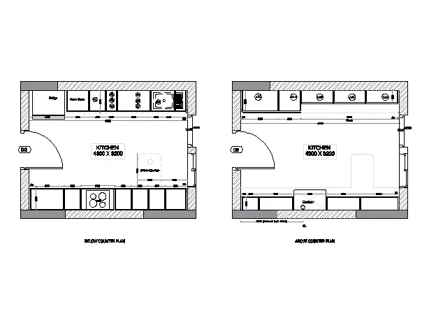
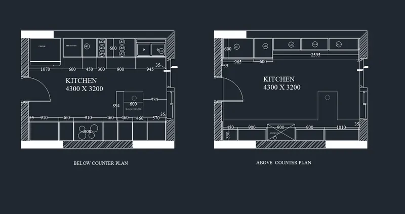
Q3. Create the Kitchen Layout as shown in the Figure below. Also, use proper dimension techniques to dimension the kitchen layout. Also, insert text wherever required. All dimensions are in mm.
Aim:
To Create the Kitchen Layout as shown in the Figure .
Introduction :
Various command used while Sketching :
- Line command
- Unit command
- Lim max command
- XL command
- Zoom command
- Arc command
- Trim command
- Text command
- Extent command
- Fillet command
- Rectangle command
- Circle command
- Copy command
- LT command
- Dimension command
- Layer command
- Offset command
- Limits command
PRODUCTRE :
STEP 1 :
- GO to START MENU ,select AutoCAD 2018.
- Enter “UNITS” command in the command tab.
- Open “ Drawing units “ dialogue box , Type as “Decimal ” and precision as 00
- Then click units scale to “ millimetres ”
- Click “OK”.
- Enter “ LIM MAX” command in the command tab.
- Enter new value for Lim max as 30000’.
- Enter “zoom” command in the command box.
- Enter “All” command in the command box.
- Enter “LIMITS” command in the command box.
- Specify lower left corner as “0,0”
- Specify right corner as “28000,28000”
- Enter “zoom “ command in the command box.
- Enter “ALL” command in the command box.
Step 2:
CREATING Kitchen:
- Creating counter plan
- Enter “REC” command in the command box.
- Give a value of “4300x 3200mm” rectangle box.
- Enter “Offset” command in the command box.
- Give a value of “230mm” wall thickness in outside of the box.
- Creating left cabinet and fridge
- Draw fridge by using rectangle command
- Enter “OFFSET” command in the command box.
- Give value of “1000mm” abd start drawing slabs showing cabinet below.
- Enter “OFFSET” command in the command box.
- Give a value of “600mm” for cabinet below for microwave oven and give an offset of “20mm”
- Enter “OFFSET” command in the command box.
- For width of cabinet give an offset of “600mm” and “20mm” inside and 10mm offset for thickness.
- Enter “OFFSET” command in the command box.
- From “600mm” offset give an offset for A1
- Enter “OFFSET” command in the command box
- Give a value of “300mm” offset for A2,A3,A4.
- Enter “OFFSET” command in the command box.
- Give a value of “300mm” offset for A5,A6,A7.
- Enter “OFFSET” command in the command box.
- Give a offset value of “35mm” from the left and create hinge.
- Enter “OFFSET” command in the command box.
- Give a offset value of “20mm” thickness inside .
- Draw a right cabinet and hob:
- Enter “OFFSET” command in the command box.
- give a value of “35mm” from the left and crating hinge .
- for width of cabinet give a value of “600mm” and “20mm” inside
- Enter “OFFSET” command in the command box.
- Give a value of “10mm” offset for thickness.
- Enter “OFFSET” command in the command box.
- From “35mm” give an offset value of “900mm”
- Give a offset value of “450mm” from the “900mm” and again offset a distance of “900mm”
- Enter “OFFSET” command in the command box.
- Give a offset of distance “450mm” three times from the previous offset
- From the right side offset “35mm” for hinge and rest distance of will be “630mm” which shows the top cabinet .
- Hob is a drawn by rectangle and circle tool in the plan of third cabinet.
- Enter “OFFSET” command in the command box.
- Draw the snack counter by giving offset distance of “700mm” from the left side of wall and “900mm” from the “600mm” width of cabinet
- Enter “FILLET” command in the command box.
- Give a value of 10mm radius
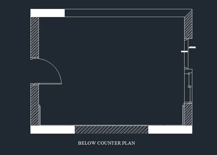
- Draw the counter plan:
- Copy the wall of below counter plan
- Draw the right side counter .
- Enter “OFFSET” command in the command box.
- Draw a width of “350mm” from the wall to inside offset “20mm”
- Enter “OFFSET” command in the command box.
- Offset a distance of “35mm” from the left side of wall.
- Enter “OFFSET” command in the command box.
- Give a value of “450mm” for the top of the cabinet .
- Enter “OFFSET” command in the command box.
- Give a value of “900mm” , 3times for next cabinet .
- Enter “OFFSET” command in the command box.
- For the second “900mm”.
- Enter “REC” command in the command box.
- Draw a rectangle value of “1650mm” from the left side of wall.
- Draw a circle for chimney .
- Draw a left side counter .
- Enter “OFFSET” command in the command box.
- Give a offset value of “35mm”
- Enter “OFFSET” command in the command box.
- Give a value “600mm” offset as width from horizontal wall.
- Enter “OFFSET” command in the command box.
- Give a value of “10mm” offset to show the door.
- Enter “OFFSET” command in the command box.
- From the 35mm hinge offset of “965mm” to the right
- Enter “OFFSET” command in the command box.
- From that offset of “600mm” for the next cabinet
- Enter “OFFSET” command in the command box.
- Give a offset value of “35mm” from the right
- Rest of distance is “2665mm” which is divided intro 3equal parts A13, A14, A15.
- Enter “OFFSET” command in the command box.
- Give a value of “20mm” on both sides of divisions and also “20mm” in front for doors.
- Enter “OFFSET” command in the command box.
- give a value of “10mm” in backside for thickness .
- draw a doors , sliding doors and windows
- sizes of doors is “900mm” width of high is”20mm”
- window of width “900mm”
- Enter “OFFSET” command in the command box.
- For the sliding door take “200mm” of offset from the window and giving an opening of “900mm”
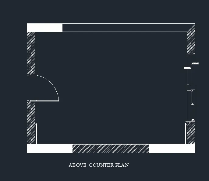
- Enter “DIMLINER” command in command box.
- Dimension all the rooms and wall thickness.
- Enter “MTEXT” command in command box .
- Give a text hight as “200mm” and style as "TIMES NEW ROMAN".
- Finally shown the results in down .
RESULT :
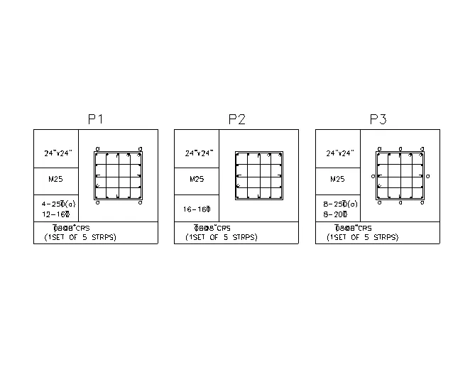
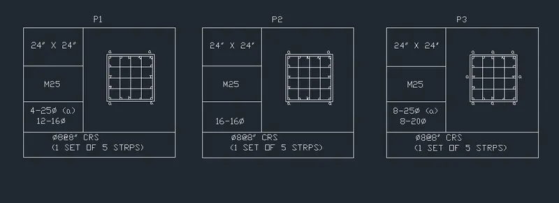
Q4. Sketch the column details as shown in Figure. Insert dimensions and text in the figure. Refer to the bar sizes from the schedule.
8mm ---- 0.31 Inches
25mm--- 1 inches
16mm—0.62 inches
Aim:
To Sketch the column details as shown in Figure.
Introduction :
Various command used while Sketching :
- Line command
- Unit command
- Lim max command
- XL command
- Zoom command
- Arc command
- Trim command
- Text command
- Extent command
- Fillet command
- Rectangle command
- Circle command
- Copy command
- LT command
- Dimension command
- Layer command
- Offset command
- Limits command
PRODUCTRE :
STEP 1 :
- GO to START MENU ,select AutoCAD 2018.
- Enter “UNITS” command in the command tab.
- Open “ Drawing units “ dialogue box , Type as “ENGINEERING ” and precision as 00
- Then click units scale to “ INCHES ”
- Click “OK”.
- Enter “ LIM MAX” command in the command tab.
- Enter new value for Lim max as 200’.
- Enter “zoom” command in the command box.
- Enter “All” command in the command box.
- Enter “LIMITS” command in the command box.
- Specify lower left corner as 0,0
- Specify right corner as 170’,170’.
- Enter “zoom “ command in the command box.
- Enter “ALL” command in the command box.
Step 2:
STEP 2:
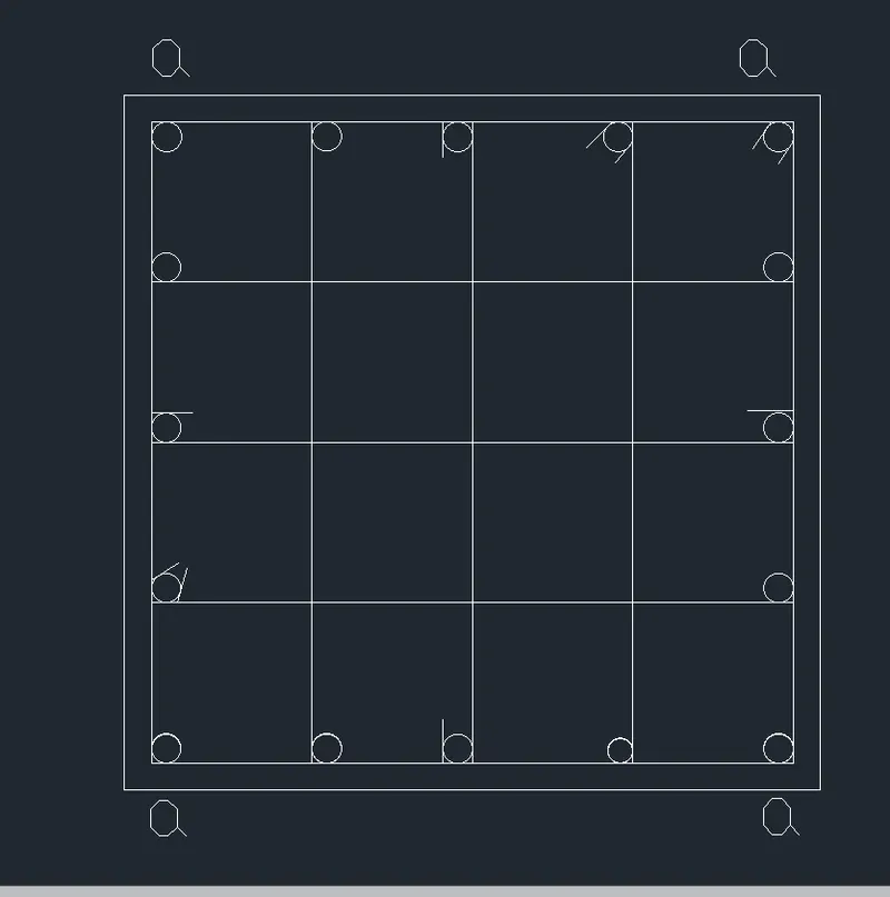
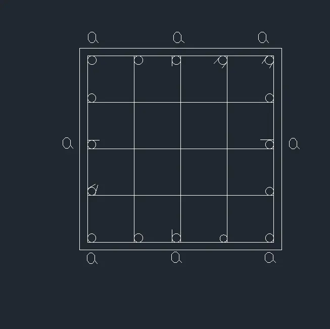
- For column P1 size of 24"X24" having 25mm dia reinforcement at 4 corners and 16 mm dia 12 reinforcement bars in between connected by 8mm dia stirrup.
- Enter “REC” command in the command box.
- Give a rectangle value of 24”x24” in the command box.
- Enter “OFFSET” command in the command box.
- Give a offset value of 5” Which will be the cover of concrete
- Explode the inner rectangle using explode command.
- Now we draw the reinforcements:
- Enter “circle “ command in the command box.
- Select “tan tan radius “ give a radius of 5”
- Enter “MIRROR” command in the command box.
- As the four corners are having 25mm diameter bars mirror the circles in both the directions.
- Enter “divide” command in the command box.
- Using divide command divide the left line into 4 segments
- type "DDPTYPE" to make the points visible.
- Create a circle with “ center radius” as 31 and place the side of the circle in the center of the point.
- Copy the two circle and place it in the position of the points.
- Enter “MIRROR” command in the command box.
- Now mirror the 16mm dia bars by vertical mirror plane.
- Repeat the same process for the horizontal line for drawing 16mm bars.
- Connect the bars by 8mm stirrups by using line command.
- Enter “Donut” command in the command box.
- Now using the donut command fill the circles.
- Specify the inner dia as 0 and outer dia as 8" for the corner reinforcement and 1" for the corner reinforcement and 0.62" for inside reinforcement.
- Mark "a" for in between reinforcement to indicate it as 25mm diameter.
- Enter “MTEXT” command in the command box.
- Text Hight as 2” and text style as
- Create the column to indicate the size of column, grade of concrete and reinforcement details using multiline text
STEP:3
2.For column P2 size of 24"X24" having 16mm dia reinforcement bars connected by 8mm dia stirrup.
- Enter “REC” command in the command box.
- Give a rectangle value of 24”x24” in the command box.
- Enter “OFFSET” command in the command box.
- Give a offset value of 5” Which will be the cover of concrete
- Explode the inner rectangle using explode command.
- Now we draw the reinforcements:
- Enter “circle “ command in the command box.
- Select “tan tan radius “ give a radius of 31”
- Enter “MIRROR” command in the command box.
- As the four corners are having 25mm diameter bars mirror the circles in both the directions.
- Enter “divide” command in the command box.
- Using divide command divide the left line into 4 segments
- type "DDPTYPE" to make the points visible.
- Copy the two circle and place it in the position of the points.
- Enter “MIRROR” command in the command box.
- Now mirror the 16mm dia bars by vertical mirror plane.
- Repeat the same process for the horizontal line for drawing 16mm bars.
- Connect the bars by 8mm stirrups by using line command.
- Enter “Donut” command in the command box.
- Now using the donut command fill the circles.
- Specify the inner dia as 0 and outer dia as 31" for the corner reinforcement and 1" for the corner reinforcement and 0.62" for inside reinforcement.
- Specify the inner dia as 0 and outer dia as 8" for the corner reinforcement and 1" for the corner reinforcement and 0.62" for inside reinforcement.
- Mark "a" for in between reinforcement to indicate it as 25mm diameter.
- Enter “MTEXT” command in the command box.
- Text Hight as 2” and text style as
- Create the column to indicate the size of column, grade of concrete and reinforcement details using multiline text
STEP:4
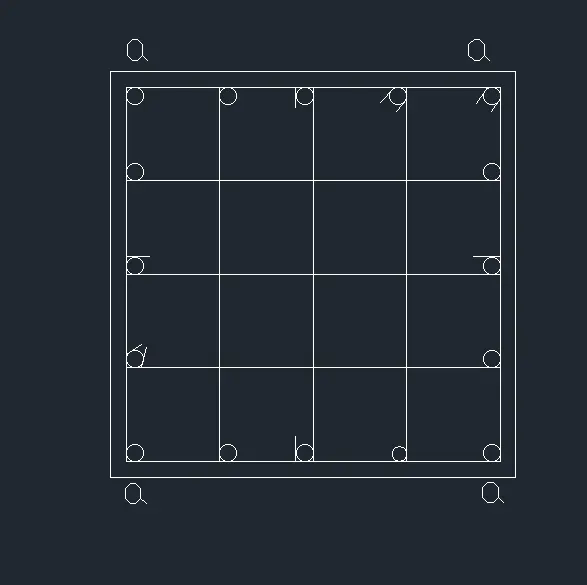
3.For column P3 size of 24"X24" having 8 bars of 25mm dia and 8 bars of 20mm dia connected by 8mm dia stirrup.
- Enter “REC” command in the command box.
- Give a rectangle value of 24”x24” in the command box.
- Enter “OFFSET” command in the command box.
- Give a offset value of 5” Which will be the cover of concrete
- Explode the inner rectangle using explode command.
- Now we draw the reinforcements
- Enter “circle “ command in the command box.
- Select “tan tan radius “ give a radius of 5”
- Enter “MIRROR” command in the command box.
- As the four corners are having 25mm diameter bars mirror the circles in both the directions.
- Enter “divide” command in the command box.
- Using divide command divide the left line into 4 segments
- type "DDPTYPE" to make the points visible
- Copy the 25mm diameter circle to the middle vertical and horizontal bars.
- Now create a circle of with center if radius 0.39" and place the side of circle with center of point.
- Copy the two circle and place it in the position of the rest of the points.
- Enter “MIRROR “ command in the command box.
- Mirror the 20mm diameter bars by drawing vertical mirror plane and delete the points created.
- Again divide the horizontal lines into 4 segments and copy the circle and place the side of circle in the center of the point.
- Connect the bars by 8mm stirrups by using line command.
- Enter “DONUT” command in the command box.
- Now using the donut command fill the circles.
- Specify the inner dia as 0 and outer dia as 0.1" for 8 25mm reinforcement and 0.78" for rest of the 8 reinforcement specify the center of the donut and it gets filled.
- Enter “MTEXT” command in the command box.
- Text Hight as 2” and text style as "ANNOTATIVE
- Create the column to indicate the size of column, grade of concrete and reinforcement details using multiline text
RESULTS:
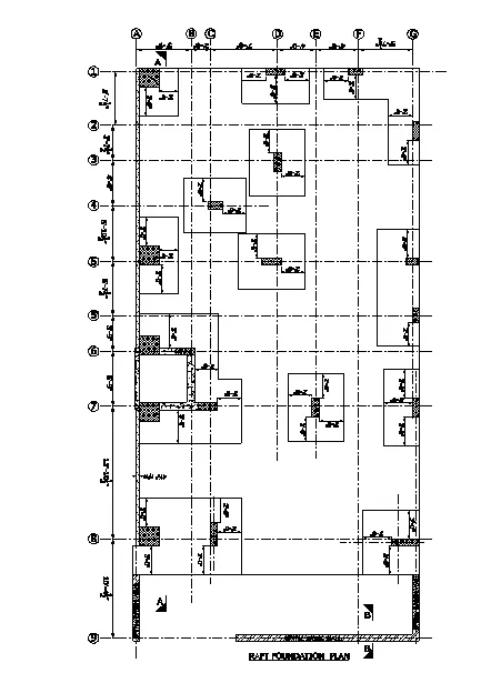
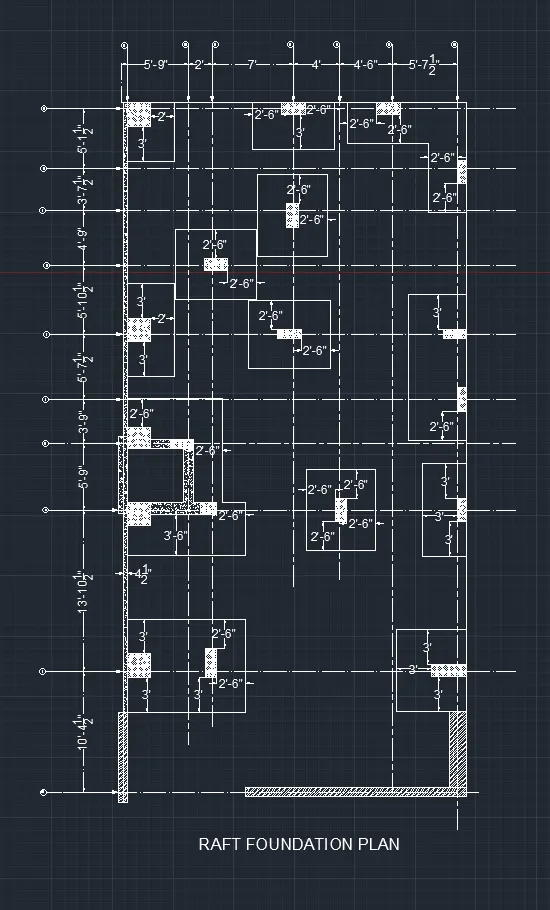
Q 5. Draw the Raft Layout as shown in the Figure. Assume the column size as per your knowledge. You can take the sizes as: 24”x24”, 9” x 24”, 9” x 18”, and 9’ x 24”. You can import the raft_foundation.pdf to ensure the missing dimensions.
Aim:
To Draw the Raft Layout as shown in the Figure
Introduction :
Various command used while Sketching :
- Line command
- Unit command
- Lim max command
- XL command
- Zoom command
- Arc command
- Trim command
- Text command
- Extent command
- Fillet command
- Rectangle command
- Circle command
- Copy command
- LT command
- Dimension command
- Layer command
- Offset command
- Limits command
PRODUCTRE :
STEP 1 :
- GO to START MENU ,select AutoCAD 2018.
- Enter “UNITS” command in the command tab.
- Open “ Drawing units “ dialogue box , Type as “ARCETIURAL ” and precision as 00
- Then click units scale to “ INCHES ”
- Click “OK”.
- Enter “ LIM MAX” command in the command tab.
- Enter new value for Lim max as 200’.
- Enter “zoom” command in the command box.
- Enter “All” command in the command box.
- Enter “LIMITS” command in the command box.
- Specify lower left corner as 0,0
- Specify right corner as 180’,180’.
- Enter “zoom “ command in the command box.
- Enter “ALL” command in the command box.
Step 2:
- Enter “XL “ (OR) “ X line” command in the command box.
- Specific a point as “Vertical” command in the command box.
- Move the line to somewhere , where you want
- Than click “ESC” command in the command box.
- Enter “XL “ (OR) “ X line” command in the command box.
- Specific a point as “Horizontal” command in the command box.
- Move the horizontal line to close to the vertical line.
- Than click “ESC” command in the command
- First create from vertical lines
- Enter “OFFSET” command in the command box.
- From the “A” to “B” give a value of 5’-9”
- Enter “OFFSET” command in the command box.
- From “B” to “C” give a value of 2’-0”
- Enter “OFFSET” command in the command box.
- From “C” to “D” give a value of 7’-0”
- Enter “OFFSET” command in the command box.
- From “D” to “E” give a value of 4’-0”
- Enter “OFFSET” command in the command box.
- From “E” to “F” give a value of 4’-6”
- Enter “OFFSET” command in the command box.
- From “F” to “G” give a value of 5’-7 1/2”
- Now we want to create horizontal lines
- Before that give a offset value of 4 ½” for wall thickness in horizontal line in side of the horizontal line and also give 9” wall thickness of right side vertical lines
- Enter “OFFSET” command in the command box.
- After the horizontal wall thickness in top give a number 1
- from the “1” to “2” give a value of 5’-7 ½”
- Enter “OFFSET” command in the command box.
- from the “2” to “3” give a value of 3’-7 ½”
- Enter “OFFSET” command in the command box.
- from the “3” to “4” give a value of 4’-9”
- Enter “OFFSET” command in the command box.
- from the “4” to “5” give a value of 5’-10 ½”
- Enter “OFFSET” command in the command box.
- from the “5” to “6” give a value of 5’-7 ½” (there is mistake after 4 they 5 as two times )
- Enter “OFFSET” command in the command box.
- from the “6” to “7” give a value of 3’-9”
- Enter “OFFSET” command in the command box.
- from the “7” to “8” give a value of 5’-9”
- Enter “OFFSET” command in the command box.
- from the “8” to “9” give a value of 13’-10 1/2”
- Enter “OFFSET” command in the command box.
- from the “9” to “10” give a value of 10’-4 1/2”
- Enter “TRIM” command in the command box .
- Trimmed unwanted lines vertically and horizontally
- Inside of the “1” to “2” there is three boxes .
- In “A” TO “B” created box value of 2’
- After that created anther box as per drawing value of 2’-0” and 3’-0”
- In “C” TO “D” created box value of 1’ Vertically and 2’ horizontally
- After that created anther box as per drawing value of 2’-6” and 3’-0”
- In “E” TO “F” created box value of 1’ Vertically and 2’ horizontally
- After that created anther box as per drawing value of 2’-6” Horizontally and vertically.
- In “F” TO “G” created box value of 2’ Vertically and 9”inside of wall thickness.
- After that created anther box as per drawing value of 2’-6” Horizontally and vertically jointed with “E” and “F”
- In “2” TO “3” created box value of 2’ Vertically and 1’
- After that created anther box as per drawing value of 2’-6”
- In “2” TO “3” created box value of 2’ horizontally and 1’
- After that created anther box as per drawing value of 2’-6”
- In “4” TO “5” created box value of 2’ horizontally and 2’ vertically in the column of “A” and “B”
- After that created anther box as per drawing value of 2’-6” and 2’-6” and 3’-0” from the privies small box.
- In “4” TO “5” created box value of 2’ horizontally and 1’ vertically in the column of “E” and “D” and “F”
- After that created anther box as per drawing value of 2’-6” and 2’-6” from the privies small box.
- In “4” TO “5” created box value of 2’ horizontally and 1’ vertically in the column of “F” and “G” from the right side wall
- After that created anther box as per drawing value of 2’-6” and 2’-6” from the privies small box.
- In “7” TO “8” created box value of 2’ horizontally and 2’ vertically in the column of “A” and “B” and also another box value as 1’ vertically and 2’ horizontally
- After that created anther box as per drawing value of 3’-6” horizontally and 2’-6” vertically from the privies small box.
- In “8” TO “9” created box value of 2’ horizontally and 2’ vertically in the column of “A” and “B” and also another box value as 1’ vertically and 2’ horizontally
- After that created anther box as per drawing value of 3’-6” horizontally and 2’-6” vertically from the privies small box.
- In “8” TO “9” created box value of 2’ horizontally and 1’ vertically in the column of “E” and “F” and also another box value as 1’ vertically and 2’ horizontally
- After that created anther box as per drawing value of 2’-6” horizontally and 2’-6” vertically from the privies small box.
- In “8” TO “9” created box value of 1’ horizontally and 2’ vertically in the column of “F” and “G” and also another box value as 2’ vertically and 1’ horizontally
- After that created anther box as per drawing value of 3’-0” horizontally and 3’-0” vertically from the privies small box
- In “9” TO “10” created box value of 2’ horizontally and 2’ vertically in the column of “A” and “B” and also another box value as 2’ vertically and 1’ horizontally
- After that created anther box as per drawing value of 3’-0” horizontally and 3’-0” vertically from the privies small box
- After that created anther box as per drawing value of 2’-6” horizontally and 3’-0” vertically from the privies small box
- In “9” TO “10” created box value of 3’ horizontally and 1’ vertically in the column of “F” and “G”
- After that created anther box as per drawing value of 3’-0” horizontally and 3’-0” vertically from the privies small box
- Go to the home tap – go the properties – select the all vertical and horizontal line
- Change the line type as ACD_ISO04W100
- Enter “DIMLINER” command in command box.
- Check the all the dimension
- Go to the Home tap- go to the explore tool , select enclose option
- Give a value of text and line and , just click and give where you want show number and letters
- Enter “TEXT” command give Hight of the text as 2” write a head line .
- Finally show a drawing as per the figure
RESULT:
NOTE:
I'm working professional , that's why takes littel late for submitiing the challenges , disscussed to support team regarding my situation , they told tome to mention the note like this .kindly give me sometime to submitting all the weekly challenges